


LC-32DH65E-S
Table of contents
 Loading...
TopPage
LC-32DH65E/S, LC-37DH65E/S
SERVICE MANUAL
No. S98Q5LC32H65E
LCD COLOUR TELEVISION
LC-32DH65E/S
MODELS
In the interests of user-safety (Required by safety regulations in some countries) the set should be restored to its original condition and only parts identical to those specified should be used.
LC-37DH65E/S
CONTENTS
SAFETY PRECAUTION
IMPORTANT SERVICE SAFETY PRE-
CAUTION............................................................i
Precautions for using lead-free solder ...............ii
End of life disposal............................................iii
CHAPTER 1. OPERATION MANUAL
[1] SPECIFICATIONS ......................................... 1-1
[2] OPERATION MANUAL.................................. 1-2
[3] DIMENSIONS ................................................ 1-7
CHAPTER 2. REMOVING OF MAJOR PARTS
[1] REMOVING OF MAJOR PARTS
(LC-32DH65E, LC-32DH65S)........................ 2-1
[2] REMOVING OF MAJOR PARTS
(LC-37DH65E, LC-37DH65S)............. ..........2-7
CHAPTER 3. ADJUSTMENT PROCEDURE
[1] ADJUSTMENT PROCEDURE....................... 3-1
CHAPTER 4. TROUBLESHOOTING T ABLE
[1] TROUBLESHOOTING TABLE ......................4-1
[2] LED flashing specification at the time of the
error.............................................................4-17
CHAPTER 5. BLOCK DIAGRAM/WIRING DIAGRAM
[1] MAIN BLOCK DIAGRAM...............................5-1
[2] SYSTEM BLOCK DIAGRAM..... .... ... ... ....... ...5-3
[3] OVERALL WIRING DIAGRAM......................5-5
CHAPTER 6. PRINTED WIRING BOARD
[1] MAIN UNIT PRINTED WIRING BOARD........6-1
[2] LED UNIT PRINTED WIRING BOARD .........6-5
CHAPTER 7. SCHEMATIC DIAGRAM
[1] DESCRIPTION OF SCHEMATIC DIA-
GRAM............................................................7-1
[2] SCHEMATIC DIAGRAM................................7-2
Parts Guide
Parts marked with " " are important for maintaining the safety of the set. Be sure to replace these parts with specified ones for maintaining the
safety and performance of the set.
This document has been published to be used for
after sales service only.
The contents are subject to change without notice.
LC-32DH65E/S, LC-37DH65E/S
LC32DH65E
SAFETY PRECAUTION
Service Manual
IMPORTANT SERVICE SAFETY PRECAUTION
Service work should be performed only by qualified service technicians who are thoroughly familiar with all safety checks and the
servicing guidelines which follow:
WARNING
1. For continued safety, no modification of any circuit should be
attempted.
2. Disconnect AC power before servicing.
CAUTION:
FOR CONTINUED PROTECTION AGAINST A
RISK OF FIRE REPLACE ONLY WITH SAME
TYPE FUSE.
• Use an AC voltmeter having with 5000 ohm per volt, or higher, sensitivity or measure the AC voltage drop across the resistor.
• Connect the resistor connection to all exposed metal parts having a
return to the chassis (antenna, metal cabinet, screw heads, knobs
and control shafts, escutcheon, etc.) and measure the AC voltage
drop across the resistor.
All checks must be repeated with the AC cord plug connection
reversed. (If necessary, a nonpolarized adaptor plug must be used
only for the purpose of completing these checks.)
Any reading of 1.05 V peak (this corresponds to 0.7 mA peak AC.)
or more is excessive and indicates a potential shock hazard which
must be corrected before returning the monitor to the owner.
F7101 (3.15A/250V)
F7102 (1A/250V)
F7103 (3.15A/250V)
DVM
AC SCALE
BEFORE RETURNING THE RECEIVER (Fire & Shock Hazard)
Before returning the receiver to the user, perform the following
safety checks:
3. Inspect all lead dress to make certain that leads are not pinched,
and check that hardware is not lodged between the chassis and
other metal parts in the receiver.
4. Inspect all protective devices such as non-metallic control knobs,
insulation materials, cabinet backs, adjustment and compartment
covers or shields, isolation resistor-capacitor networks, mechanical
insulators, etc.
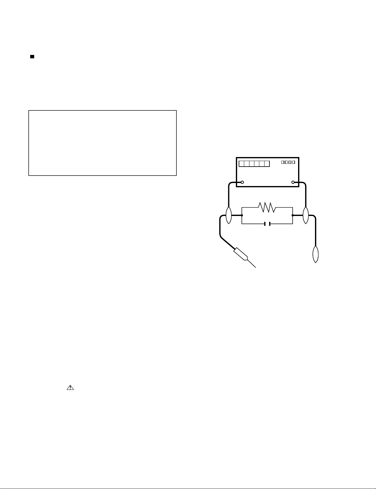
5. To be sure that no shock hazard exists, check for leakage current in
the following manner.
• Plug the AC cord directly into a 220~240 volt AC outlet.
• Using two clip leads, connect a 1.5k ohm, 10 watt resistor paralleled by a 0.15µF capacitor in series with all exposed metal cabinet
parts and a known earth ground, such as electrical conduit or electrical ground connected to an earth ground.
///////////////////////////////////////////////////////////////////////////////////////////////////////////////////////////////////////////////////////////////////////////////////////////////////////////////////////////////////////////
TO EXPOSED
METAL PARTS
SAFETY NOTICE
Many electrical and mechanical parts in LCD color television have
special safety-related characteristics.
These characteristics are often not evident from visual inspection, nor
can protection afforded by them be necessarily increased by using
replacement components rated for higher voltage, wattage, etc.
Replacement parts which have these special safety characteristics are
identified in this manual; electrical components having such features
are identified by “ ” and shaded areas in the Replacement Parts
List and Schematic Diagrams.
///////////////////////////////////////////////////////////////////////////////////////////////////////////////////////////////////////////////////////////////////////////////////////////////////////////////////////////////////////////
For continued protection, replacement parts must be identical to those
used in the original circuit.
The use of a substitute replacement parts which do not have the same
safety characteristics as the factory recommended replacement parts
shown in this service manual, may create shock, fire or other hazards.
1.5k ohm
10W
0.15µF
TEST PROBE
CONNECT TO
KNOWN EARTH
GROUND
i
LC-32DH65E/S, LC-37DH65E/S
Precautions for using lead-free solder
Employing lead-free solder
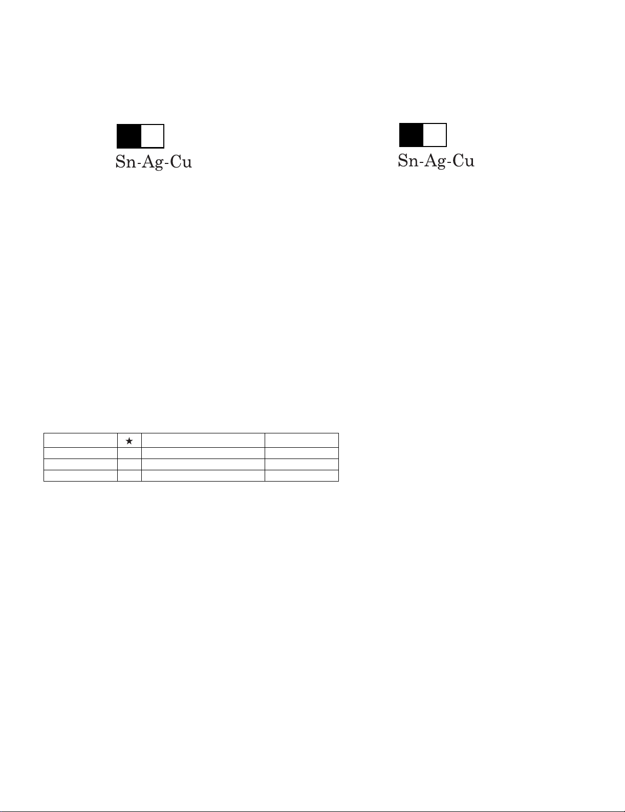
• “PWBs” of this model employs lead-free solder. The LF symbol indicates lead-free solder, and is attached on the PWBs and service manuals. The
alphabetical character following LF shows the type of lead-free solder.
Example:
L Fa
Indicates lead-free solder of tin, silver and copper.
Indicates lead-free solder of tin, silver and copper.
L F a/a
Using lead-free wire solder
• When fixing the PWB soldered with the lead-free solder, apply lead-free wire solder. Repairing with conventional lead wire solder may cause damage or accident due to cracks.
As the melting point of lead-free solder (Sn-Ag-Cu) is higher than the lead wire solder by 40 °C, we recommend you to use a dedicated soldering
bit, if you are not familiar with how to obtain lead-free wire solder or soldering bit, contact our service station or service branch in your area.
Soldering
• As the melting point of lead-free solder (Sn-Ag-Cu) is about 220 °C which is higher than the conventional lead solder by 40 °C, and as it has poor
solder wettability, you may be apt to keep the soldering bit in contact with the PWB for extended period of time. However, Since the land may be
peeled off or the maximum heat-resistance temperature of parts may be exceeded, remove the bit from the PWB as soon as you confirm the
steady soldering condition.
Lead-free solder contains more tin, and the end of the soldering bit may be easily corroded. Make sure to turn on and off the power of the bit as
required.
If a different type of solder stays on the tip of the soldering bit, it is alloyed with lead-free solder. Clean the bit after every use of it.
When the tip of the soldering bit is blackened during use, file it with steel wool or fine sandpaper.
• Be careful when replacing parts with polarity indication on the PWB silk.
Lead-free wire solder for servicing
Part No. Description Code
ZHNDAi123250E J φ0.3mm 250g (1roll) BL
ZHNDAi126500E J φ0.6mm 500g (1roll) BK
ZHNDAi12801KE J φ1.0mm 1kg (1roll) BM
ii
LC-32DH65E/S, LC-37DH65E/S
End of life disposal
End of life disposal
A. Information on Disposal for Users (private households)
1. In the European Union
Attention: If you want to dispose of this equipment, please do not use the ordinary dust bin!
Used electrical and electronic equipment must be treated separately and in accordance with legislation that requires
proper treatment, recovery and recycling of used electrical and electronic equipment.
Following the implementation by member states, private households within the EU states may return their used
Attention: Your product
is marked with this
symbol. It means that
used electrical and
electronic products
should not be mixed
with general household
waste. There is a
separate collection
system for these
products.
electrical and electronic equipment to designated collection facilities free of charge*. In some countries* your local
retailer may also take back your old product free of charge if you purchase a similar new one.
*) Please contact your local authority for further details.
If your used electrical or electronic equipment has batteries or accumulators, please dispose of these separately
beforehand according to local requirements.
By disposing of this product correctly you will help ensure that the waste undergoes the necessary treatment, recovery
and recycling and thus prevent potential negative effects on the environment and human health which could otherwise
arise due to inappropriate waste handling.
2. In other Countries outside the EU
If you wish to discard this product, please contact your local authorities and ask for the correct method of disposal.
For Switzerland: Used electrical or electronic equipment can be returned free of charge to the dealer, even if you don’t
purchase a new product. Further collection facilities are listed on the homepage of www.swico.ch or www.sens.ch.
B. Information on Disposal for Business Users
1. In the European Union
If the product is used for business purposes and you want to discard it:
Please contact your SHARP dealer who will inform you about the take-back of the product. You might be charged for
the costs arising from take-back and recycling. Small products (and small amounts) might be taken back by your local
collection facilities.
For Spain: Please contact the established collection system or your local authority for take-back of your used
products.
2. In other Countries outside the EU
If you wish to discard of this product, please contact your local authorities and ask for the correct method of disposal.
Information on Battery Disposal
For EU: The crossed-out wheeled bin implies that used batteries should not be put to the general household waste!
There is a separate collection system for used batteries, to allow proper treatment and recycling in accordance with
legislation. Please contact your local authority for details on the collection and recycling schemes.
For Switzerland: The used battery is to be returned to the selling point.
For other non-EU countries: Please contact your local authority for correct method of disposal of the used battery.
iii
LC32DH65E
CHAPTER 1. OPERATION MANUAL
[1] SPECIFICATIONS
LC-32DH65E/S, LC-37DH65E/S
Service Manual
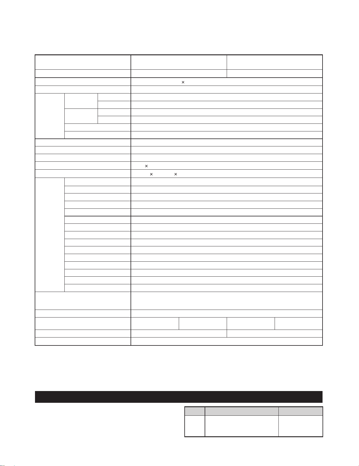
Item
LCD panel
Resolution
Video Colour System PAL/SECAM/NTSC 3.58/NTSC 4.43/PAL 60
TV Function TV-Standard Analogue CCIR (B/G, I, D/K, L/L’)
Digital DVB-T (2K/8K OFDM)
Receiving
Channel
TV-Tuning System Auto Preset 999 ch: non-Nordic / 9999 ch: Nordic (ATV: 99 ch), Auto Label, Auto Sort
STEREO/BILINGUAL NICAM/A2
Brightness 450 cd/m
Backlight life 60,000 hours (when “Backlight” is set to the default position)
Viewing angles H: 176°, V: 176°
Audio amplifier
Speaker
Terminals Antenna
RS-232C D-Sub 9 pin male connector
EXT1 SCART (AV input, Y/C input, RGB input, TV output)
EXT2 SCART (AV input/monitor output, Y/C input, AV Link, RGB input)
EXT3 COMPONENT IN: Y/P
EXT4 15 pin mini D-sub, Ø 3.5 mm jack*
HDMI1 (EXT5) HDMI
HDMI2 (EXT6) HDMI, Ø 3.5 mm jack*
HDMI3 (EXT7) HDMI
EXT8 RCA pin (AV input)
USB USB 2.0
DIGITAL AUDIO OUTPUT Optical S/PDIF Digital audio output
C. I. (Common Interface) EN50221, R206001
OUTPUT RCA pin (AUDIO R/L)
Headphones Ø 3.5 mm jack (Audio output)
OSD language
Power Requirement AC 220–240 V, 50 Hz
Power Consumption
(Method IEC62087)
Weight 11.5 kg (Without stand), 13.5 kg (With stand)
Operating temperature
The HDMI2 and EXT4 terminals can both use the same audio input terminal.
*
As a part of our policy of continuous improvement, SHARP reserves the right to make design and specification changes for product
•
improvement without prior notice. The performance specification figures indicated are nominal values of production units. There may be some
deviations from these values in individual units.
VHF/UHF E2–E69 ch, F2–F10 ch, I21–I69 ch, IR A–IR J ch (Digital: IR A ch–E69 ch)
CATV Hyper-band, S1–S41 ch
32" LCD COLOUR TV,
Model: LC-32DH65E, LC-32DH65S
32" Advanced Super View & BLACK TFT LCD 37" Advanced Super View & BLACK TFT LCD
2,073,600 pixels (1,920 1,080)
2
10 W 2
(40 mm 110 mm) 2
UHF/VHF 75
Czech, Danish, Dutch, English, Estonian, Finnish, French, German, Greek, Hungarian, Italian,
Latvian, Lithuanian, Norwegian, Polish, Portuguese, Russian, Slovak, Slovene, Spanish,
Swedish, Turkish, Ukrainian
LC-32DH65E
LC-32DH65S
0°Cto+40°C
Ω Din type (Analogue & Digital)
B(CB)/PR(CR), RCA pin (AUDIO R/L)
142 W (0.5 W Standby)
37" LCD COLOUR TV,
Model: LC-37DH65E, LC-37DH65S
LC-37DH65E
LC-37DH65S
14.5 kg (Without stand), 16.5 kg (With stand)
172 W (0.5 W Standby)
NOTE
Refer to the inside back cover for dimensional drawings.
•
Optional accessory
The listed optional accessories are available for this LCD
colour TV. Please purchase them at your nearest shop.
Additional optional accessories may be available in the near
•
future. When purchasing, please read the newest catalogue for
compatibility and check the availability.
1 – 1
No. Part name Part number
Wall mount bracket
(LC-32DH65E, LC-32DH65S,
1
AN-37AG5
LC-37DH65E, LC-37DH65S)
LC-32DH65E/S, LC-37DH65E/S
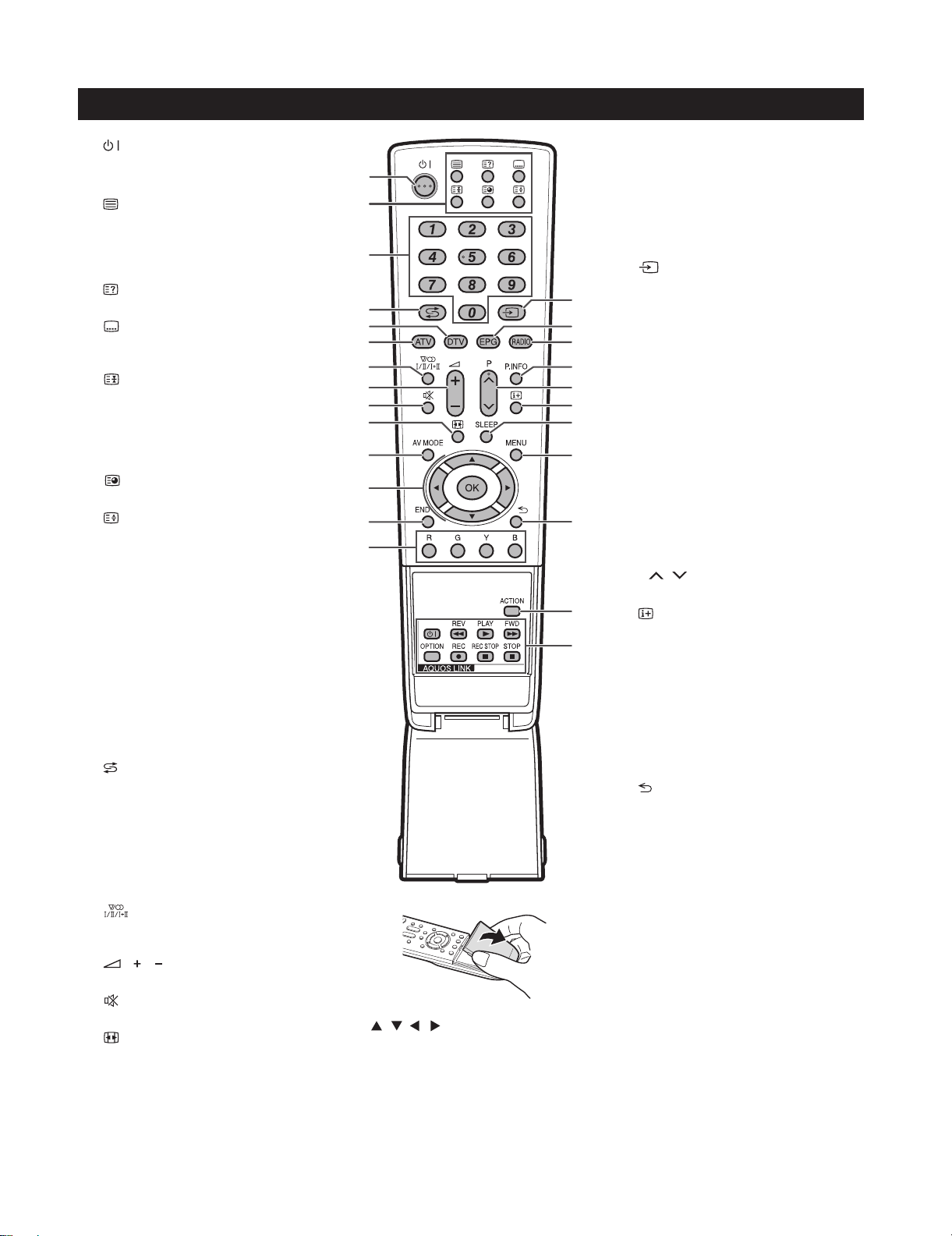
[2] OPERATION MANUAL
Remote control unit
1
2
3
4
5
6
7
8
9
10
11
(Standby/On)
Buttons for useful operations
(Teletext)
ATV: Display analogue teletext
DTV: Select MHEG-5 and teletext for
DTV.
(Reveal hidden Teletext)
(Subtitle)
Switch subtitle languages on/off.
(Freeze/Hold)
Press to freeze a moving image on
the screen.
Teletext: Stop updating teletext
pages automatically or release the
hold mode.
(Subpage)
(Top/Bottom/Full)
Set the area of magnification in
teletext mode.
0–9 numeric buttons
Set the channel.
Enter desired numbers.
Set the page in teletext mode.
•
When the five Nordic countries
(Sweden, Norway, Finland,
Denmark, or Iceland) are selected
in the country setting from “Auto
Installation”, DTVservices are
four digits. When another country
is selected, DTV services are
three digits.
(Flashback)
Press to return to the previously
selected channel or external input.
DTV
Press to access digital TV mode.
ATV
Press to access conventional
analogue TV mode.
(Sound mode)
Select a sound multiplex mode
/ (Volume)
Increase/decrease TV volume.
(Mute)
TV sound on/off.
(WIDE MODE)
Select a wide mode.
AV MODE
Select a video setting.
1
2
3
4
5
6
7
8
9
10
11
12
13
14
/ / / (Cursor)
12
Select a desired item on the setting
screen.
OK
Execute a command within the
“MENU” screen.
ATV/DTV: Display the programme
list when no other “MENU” screen is
running.
15
16
17
18
19
20
21
22
23
24
25
13
END
Exit the “MENU” screen.
14
R/G/Y/B (Colour) buttons
The coloured buttons are
correspondingly used to select the
coloured items on the screen (e.g.
EPG, MHEG-5, Teletext).
15
16
17
18
19
20
21
22
23
24
25
(INPUT SOURCE)
Select an input source.
EPG
DTV: Display the EPG screen.
RADIO
DTV: Switch between Radio and
Data mode.
•
When only data broadcasting (no
radio broadcasting) is transmitted
by DVB, the radio broadcasting
will be skipped.
P. INFO
Press to display programme
information which is transmitted
through digital video broadcasting in
the upper left corner of the screen
(DTV only).
P/
Select the TV channel.
(Display information)
Press to display the station
information (channel number, signal,
etc.) in the upper right corner of the
screen.
SLEEP
Press to schedule a time for the TV
to automatically standby.
MENU
“MENU” screen on/off.
(Return)
Return to the previous “MENU”
screen.
ACTION (Action Mode)
This key does not work on this
model.
AQUOS LINK buttons
If external equipment such as a
AQUOS BD Player is connected via
HDMI cables and is AQUOS LINK
compatible, you can use these
AQUOS LINK buttons.
1 – 2
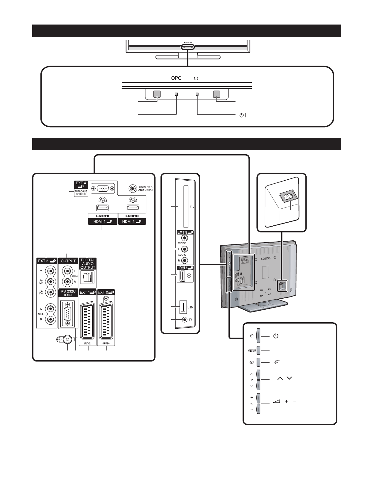
TV (Front view)
LC-32DH65E/S, LC-37DH65E/S
Remote control sensor
TV (Rear view)
1
4 56
OPC indicator
2
OPC sensor
(Standby/On) indicator
11
16
3
12
13
14
15
7 8 9 10
WARNING:
Excessive sound pressure from earphones and headphones can cause hearing loss.
EXT4 (ANALOGUE RGB/AUDIO)
1
terminals*
HDMI1 (HDMI) terminal
2
HDMI2 (HDMI/AUDIO) terminals*
3
EXT3 (COMPONENT/AUDIO)
4
terminals
OUTPUT (AUDIO) terminals
5
DIGITAL AUDIO OUTPUT terminal
6
Antenna terminal
7
RS-232C terminal
8
EXT1 (RGB) terminal
9
EXT2 (RGB) terminal
10
COMMON INTERFACE slot
11
EXT8 terminals
12
HDMI3 (HDMI) terminal
13
USB terminal
14
Headphones
15
AC INPUT terminal
16
1 – 3
(Power) button
MENU button
(INPUT SOURCE)
button
P
/
Programme (channel)
buttons
/
Vo l u m e
buttons
The HDMI2 and EXT4 terminals
*
can both use the same audio input
terminal. However, the proper item
must be selected in the “PC Audio
Select” menu.
LC-32DH65E/S, LC-37DH65E/S
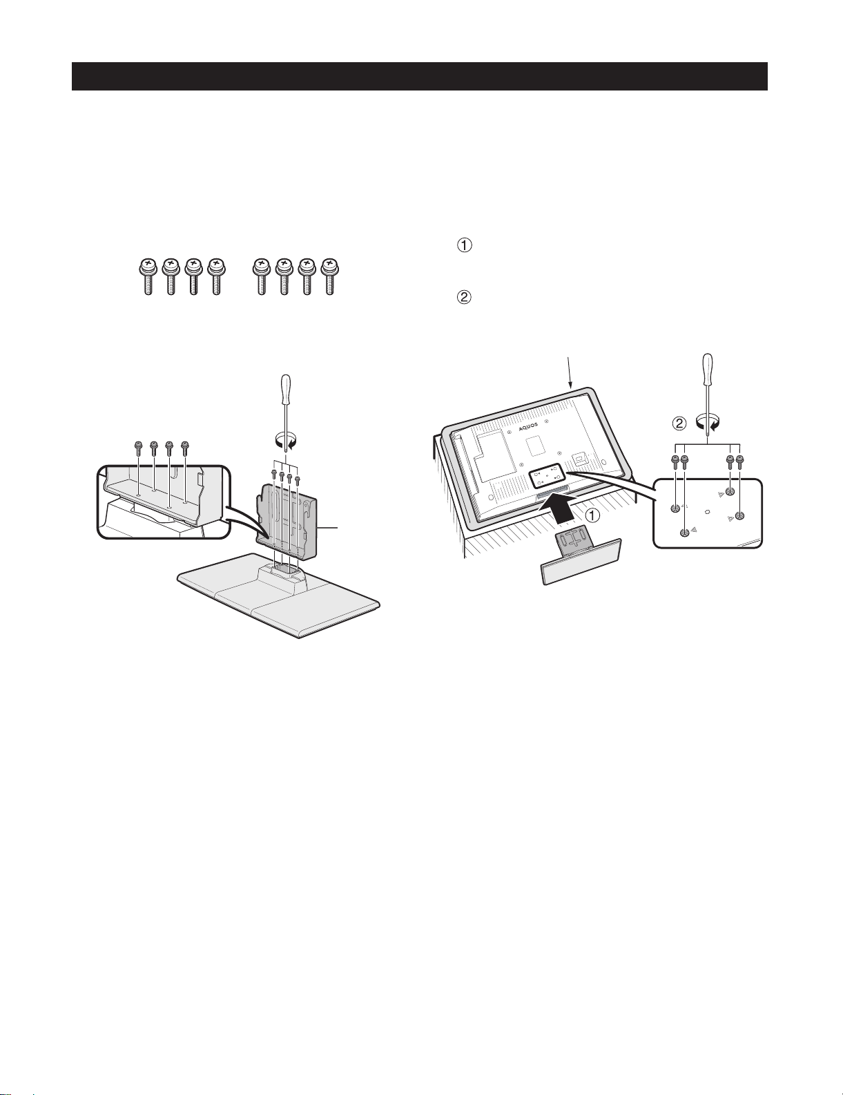
Attaching the stand unit
Before attaching (or detaching) the stand, unplug the AC cord from the AC INPUT terminal.
•
Before performing work, spread cushioning over the surface on which you will be laying the TV. This will prevent
•
it from being damaged.
CAUTION
Attach the stand in the correct direction.
•
Be sure to follow the instructions. Incorrect installation of the stand may result in the TV falling over.
•
Confirm that there are eight screws with the
1
stand unit.
Attach the supporting post for the stand unit
2
onto the base using the four screws with the
screw driver (supplied) as shown.
Supporting
post
Inserting the stand.
3
Insert the stand into the openings on the
bottom of the TV (Hold the stand so it will
not drop from the edge of the base area).
Insert and tighten the four screws into the
four holes on the rear of the TV.
Soft cushion
NOTE
To detach the stand unit, perform the steps in reverse
•
order.
1 – 4
LC-32DH65E/S, LC-37DH65E/S
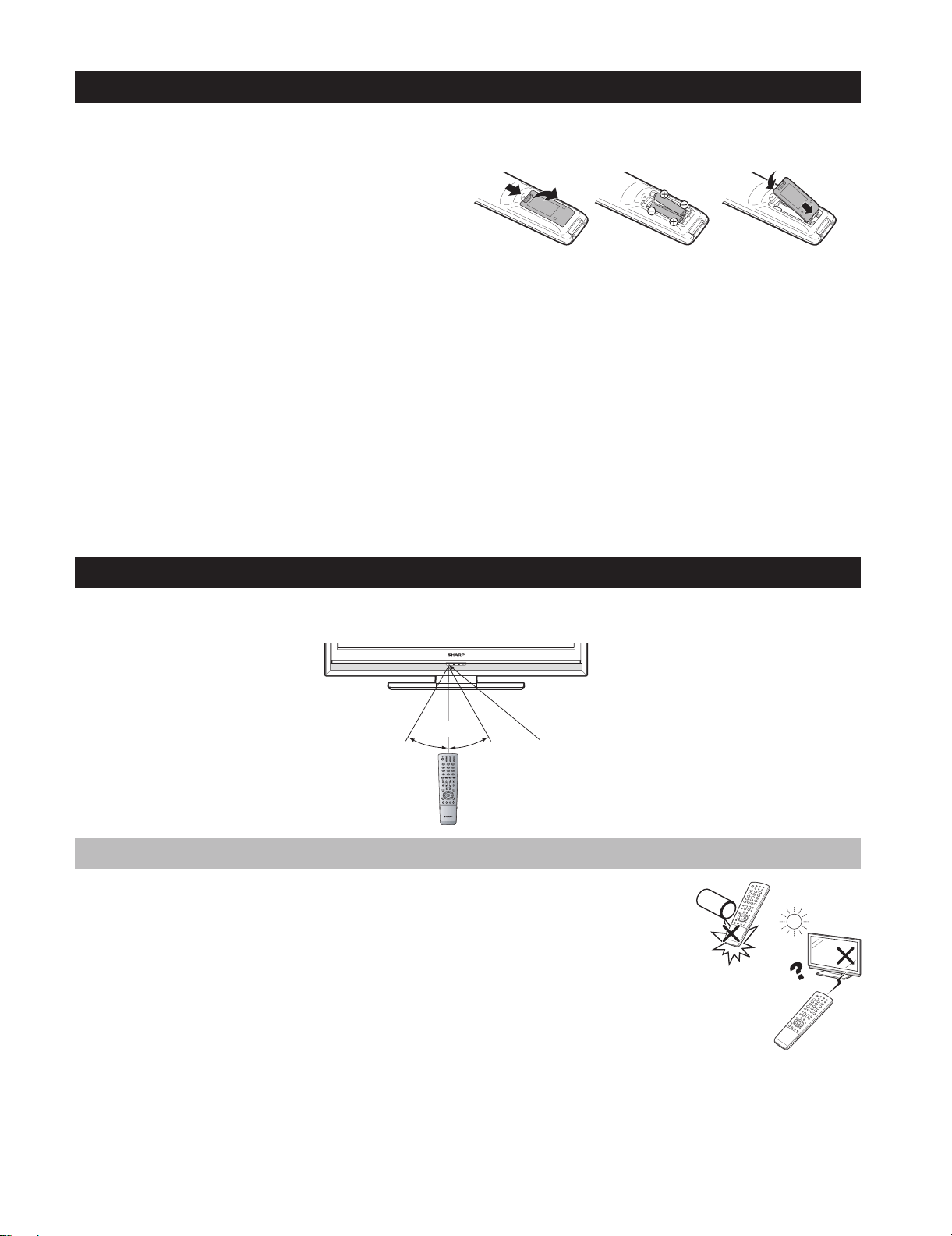
Inserting the batteries
Before using the TV for the first time, insert two supplied “AAA” size alkaline batteries. When the batteries become
depleted and the remote control unit fails to operate, replace the batteries with new “AAA” size batteries.
Open the battery cover.
1
2
Insert two supplied “AAA” size alkaline batteries.
Place batteries with their terminals corresponding to the
•
(+) and (-) indications in the battery compartment.
Close the battery cover.
3
CAUTION
Improper use of batteries can result in chemical leakage or explosion. Be sure to follow the instructions below.
Do not mix batteries of different types. Different types of batteries have different characteristics.
•
Do not mix old and new batteries. Mixing old and new batteries can shorten the life of new batteries or cause
•
chemical leakage in old batteries.
Remove batteries as soon as they have worn out. Chemicals that leak from batteries can cause a rash. If you
•
find any chemical leakage, wipe thoroughly with a cloth.
The batteries supplied with this product may have a shorter life expectancy due to storage conditions.
•
If you will not be using the remote control unit for an extended period of time, remove the batteries from it.
•
When replacing the batteries, use alkaline batteries instead of zinc-carbon ones.
•
Note on disposing batteries:
The batteries provided contain no harmful materials such as cadmium, lead or mercury.
Regulations concerning used batteries stipulate that batteries may no longer be thrown out with the household
rubbish. Deposit any used batteries free of charge into the designated collection containers set up at commercial
businesses.
Using the remote control unit
Use the remote control unit by pointing it towards the remote control sensor. Objects between the remote control
unit and sensor may prevent proper operation.
5m
30° 30°
Remote control sensor
Cautions regarding the remote control unit
•
Do not expose the remote control unit to shock. In addition, do not expose the
remote control unit to liquids, and do not place in an area with high humidity.
•
Do not install or place the remote control unit under direct sunlight. The heat
may cause deformation of the unit.
•
The remote control unit may not work properly if the remote control sensor of
the TV is under direct sunlight or strong lighting. In such cases, change the
angle of the lighting or the TV, or operate the remote control unit closer to the
remote control sensor.
1 – 5
LC-32DH65E/S, LC-37DH65E/S
Troubleshooting
Problem Possible Solution
No power.•
The TV cannot be operated.•
Remote control unit does not operate.•
Picture is cut off.• Is the image position correct?
Strange colour, light colour, or dark
• Adjust the picture tone.
colour, or colour misalignment.
Power is suddenly turned off.• The TV’s internal temperature has increased.
No picture.• Are connections to external equipment correct?
No sound.• Is the volume too low?
The TV sometimes makes a cracking
• This is not a malfunction. This happens when the cabinet slightly expands and contracts
sound.
Check if you pressed B on the remote control unit.
•
If the indicator on the TV lights up red, press B.
Is the AC cord disconnected?
•
Check if you pressed a on the TV.
•
•
External influences such as lightning, static electricity, etc., may cause improper operation. In this
case, operate the TV after first turning off the power, or unplugging the AC cord and re-plugging
it in after one or two minutes.
Are batteries inserted with polarity (+, -) aligned?
•
Are batteries worn out? (Replace with new batteries.)
•
Are you using it under strong or fluorescent lighting?
•
Is a fluorescent light illuminating to the remote control sensor?
•
•
Are screen mode adjustments (WIDE MODE) such as picture size made correctly?
•
•
Is the room too bright? The picture may look dark in a room that is too bright.
•
Check the “Colour System” setting.
•
•
Remove any objects blocking the vent or clean.
Is the “Sleep Timer” set? Select “Off” from the “Sleep Timer” menu.
•
Is “No Signal Off” or “No Operation Off” activated?
•
•
Is the input signal type selected correctly after connection?
•
Is the correct input source selected?
•
Is a non-compatible signal being input?
•
Is the picture adjustment correct?
•
Is the antenna connected properly?
•
Is “On” selected in “Audio Only”?
•
•
Make sure that headphones are not connected.
•
Check if you pressed e on the remote control unit.
•
Is the proper item selected in the “PC Audio Select” menu when connecting devices to the
•
HDMI2 terminal or the EXT4 terminal?
•
according to changes in temperature. This does not affect the TV’s performance.
Cautions regarding use in high and low temperature environments
•
When the TV is used in a low temperature space (e.g. room, office), the picture may leave trails or appear slightly delayed.
This is not a malfunction, and the TV will recover when the temperature returns to normal.
Do not leave the TV in a hot or cold location. Also, do not leave the TV in a location exposed to direct sunlight or near a
•
heater, as this may cause the cabinet to deform and the LCD panel to malfunction.
Storagetemperature:+5°Cto+35°C.
Information on the software license for this product
Software composition
The software included in this product is comprised of various software components whose individual copyrights are held by
SHARP or by third parties.
Software developed by SHARP and open source software
The copyrights for the software components and various relevant documents included with this product that were developed
or written by SHARP are owned by SHARP and are protected by the Copyright Act, international treaties, and other relevant
laws. This product also makes use of freely distributed software and software components whose copyrights are held by
third parties. These include software components covered by a GNU General Public License (hereafter GPL), a GNU Lesser
General Public License (hereafter LGPL) or other license agreement.
Obtaining source code
Some of the open source software licensors require the distributor to provide the source code with the executable software
components. GPL and LGPL include similar requirements. For information on obtaining the source code for the open source
software and for obtaining the GPL, LGPL, and other license agreement information, visit the following website:
http://www.sharp-eu.com/gpl/
We are unable to answer any questions about the source code for the open source software. The source code for the
software components whose copyrights are held by SHARP is not distributed.
Acknowledgements
The following open source software components are included in this product:
• linux kernel • busy box • uClibc • zlib • libpng • libjpeg
1 – 6
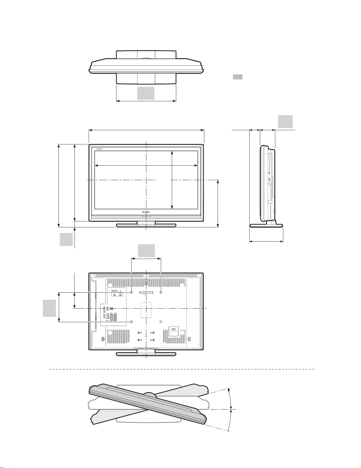
[3] DIMENSIONS
LC-32DH65E/S, LC-37DH65E/S
Unit: mm
( ) : LC-32DH65E/32DH65S
[ ] : LC-37DH65E/37DH65S
: LC-32DH65E/32DH65S
LC-37DH65E/37DH65S
400.0
400,0
(561.0) / [627.0]
(561,0) / [627,0]
(519.0) / [585.0]
(519,0) / [585,0]
42.0
(110.0)
(110.0)
(100.0)
(100.0)
(774.0) / [902.0]
(774,0) / [902,0]
(699.2) / [824.4]
(699,2) / [824,4]
200.0
200,0
(393.8) / [463.8]
(393,8) / [463,8]
(320.9) / [355.9]
(320,9) / [355,9]
(73.2)
(73,2)
[84.7]
[84,7]
(224.0) / [247.0]
(224,0) / [247,0]
96.8
96,8
200.0
200,0
15°
: LC-32DH65E/32DH65S
: LC-37DH65E/37DH65S
15°
1 – 7
LC-32DH65E/S, LC-37DH65E/S
LC32DH65E
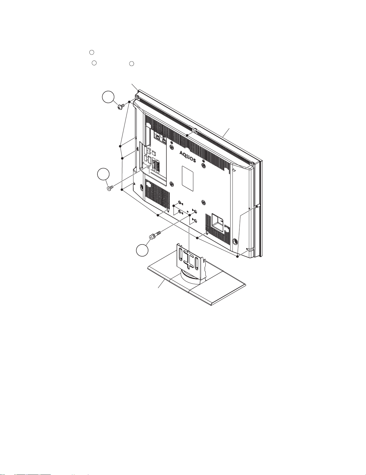
CHAPTER 2. REMOVING OF MAJOR PARTS
Service Manual
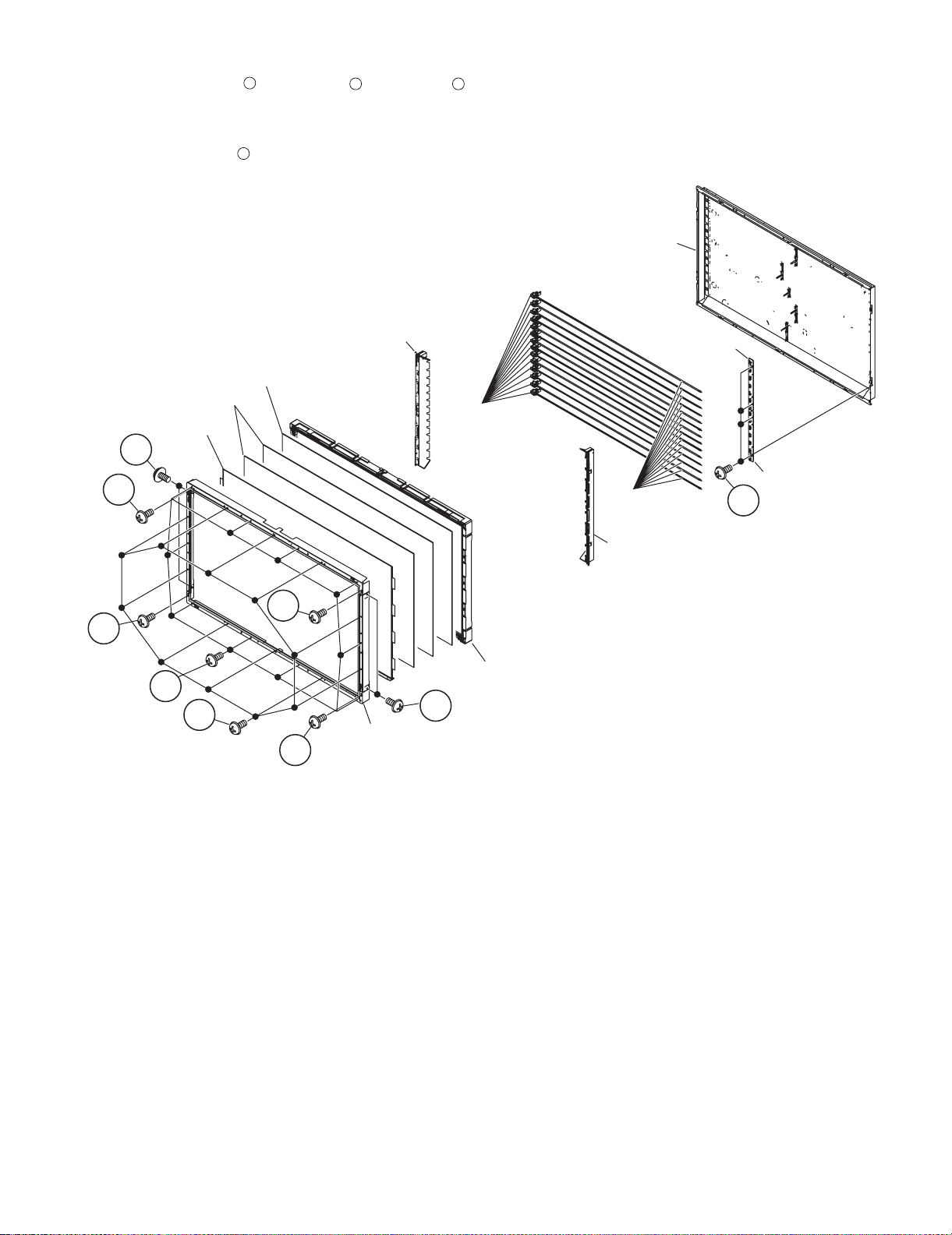
[1] REMOVING OF MAJOR PARTS (LC-32DH65E, LC-32DH65S)
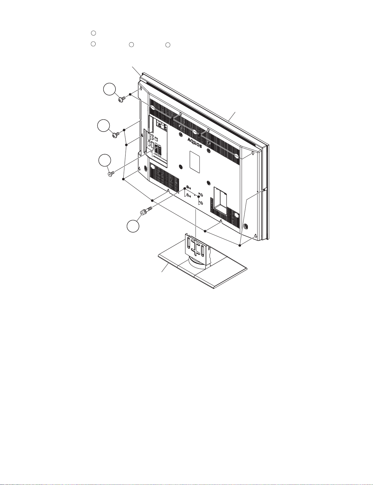
1. Remove the 4 lock screws and detach the Stand Unit.
2. Remove the 10 lock screws , 1 lock screws and detach the Rear Cabinet.
1
2
3
Rear Cabinet
2
3
Front Cabinet
1
Stand Unit
2 – 1
LC-32DH65E/S, LC-37DH65E/S
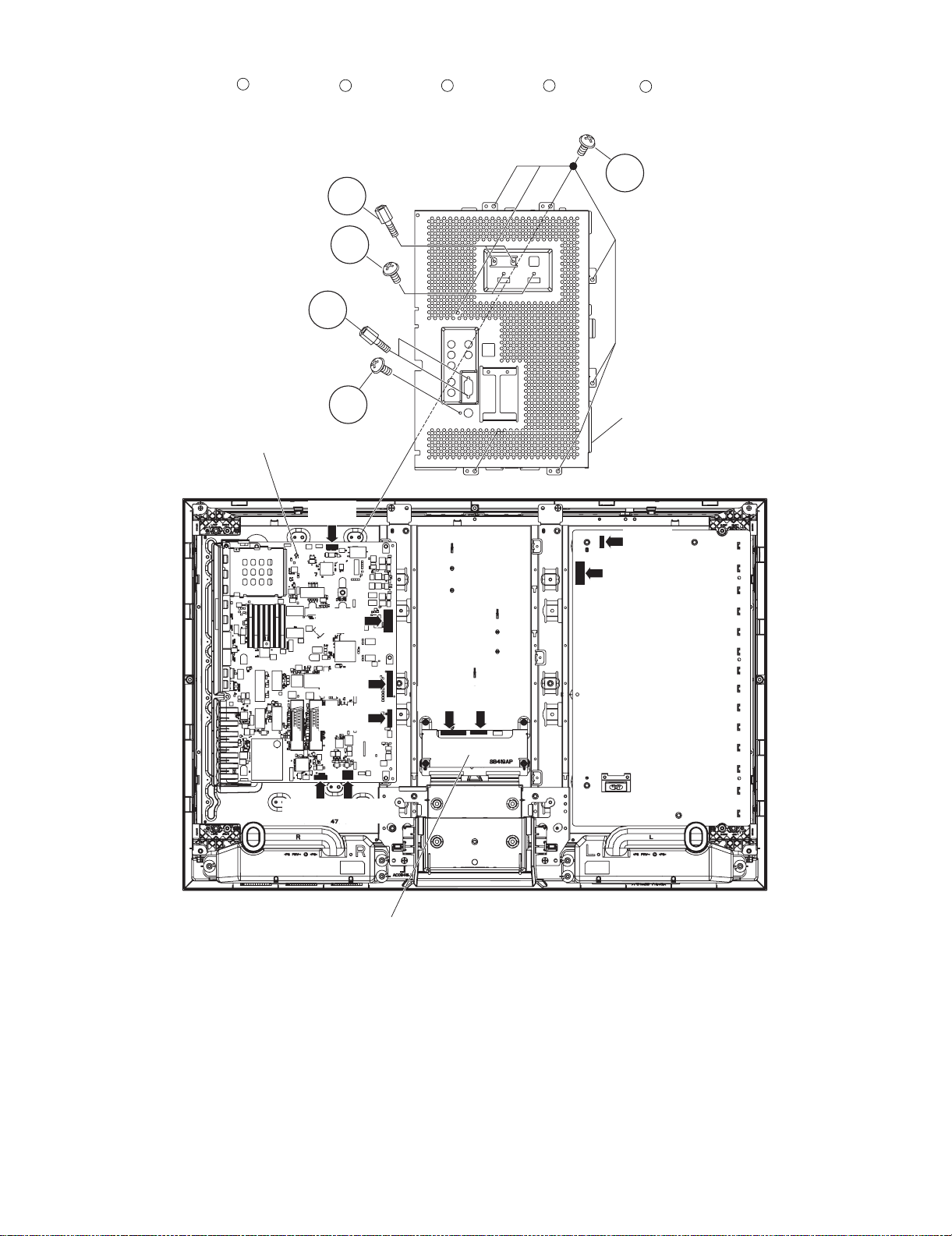
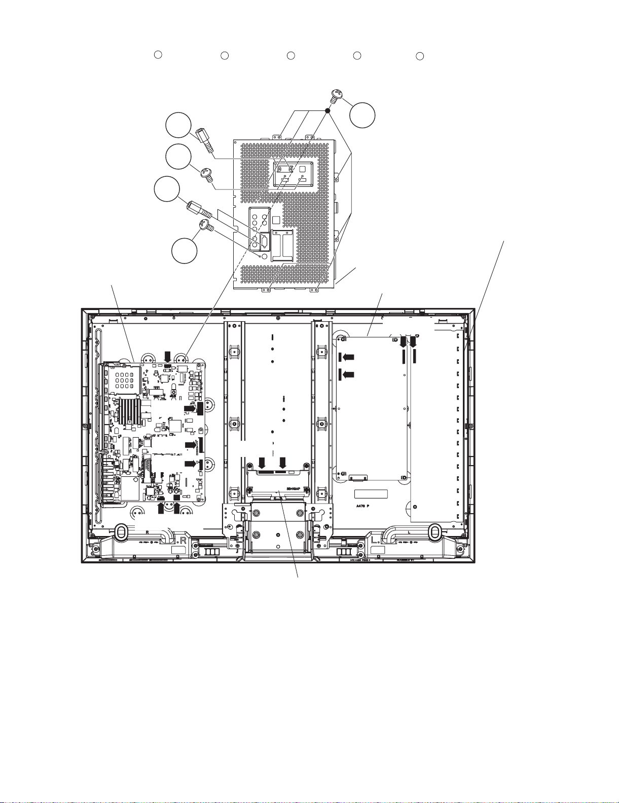
3. Remove the 7 lock screws , 2 lock screws , 2 lock screws , 2 lock screws , 1 lock screw and detach the Full Shield.
4. Disconnect all the connectors from all the PWBs.
1
2 3 4
5
1
2
3
4
5
Full Shield
MAIN Unit
[LB]
[PD]
[LW]
[LP]
[LP]
[SP][RA]
LCD Control Unit
[LW]
[LB]
[PD]
POWER/
INVERTER
Unit
2 – 2
LC-32DH65E/S, LC-37DH65E/S
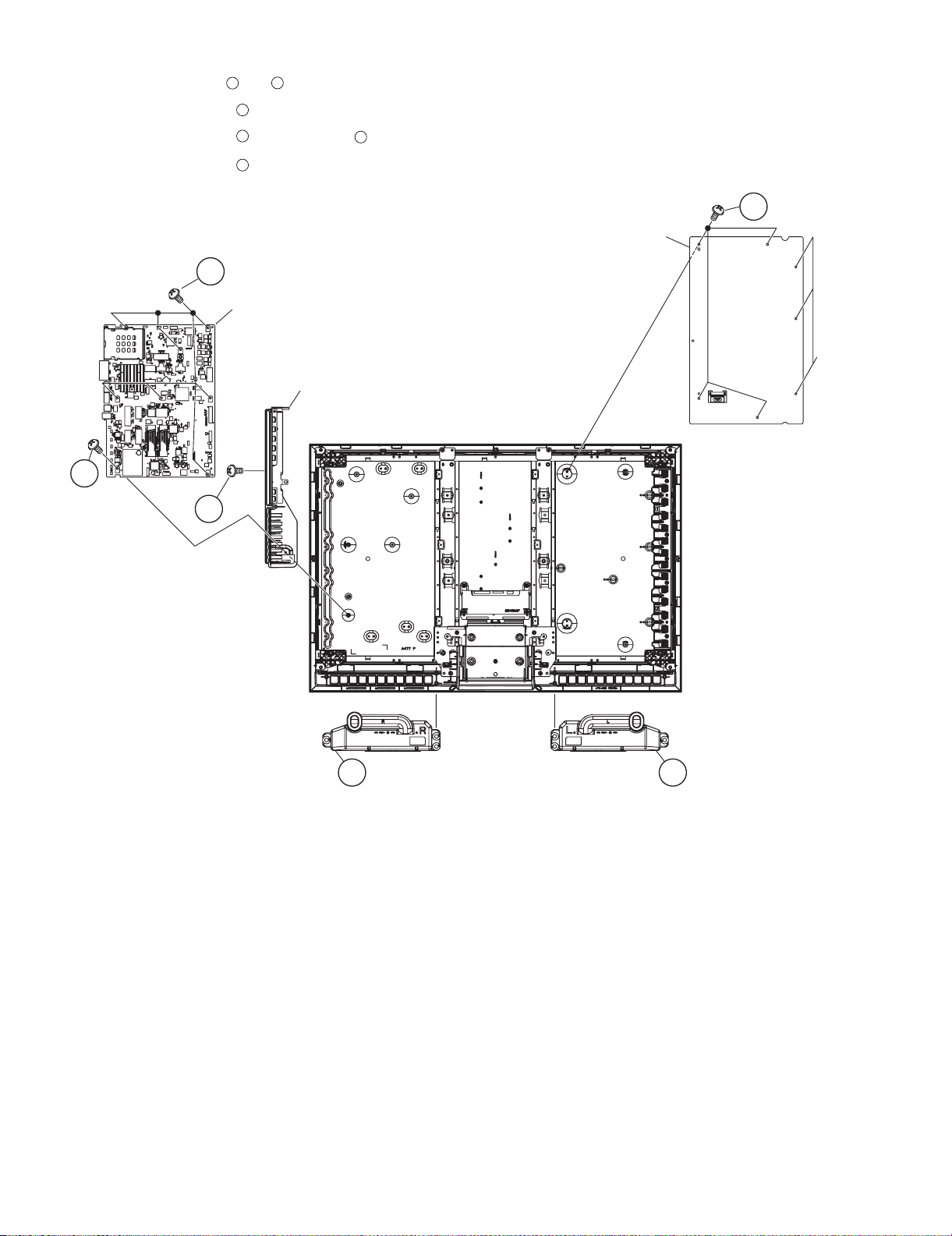
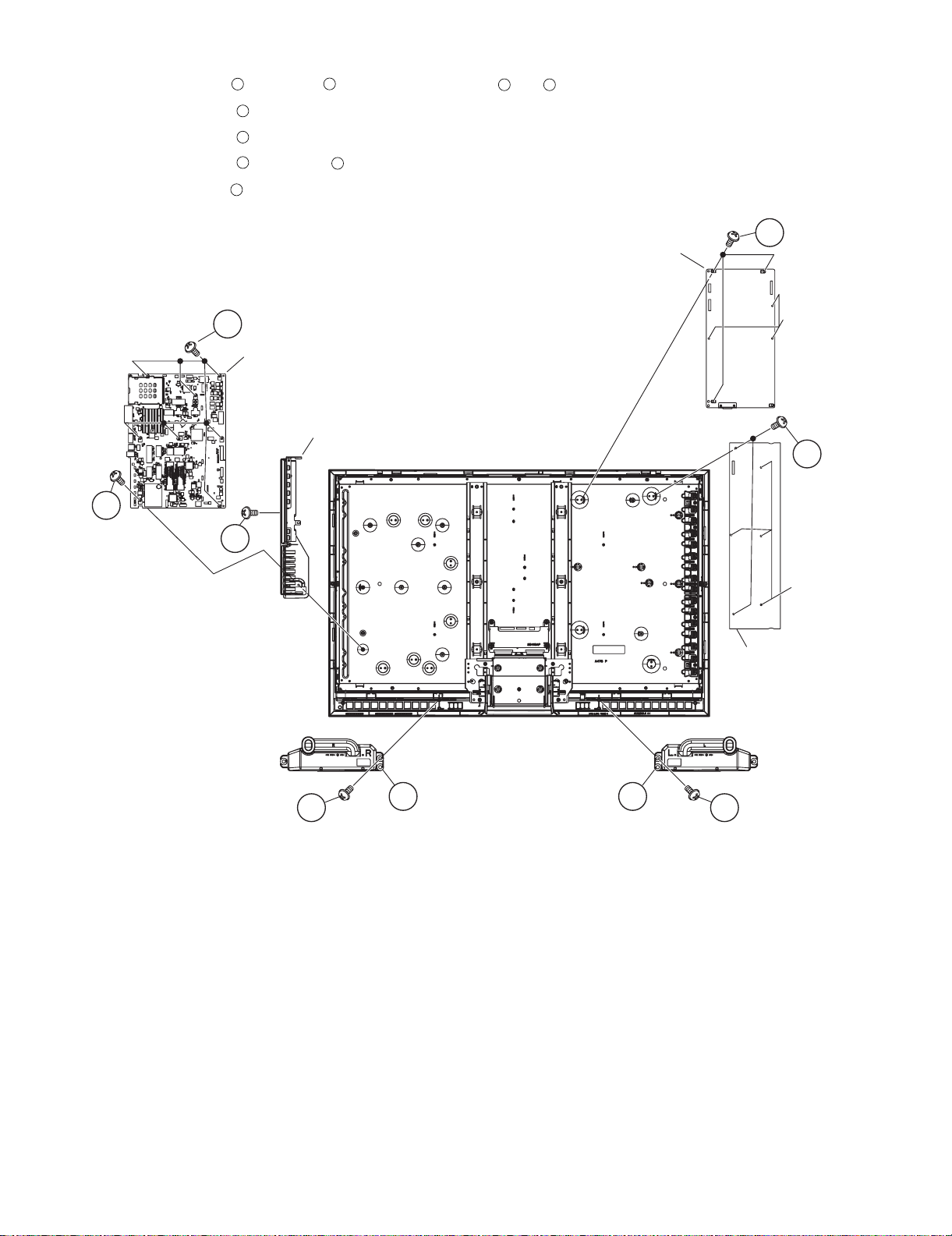
5. Remove the Speaker (L) , (R) .
6. Remove the 4 lock screws , the 3 hooks and detach the POWER/INVETER Unit.
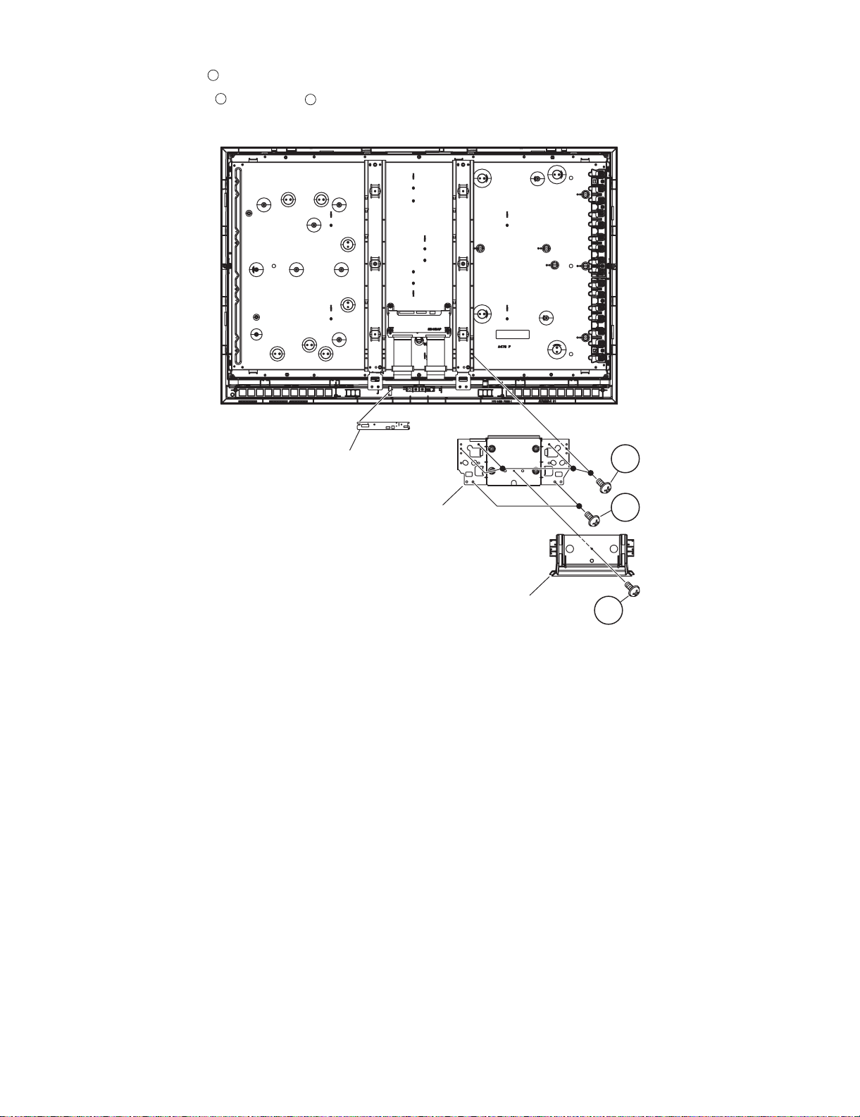
7. Remove the 7 lock screws , the 1 lock screw and detach the MAIN Unit.
8. Remove the 1 lock screws , and detach the Control Cover Ass’y from the MAIN Unit.
2
1
3
4
6
5
4
MAIN Unit
Control Cover Ass'y
5
6
POWER/
INVERTER
Unit
3
POWER
PWB
Holder
Speaker(R)
2 Speaker(L)1
2 – 3
LC-32DH65E/S, LC-37DH65E/S
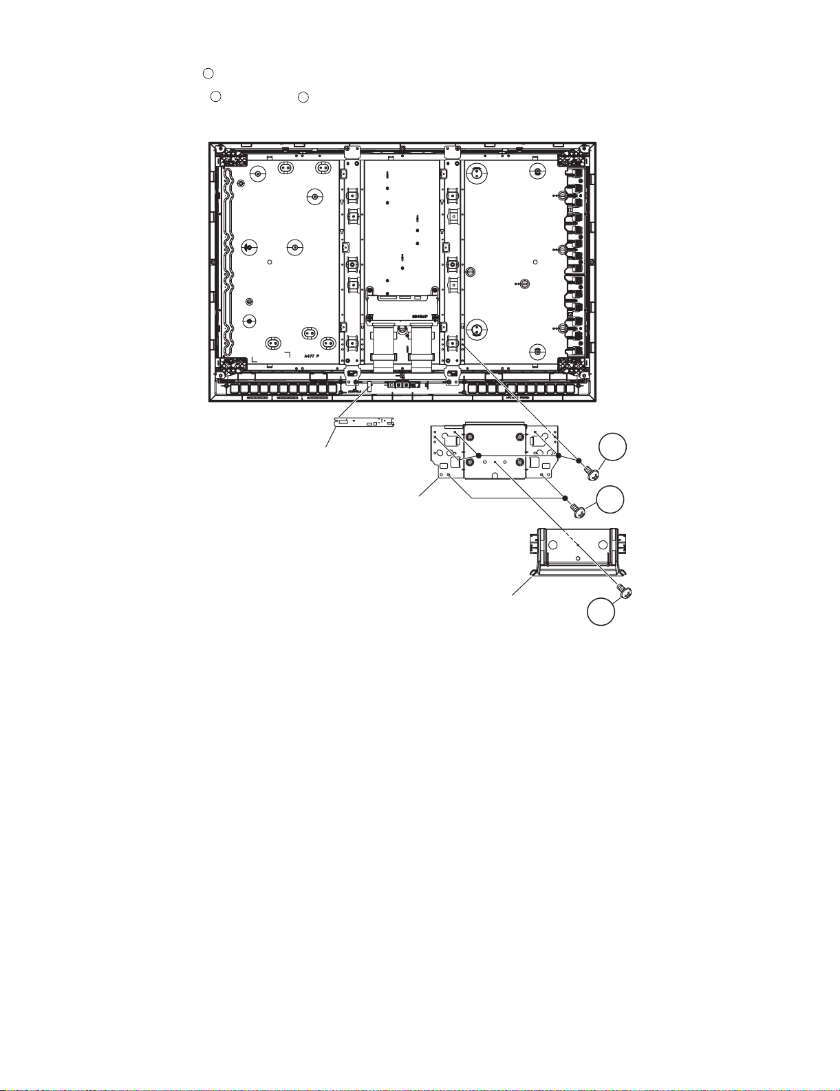
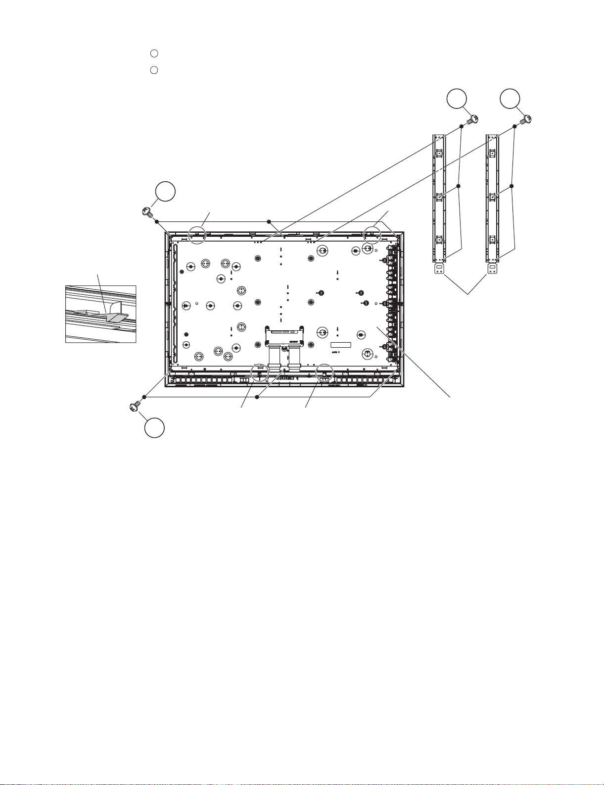
9. Remove the 1 lock screw and detach the Bottom Cover.
10.Remove the 2 lock screws 4 lock screws and detach the Stand Angle.
11.Remove the LED Unit.
1
2
3
LED Unit
3
Stand Angle
2
Bottom Cover
1
2 – 4
LC-32DH65E/S, LC-37DH65E/S
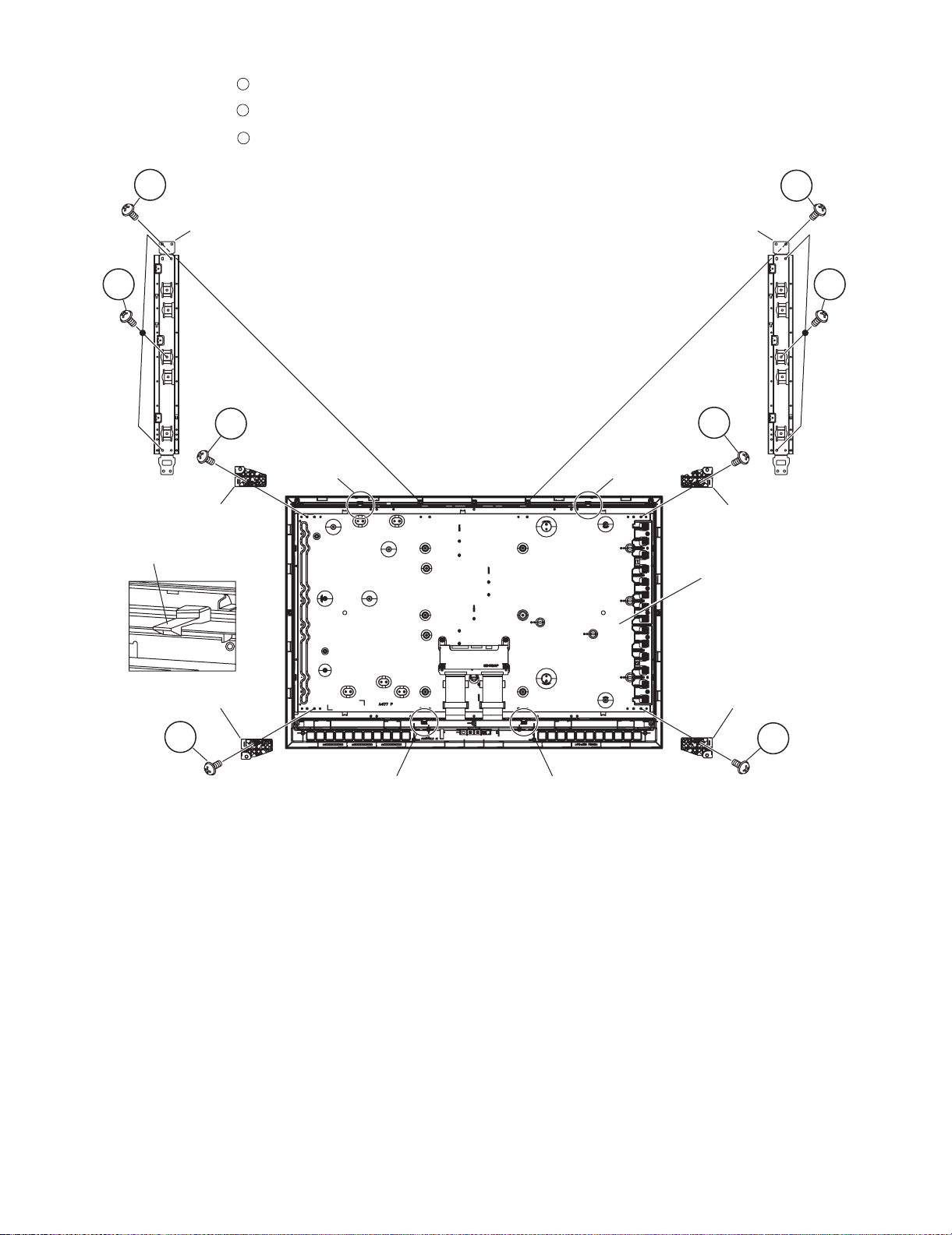
12.Remove the 2 lock screws , 4 hooks and detach the LCD Panel Module.
13.Remove the 4 lock screws , and detach the LCD Holder A, B.
14.Remove the 6 lock screws and detach the Panel Support Angle.
1
2
3
1
Panel Support Angle Panel Support Angle
3
2
Hook
LCD Holder B
1
3
2
Hook
LCD Holder A
Hook
LCD Panel
Module
LCD Holder BLCD Holder A
2
Hook
Hook
2
2 – 5
LC-32DH65E/S, LC-37DH65E/S
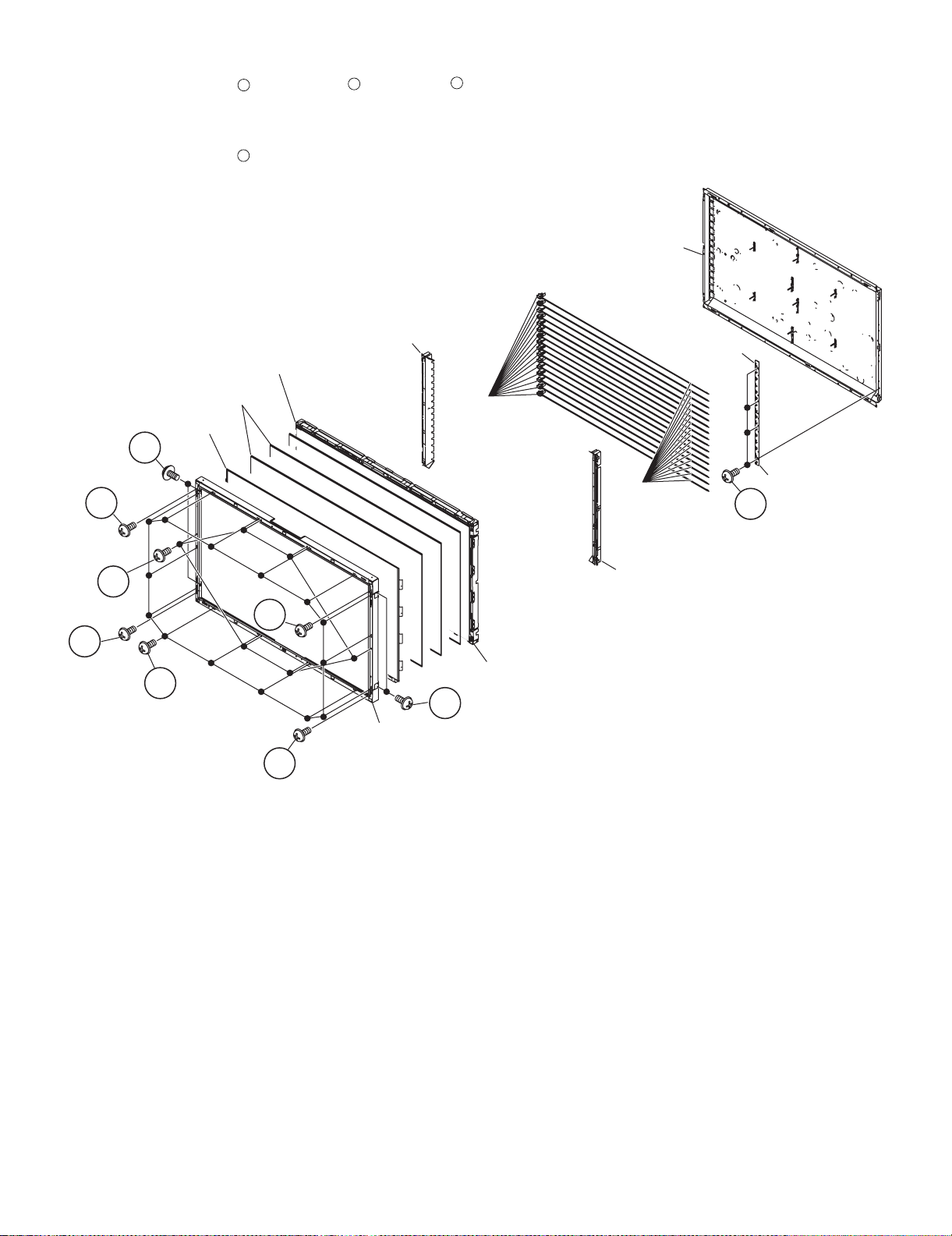
15.Remove the 10 lock screws 10 lock screws , 5 lock screws and Bezel Ass’y.
16.Detach the TFT LCD Panel, Lens Sheet and Diffusion Plate.
17.Detach the Panel Chassis Ass’y Lamp Holder (L), Lamp holder (R) and the Lamp Unit.
18.Remove the 4 lock screws and GND-PWBs
1
4
2 3
Back Light Chassis Ass'y
Lamp Holder(L)
Diffusion Plate
Lens Sheet
TFT LCD PANEL
Lamp Socket
3
3
GND-PWB
Lamp Unit
GND-PWB
4
Lamp Holder(R)
3
3
1
2
3
Bezel Ass'y
Panel Chassis Ass'y
3
2 – 6
LC-32DH65E/S, LC-37DH65E/S
[2] REMOVING OF MAJOR PARTS (LC-37DH65E, LC-37DH65S)
1. Remove the 4 lock screws and detach the Stand Unit.
2. Remove the 4 lock screws , 7 lock screws , 1 lock screw and detach the Rear Cabinet.
1
2
3
4
Rear Cabinet
2
Front Cabinet
3
4
1
Stand Unit
2 – 7
LC-32DH65E/S, LC-37DH65E/S
3. Remove the 7 lock screws , 2 lock screws , 2 lock screws , 2 lock screws , 1 lock screw and detach the Full Shield.
4. Disconnect all the connectors from all the PWBs.
1
2 3 4
5
1
2
3
4
INVERTER unit
5
Full Shield
MAIN unit
POWER unit
[BtoB]
[LB]
[LB]
[PD]
[LW]
[LP]
[SP][RA]
[LP]
[PD]
[LW]
LCD Control unit
2 – 8
LC-32DH65E/S, LC-37DH65E/S
3
5. Remove the 1 lock screw 1 lock screw and detach the Speaker (L) , (R) .
6. Remove the 2 lock screws , the 4 hooks and detach the INVETER Unit.
7. Remove the 3 lock screws , the 2 hooks and detach the POWER Unit.
8. Remove the 7 lock screws , 1 lock screw and detach the MAIN Unit.
9. Remove the 1 lock screw and detach the Control Cover Ass’y from the MAIN Unit.
1
5
6
7
9
2
8
4
7
MAIN Unit
Control Cover Ass'y
8
6
POWER Unit
POWER
PWB
Holder
5
9
POWER
PWB
Holder
INVERTER Unit
4
21
Speaker(R) Speaker(L)
3
2 – 9
LC-32DH65E/S, LC-37DH65E/S
10.Remove the 1 lock screw and detach the Bottom Cover.
11.Remove the 2 lock screws 4 lock screws and detach the Stand Angle.
12.Remove the LED Unit.
1
2
3
LED Unit
3
Stand Angle
Bottom Cover
2
1
2 – 10
LC-32DH65E/S, LC-37DH65E/S
13.Remove the 6 lock screws , and detach the Panel Support Angle.
14.Remove the 6 lock screws , 4 hooks and detach the LCD Panel Module.
1
2
2
Hook
Hook
Hook
1
1
Panel Support Angle
LCD Panel Module
Hook
Hook
2
2 – 11
LC-32DH65E/S, LC-37DH65E/S
15.Remove the 6 lock screws , 14 lock screws , 8 lock screws and detach the Bezel Ass’y.
16.Detach the TFT LCD Panel, Lens Sheet and Diffusion Pane.
17.Detach the Panel Chassis Ass’y, Lamp Holder (L), Lamp Holder (R) and the Lamp Unit.
18.Remove the 4 lock screws and detach GND-PWBs.
1
4
2
3
Back Light Chassis Ass'y
Lamp Holder(L)
Diffusion Plate
Lens Sheet
TFT LCD PANEL
Lamp Socket
3
3
Lamp Unit
GND-PWB1
GND-PWB2
4
1
Lamp Holder(R)
3
3
2
Panel Chassis Ass'y
3
Bezel Ass'y
3
2 – 12

LC-32DH65E/S, LC-37DH65E/S
LC32DH65E
CHAPTER 3. ADJUSTMENT PROCEDURE
Service Manual
[1] ADJUSTMENT PROCEDURE
1. Adjustment method after PWB and/or IC replacement due to repair
The unit is set to the optimum at the time of shipment from the factory. If any value should become improper or any adjustment is necessary due to
the part replacement, make an adjustment according to the following procedure.
1. Procure the following units in order to replace the main unit, IC8101, IC5001, or IC5003.
MAIN UNIT: DUNTKE685FM02 (LC-32DH65E/S)
DUNTKE685FM04 (LC-37DH65E/S)
NOTE: [Caution when replacing ICs in the main unit (IC1504)]
The above ICs are EEPROMs storing the EDID data of HDMI. Before replacing the relevant part, procure the following parts in which the data
have been rewritten.
IC1504 RH-IXC442WJN1S EDID (HDMI)
IC1503 RH-IXC697WJQZS EDID (PC)
2. After replacing the LCD panel or LCD control PWB, check PANEL_SIZE in the following procedure.
1) Enter the process adjustment mode.
2) Use the cursor keys / and P / of R/C to select the item [PANEL_SIZE] on the page 16/16.
3) Verify that the panel size is displayed.
4) If the size doesn't match, select the values of the panel size with the Vol / keys.
5) After selection in Step 4), press the OK key, and it is completed with OK displayed.
3. After replacing the LCD panel or LCD control PWB, adjust the VCOM in the following procedure.
1) Enter the process adjustment mode.
2) Use the cursor keys / and P / of R/C to select the item [VCOM ADJ] on the page 10/16.
3) Press the OK key to verify that the adjustment pattern is displayed.
4) Use the +/- keys of VOL of R/C to adjust the flicker in the center of the screen to minimum.
5) When the optimal state is achieved in Step 4, press the OK key to turn the pattern to OFF.
3 – 1
LC-32DH65E/S, LC-37DH65E/S
2. Entering and exiting the adjustment process mode
1. Unplug the AC power cord of running TV set to force off the power.
2. While holding down the “VOL (-)” and “INPUT” keys on the set at once, plug in the AC power cord to turn on the power.
The letter “K” appears on the screen.
3. Next, hold down the “VOL (-)” and “P ( )” keys on the set at once.
Multiple lines of blue characters appearing on the screen indicate that the set is now in the adjustment Process mode.
If you fail to enter the adjustment process mode (the display is the same as normal startup), retry the procedure.
4. To exit the adjustment process mode after the adjustment is done, unplug the AC power cord to force off the power. (When the power is turned off
with the remote controller, once unplug the AC power cord and plug it in again. In this case, wait 10 seconds or so before plugging.)
CAUTION:Use due care in handling the information described here lest the users should know how to enter the adjustment process mode. If the
settings are tampered with in this mode, unrecoverable system damage may result.
3. Remote controller key operation and description of display in adjustment process mode.
1. key operation
Remote controller key Main unit key Function
P ( / )
P ( / )
Moving an item (line) by one (UP/DOWN)
VOL (+/-) VOL (+/-) Changing a selected item setting (+1/-1)
Cursor ( / )
— Turning a page (PREVIOUS / NEXT)
Cursor (</>) — Changing a selected line setting (+10/-10)
INPUT INPUT Input source switching (toggle switching) (TV→EXT1~8)
RETURN — Returning to a present page.
OK — Executing a function.
Input mode is switched automatically when relevant adjustment is started so far as the necessary input signal is available.
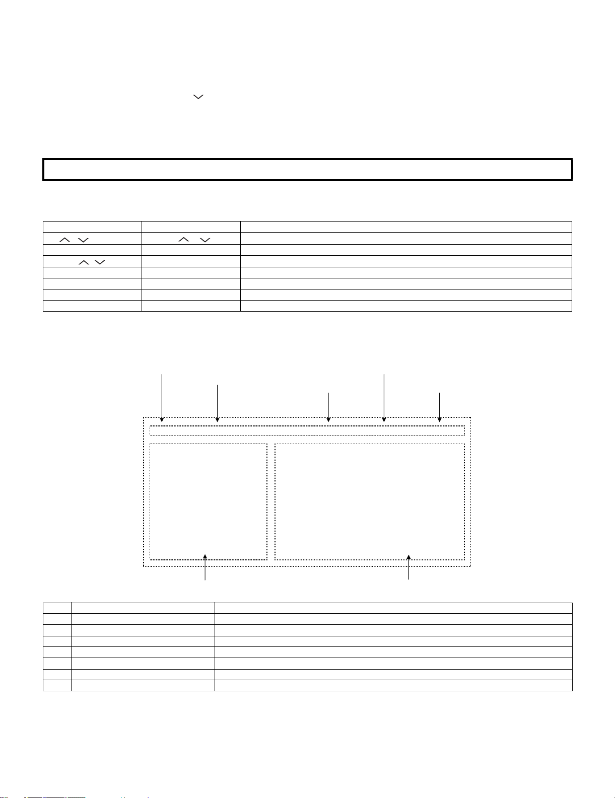
4. Description of display
(1) Page/ of present number of total pages (4) Inducing display
(2) Input that has been selected now
1/16 INPUT1 AUTO EURO 37E_DH65
MAIN Version
BOOT Version
Monitor Version
T-CON Version/H.264 Version
CPLD Version
EQ DATA CHECKSUM
LAMP ERROR
MONITOR ERR CAUSE
NORMAL STANDBY CAUSE
ERROR STANDBY CAUSE
(3) Present colour system
1.00 (E 2008/07/10 D)
1.0
f4
ROM
0
11 11 11 11
0
1) 0 2) 0 3) 0
0H 0M 0H 0M 0H 0M
4) 0 5) 0
0H 0M 0H 0M
(5) Model name
(6) Item name (7) Parameter
No. Description Display specification
(1) Page of present number of total pages 2char/2char Decimal Number mark.
(2) Input that has been selected now TV/ EXT1/ EXT2/ EXT3/ EXT4/ HDMI1/ HDMI2/ HDMI3/ EXT8
(3) Present colour system NTSC/ PAL/ SECAM/ COMP15K/ COMP33K/ COMP45K/COMP28K/ COMP31K
(4) Inducing display EUROPE/ RUSSIA/ SWEDEN
(5) Model name MODEL NAME
(6) Item name Max. 30 char
(7) Parameter Max. 60 char
3 – 2
LC-32DH65E/S, LC-37DH65E/S
5. Adjustment process mode menu
The character string in brackets [ ] will appear as a page title in the adjustment process menu header.
Page Line Item Description Remarks (adjustment detail, etc.)
1/16 1 MAIN Version Main software version
2 BOOT Version BOOT Version.
3 Monitor Version Monitor software version
4 T-CON Version/H.264 Version T-CON Version/H.264 Version
5 CPLD Version CPLD Version.
6 EQ DATA CHECKSUM Audio data checksum.
7 LAMP ERROR Number of termination due to lamp error.
8 MONITOR ERR CAUSE Last error standby cause.
9 NORMAL STANDBY CAUSE Situation that became standby at the end. (Excluding the error)
10 ERROR STANDBY CAUSE [1] 00H 00M Error standby cause Total operating time before error.
[2] 00H 00M
[3] 00H 00M
[4] 00H 00M
[5] 00H 00M
2/16 1 INDUSTRY INIT Enter Initialization to factory settings execution.
2 INDUSTRY INIT (-Hotel) OFF Initialization to factory settings execution. (Hotel mode is excluded)
3 HOTEL MODE OFF Hotel mode setting execution.
4 Center Acutime 5H 0M Main operating hours.
5 RESET OFF Main operating hours reset.
6 Backlight Acutime 19H 35M Backlight operating hours.
7 RESET OFF Backlight operating hours reset.
8 LAMP ERROR RESET OFF Lamp error reset.
9 ADJ PARAM SET Enter ADJ PARAM SET
10 VIC XPOS 0 X-coordinate setting for VIC READ
11 VIC YPOS 0 Y-coordinate setting for VIC READ
12 VIC SIGNAL TYPE MAIN Signal type setting for VIC READ
13 VIC READ OFF
3/16 1 RF AGC ADJ Enter RF-AGC auto adjustment execution
2 TUNER ADJ Enter TUNER auto adjustment execution
3 PAL+TUNER ADJ Enter PAL TUNER auto adjustment execution
4 RF AGC ADJ (CA-8CH) Enter RF-AGC auto adjustment execution (CA-8CH)
5 TUNER ADJ (CA-8CH) Enter TUNER auto adjustment execution (CA-8CH)
6 PAL+TUNER ADJ (CA-8CH) Enter PAL TUNER auto adjustment execution (CA-8CH)
7 RF AGC 16 RF AGC adjustment
8 TUNER DAC 150 TUNER signal level adjustment
9 TUNER CONTRAST OFFSET 0 TUNER signal level adjustment
10 RF AGC READ OFF
4/16 1 PAL ADJ Enter PAL adjustment
2 SECAM ADJ Enter SECAM adjustment
3 N358 ADJ Enter N358 adjustment
4 PAL CONTRAST 130 PAL contrast adjustment
5 SECAM CONTRAST 137 SECAM CONTRAST adjustment
6 N358 CONTRAST 120 N358 CONTRAST adjustment
5/16 1 HDMI CEC TEST Enter CEC test
2 INSPECT USB TERM Enter
3 MONIDATA READ [TEMP/OPC] OFF MONITOR Temperature/OPC Acquisition tool.
4 CAUSE RESET Enter
6/16 1 COMP15K ALL ADJ Enter Component 15K picture level adjustment
2 COMP15K MAIN Y GAIN 194 Y GAIN adjustment value
3 COMP15K MAIN CB GAIN 215 Cb GAIN adjustment value
4 COMP15K MAIN CR GAIN 212 Cr GAIN adjustment value
5 COMP15K Y OFFSET 66 OFFSET adjustment value
6 COMP15K CB OFFSET 512 Cb OFFSET adjustment value
7 COMP15K CR OFFSET 513 Cr OFFSET adjustment value
7/16 1 HDTV ADJ Enter HDTV video level adjustment
2 HDTV Y GAIN 195 HDTV Y GAIN adjustment value
3 HDTV CB GAIN 205 HDTV Cb adjustment value
4 HDTV CR GAIN 203 HDTV Cr adjustment value
5 HDTV Y OFFSET 65 HDTV Y OFFSET adjustment value
6 HDTV CB OFFSET 512 HDTV Cb OFFSET adjustment value
7 HDTV CR OFFSET 512 HDTV Cr OFFSET adjustment value
Picture level acquisition function.
(Level appears in green on the upper right)
3 – 3
LC-32DH65E/S, LC-37DH65E/S
Page Line Item Description Remarks (adjustment detail, etc.)
8/16 1 ANALOG PC ADJ Enter DVI ANALOG video level adjustment
2 R OFFSET 64 R CUTOFF adjustment value
3 G OFFSET 64 G CUTOFF adjustment value
4 B OFFSET 66 B CUTOFF adjustment value
5 R GAIN 193 R DRIVE adjustment value
6 G GAIN 189 G DRIVE adjustment value
7 B GAIN 194 B DRIVE adjustment value
9/16 1 SCART RGB ADJ Enter SCART RGB level adjustment
2 SCART R CUTOFF 65 SCART R CUTOFF adjustment value
3 SCART G CUTOFF 60 SCART G CUTOFF adjustment value
4 SCART B CUTOFF 64 SCART B CUTOFF adjustment value
5 SCART R GAIN 200 SCART R GAIN adjustment value
6 SCART G GAIN 195 SCART G GAIN adjustment value
7 SCART B GAIN 201 SCART B GAIN adjustment value
10/16 1 VCOM ADJ 69
2 LCD LUMA ADJ Enter
3 LCD LUMA UP 26
4 LCD LUMA DOWN 13
11/16 1 DDRA TEST1 Enter
2 DDRA TEST2 Enter
3 DDRB TEST1 Enter
4 DDRB TEST2 Enter
5 DDRB TEST3 Enter
6 FRC ON/OFF Enter
7 SOUSAM DDR BIST Enter
8 SOUSAS DDR BIST Enter
12/16 1 R GAIN (LO) 0
2 G GAIN (LO) 0
3 B GAIN (LO) 0
4 R GAIN (HI) 0
5 G GAIN (HI) 0
6 B GAIN (HI) 0
13/16 1 MONITOR TIME OUT ON
2 MONITOR MAX TEMP 30
3 MONITOR EEP READ/WRITE WRITE
4 MONITOR EEP ADR 0x 0
5 MONITOR EEP DATA 0x 0
14/16 1 LCD TEST PATTERN OFF Pattern with built-in LCD controller display
15/16 1 READ/WRITE READ
2 SLAVE ADDRESS SLAVE0
3 REGISTER ADDRESS 0x 0
0x 0
4WRITE DATA 0x 0
0x 0
5 READ DATA 0x 0
0x 0
16/16 1 EEP SAVE OFF Writing setting values to EEPROM.
2 EEP RECOVER OFF Reading setting values from EEPROM.
3 MONITOR ERROR CAUSE RESET OFF
4 STANDBY CAUSE RESET OFF Reset stand by cause.
5 MODEL NAME D65
6 PANEL SIZE 32
7 PRODUCT EEP ADR 0x 0
8 PRODUCT EEP DATA 0x 0
3 – 4

LC-32DH65E/S, LC-37DH65E/S
6. Special features
1. NORMAL STANDBY CAUSE (Page 1/16)
Display of a cause (code) of the last standby.
The cause of the last standby is recorded in EEPROM whenever possible.
Checking this code will be useful in finding a problem when you repair the troubled set.
2. EEP SAVE (Page 16/16)
Storage of EEP adjustment value
3. EEP RECOVER (Page 16/16)
Retrieval of EEP adjustment value from storage area.
7. Lamp error detection
1. Function
This LCD color TV set incorporates a lamp error detection feature that automatically turns off the power for safety under abnormal lamp or lamp
circuit conditions. If by any chance anything is wrong with the lamp or lamp circuit or if the lamp error detection feature is activated for some reason, the following will result.
1) The power is interrupted in about 6 seconds after it is turned on.
(The power LED on the front of the TV set turns red from green and keeps blinking in red: ON for 300ms and OFF for 1500ms.).
2) If the above phenomenon 1) occurs 5 times consecutively, it becomes impossible to turn on the power. (The power LED remained red).
2. Measures
1) Checking with lamp error detection OFF
Enter the adjustment process mode, referring to 2. Entering and exiting the adjustment process mode.
If there is a problem with the lamp or lamp circuit, the lamp will go out. (The power LED is green.)
Then, you can check the operation to see if the lamp and lamp circuit are in trouble.
2) Resetting the lamp error count
After the lamp and lamp circuit are found out of trouble, reset the lamp error count. If a lamp error is detected five consecutive times, the power
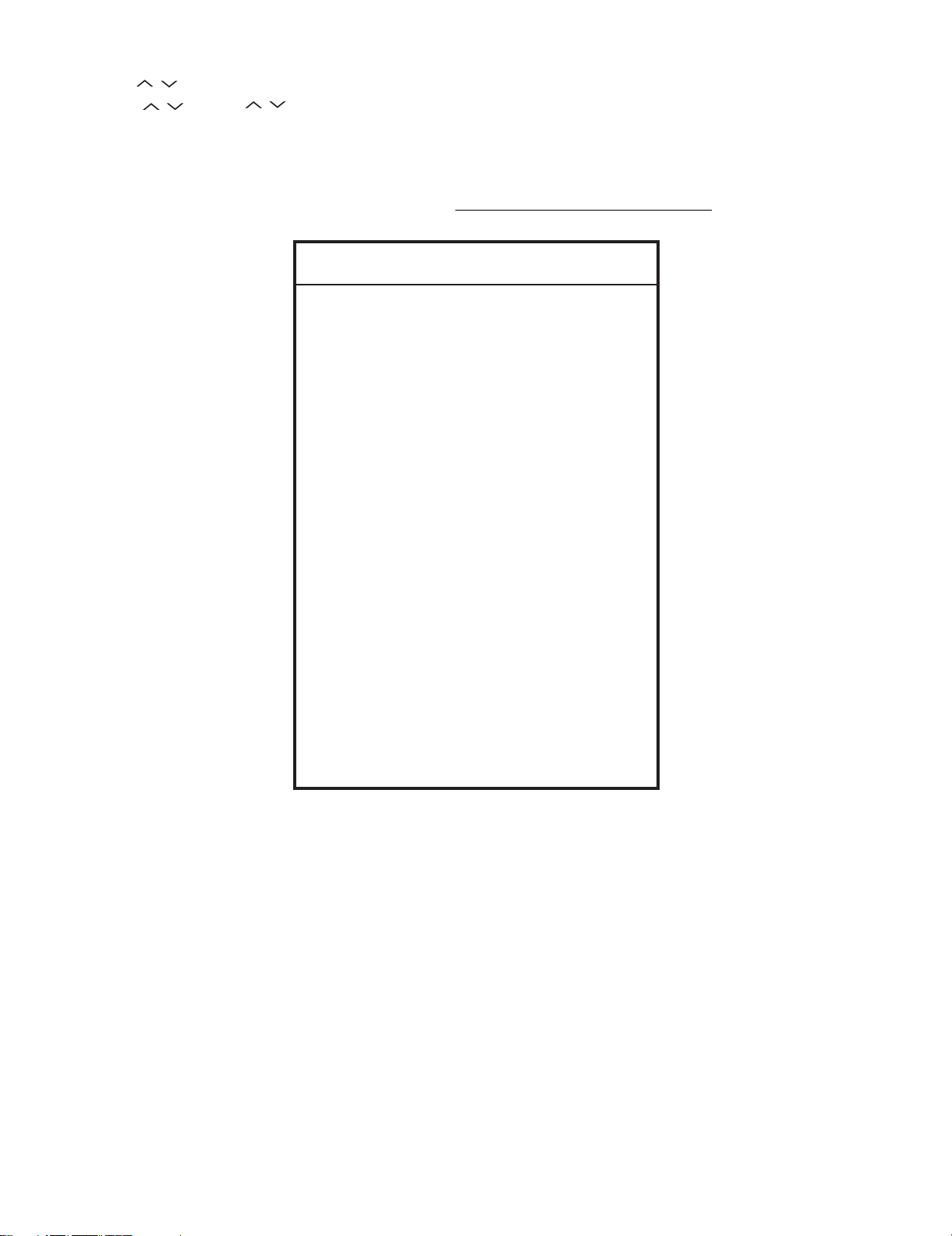
cannot be turned on. Using the cursor ( / ) key, move to the cursor to [LAMP ERROR RESET], Line 8 on adjustment process mode service page 2/16. With the cursor (</>) keys, select the [LAMP ERROR RESET] value. Finally press the cursor (OK) eys to reset the value to “0”.
Table of contents of adjustment process mode Page 2/16
INDUSTRY INIT Enter
INDUSTRY INIT(-Hotel) OFF
HOTEL MODE OFF
Center Acutime
RESET
5H0M
OFF
Backlight Acutime
RESET
LAMP ERROR RESET
OFF
OFF
ADJ PARAM SET Enter
VIC XPOS 0
VIC YPOS 0
VIC SIGNAL TYPE MAIN
VIC READ OFF
Resetting to "0"
3 – 5
8. Public Mode (Hotel Mode)
1. Starting the Public Mode
• T here are two following ways to display the PUBLIC Mode setting screen.
1) On the process adjustment mode screen (2/16), set the “HOTEL MODE” Flag to ON.
LC-32DH65E/S, LC-37DH65E/S
Turn off the power, and turn it on again, pressing the and keys of the main unit at the same time.
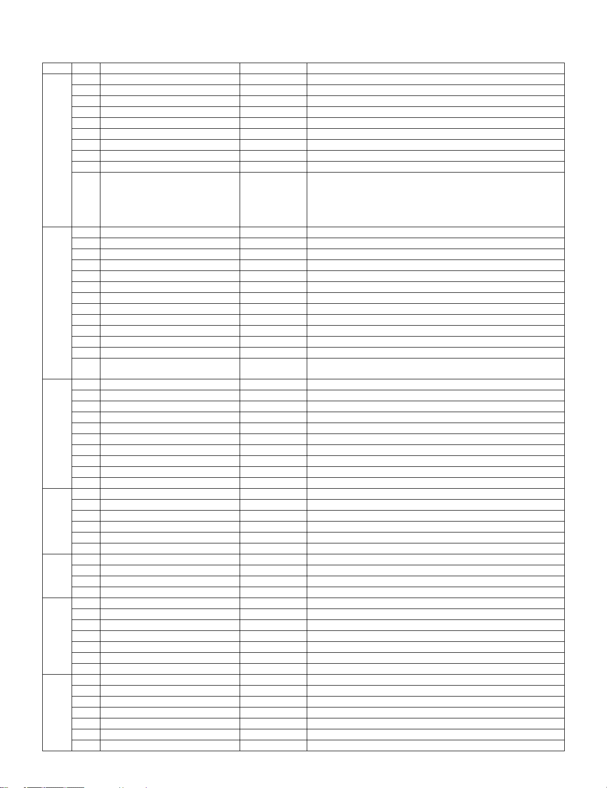
2) Enter the Pass Word, and start the unit.
a) Turn on the power, pressing the and keys of the main unit at the same time.
b) Display the Pass Word input screen.
INPUT
CHANNEL UP
Volume UP
Public Mode Public Mode
Operation procedure
• T he initial input position is the digit at the left end.
9
• For the numeric keys to of R/C, key input is accepted. Input of the other keys is prohibited.
• Change “–” to “*” by inputting the numeric key at the input position, and shift the input position rightward one digit.
• When three digits are completely input, the Pass Word is judged.
c) Check the Pass Word by inputting three digits.
If the Pass Word is , it shifts to the PUBLIC Mode setting screen.
In another case, the screen is erased, and it operates in the ordinary mode.
2. Exiting the Public Mode screen
• There are two following ways to exit the Public Mode setting screen.
1) Turn off the power.
2) Select “Execution” in the PUBLIC_Mode to execute it.
Activate the restart under the set content. Here, the START input SOURCE setting is excluded since this item is referred to only when the
power is turned on.
3. Set value of the Public Mode
• When the shipment setting is done, a set each value in Public Mode is initialized.
(PUBLIC MODE in the process mode Setting of a flag is also initialized)
• Separately, the shipment beginnings when all except for each set value in Public Mode is initialized are provided for a process mode. (INDUSTRY INIT (-HOTEL))
• O nly when turning on the HOTELE MODE item, each setting is effective.
• After it decides it with EXECUTE, it AC OFF/ON it to reflect a set value.
0
2 7
0
Volume UP
Public Mode
3 – 6
LC-32DH65E/S, LC-37DH65E/S
4. Basic operation in the Public Mode
Volume / or Cursor
Channel / or Cursor /
Decision (ok) Execution (Used by the items “Execution” and “RESET”.)
PUBLIC Mode R/C Ordinary operation mode: It enters the PUBLIC Mode.
</>
PUBLIC Mode: It exits the PUBLIC Mode.
Public Mode
POWER ON FIXED [VARIABLE]
SHUT DOWN MODE [NORMAL]
MAXIMUM VOLUME [60]
VOLUME FIXED [VARIABLE]
VOLUME FIXED LEVEL [20]
RC BUTTON [RESPOND]
PANEL BUTTON [RESPOND]
Change or execution of the set value.
Movement to the selected item.
PUBLIC MODE Flag is set to “ON”.
PUBLIC MODE Flag does not change.
Any set item in PUBLIC Mode is not initialized.
MENU BUTTON [ RESPOND]
AV POSITION FIXED [VARIABLE]
ON SCREEN DISPLAY [YES]
INPUT MODE START [NORMAL]
INPUT MODE FIXED [VARIABLE]
LOUD SPEAKER [ON]
RC PATH THROUGH [ OFF]
232C POWON [DISABLE]
HOTELMODE [ON]
RESET
EXECUTE
5. Operation after “RESET”
Select “RESET” in the PUBLIC Mode, and it operates as follows when it is executed (refer to the basic operation).
• The set contents in the PUBLIC mode are initialized.
• It does not exit the PUBLIC mode.
• If “EXCUTE” is not executed, the content that does RESET is not reflected.
3 – 7
Loading...