


KB-6024MS
KB-6024MK
KB-6024MW
SERVICE MANUAL
S27M275KB6025
MICROWAVE DRAWER
MODELS
KB-6024MS/MK/MW KB-6025MS/MK/MW
Melt |
|
Soften |
Easy Open |
|
M I C R O WAV E D R AW E R |
Melt
1
Soften |
Easy Open |
|
M I C R O WAV E D R AW E R |
KB-6024MS pictured |
KB-6025MS pictured |
In the interest of user-safety the unit should be restored to its original condition and only parts identical to those specified should be used.
WARNING TO SERVICE PERSONNEL:
This service manual is intended for use by persons having electrical and mechanical training and a level of knowledge of these subjects generally considered acceptable in the appliance repair trade. Sharp Electronics Corporation cannot be responsible, nor assume any liability, for injury or damage of any kind arising from the use of this manual.
Microwave ovens contain circuitry capable of producing very high voltage and current. Contact with the following parts may result in a severe, possibly fatal, electrical shock. (High Voltage Capacitor, High Voltage Power Transformer, High Voltage Rectifier and Heat sink etc., and Magnetron, High Voltage Harness etc..)
TABLE OF CONTENTS |
|
|
Page |
PRECAUTIONS TO BE OBSERVED BEFORE AND DURING SERVICING TO |
|
AVOID POSSIBLE EXPOSURE TO EXCESSIVE MICROWAVE ENERGY..................... |
INSIDE FRONT COVER |
BEFORE SERVICING........................................................................................................ |
INSIDE FRONT COVER |
WARNING TO SERVICE PERSONNEL................................................................................................................. |
3 |
MICROWAVE MEASUREMENT PROCEDURE..................................................................................................... |
4 |
FOREWORD AND WARNING................................................................................................................................ |
5 |
PRODUCT SPECIFICATIONS................................................................................................................................ |
6 |
SCHEMATICS....................................................................................................................................................... |
10 |
TEST PROCEDURES........................................................................................................................................... |
11 |
TOUCH CONTROL PANEL ASSEMBLY............................................................................................................... |
19 |
MICROWAVE DRAWER DISASSEMBLY............................................................................................................. |
27 |
WIRING DIAGRAMS............................................................................................................................................. |
33 |
PRINTED WIRING BOARDS................................................................................................................................ |
34 |
PARTS LIST.......................................................................................................................................................... |
38 |
PACKING AND ACCESSORIES........................................................................................................................... |
43 |
SHARP ELECTRONICS CORPORATION
This document has been published to be used for after sales service only. The contents are subject to change without notice.

KB-6025MS
KB-6025MK
KB-6025MW
PRECAUTIONSTO BE OBSERVED BEFORE AND DURING SERVICING TO AVOID POSSIBLE EXPOSURE TO EXCESSIVE MICROWAVE ENERGY
(a)Do not operate or allow the oven to be operated with the door open.
(b)Make the following safety checks on all ovens to be serviced before activating the magnetron or other microwave source, and make repairs as necessary: (1) interlock operation, (2) proper door closing, (3) seal and sealing surfaces (arcing, wear, and other damage), (4) damage to or loosening of hinges and latches, (5) evidence of dropping or abuse.
(c)Before turning on microwave power for any service test or inspection within the microwave generating compartments, check the magnetron, wave guide or transmission line, and cavity for proper alignment, integrity, and connections.
(d)Any defective or misadjusted components in the interlock, monitor, door seal, and microwave generation and transmission systems shall be repaired, replaced, or adjusted by procedures described in this manual before the oven is released to the owner.
(e)A microwave leakage check to verify compliance with the Federal Performance Standard should be performed on each oven prior to release to the owner.
BEFORE SERVICING
Before servicing an operative unit, perform a microwave emission check as per the Microwave Measurement Procedure outlined in this service manual.
If microwave emissions level is in excess of the specified limit, contact SHARP ELECTRONICS CORPORATION immediately @1-800-237-4277.
If the unit operates with the door open, service person should 1) tell the user not to operate the oven and 2) contact SHARP ELECTRONICS CORPORATION and Food and Drug Administration's Center for Devices and Radiological Health immediately.
Service personnel should inform SHARP ELECTRONICS CORPORATION of any certified unit found with emissions in excess of 4mW/cm2. The owner of the unit should be instructed not to use the unit until the oven has been brought into compliance.

KB-6024MS
KB-6024MK
KB-6024MW
WARNING TO SERVICE PERSONNEL
Microwave Oven units contain circuitry capable of producing very high voltage and current, contact with following parts may result in a severe, possibly fatal, electrical shock.
(Example)
High Voltage Capacitor, High Voltage Power Transformer, Magnetron, High Voltage Rectifier Assembly, High Voltage Harness, Heating Elements, etc..
Read the Service Manual carefully and follow all instructions.
Before Servicing
1. Disconnect the power supply cord |
, and then |
remove cabinet. |
|
2.Open the drawer and keep it open.
3.Discharge high voltage capacitor.
WARNING: RISK OF ELECTRIC SHOCK. DISCHARGE THE HIGH-VOLTAGE CAPACITOR BEFORE SERVICING.
The high-voltage capacitor remains charged about 60 seconds after the oven has been switched off. Wait for 60 seconds and then short-circuit the connection of the high-voltage capacitor (that is the connecting lead of the high-voltage rectifier) against the chassis with the use of an insulated screwdriver.
When the testing is completed,
1.Disconnect the power supply cord, and then remove covers.
2.Open the drawer and keep it open.
3.Discharge high voltage capacitor.
4.Reconnect the leads to the primary of the power transformer.
5.Reinstall the covers.
6.Reconnect the power supply cord.
7.Run the unit and check all functions.
After repairing
1.Reconnect all leads removed from components during testing.
2.Reinstall the covers.
3.Reconnect the power supply cord.
4.Run the oven and check all functions.
Whenever troubleshooting is performed the power supply must be disconnected. It may, in some cases, be necessary to connect the power supply after the outer case has been removed, in this event:
1.Disconnect the power supply cord, and then remove neccessary covers.
2.Open the drawer and keep it open.
3.Discharge high voltage capacitor.
4.Disconnect the leads to the primary of the power transformer.
5.Ensure that the leads remain isolated from other components and oven chassis by using insulation tape.
6.After that procedure, reconnect the power supply cord.
Microwave ovens should not be operated empty. To test for the presence of microwave energy within a cavity, place a cup of cold water on the oven tray, close the drawer and set the power to HIGH and set the microwave timer for two (2) minutes. When the two minutes has elapsed (timer at zero) carefully check that the water is now hot.If the water remains cold carry out Before Servicing procedure and re-examine the connections to the component being tested.
When all service work is completed and the oven is fully assembled, the microwave power output should be checked and a microwave leakage test should be carried out.

KB-6025MS
KB-6025MK
KB-6025MW
MICROWAVE MEASUREMENT PROCEDURE
A. Requirements:
1)Microwave leakage limit (Power density limit): The power density of microwave radiation emitted by a microwave oven should not exceed 1mW/cm2 at any point 5cm or more from the external surface of the oven, measured prior to acquisition by a purchaser, and thereafter (through the useful life of the oven), 5 mW/cm2 at any point 5cm or more from the external surface of the oven.
2)Safety interlock switches:
Primary interlock relay switch shall prevent microwave radiation emission in excess of the requirement as above mentioned. Secondary interlock relay and door sensing switch shall prevent microwave radiation emission in excess of 5 mW/cm2 at any point 5cm or more from the external surface of the oven.
B. Preparation for testing:
Before beginning the actual measurement of leakage, proceed as follows:
1) Make sure that the actual instrument is operating normally as specified in its instruction booklet.
Important:
Survey instruments that comply with the requirement for instrumentation as prescribed by the performance standard for microwave ovens, 21 CFR 1030.10(c)(3)(i), must be used for testing.
2)Place the load of 275±15 ml (9.8 oz) of tap water initially at 20±5O C (68OF) in the center of the oven cavity.
The water container shall be a low form of 600 ml (20 oz) beaker with an inside diameter of approx. 8.5 cm (3-1/2 in.) and made of an electrically nonconductive material such as glass or plastic.
The placing of this standard load in the oven is important not only to protect the oven, but also to insure that any leakage is measured accurately.
3)Set the cooking control on Full Power Cooking Mode.
4)Close the drawer and select a cook cycle of several minutes. If the water begins to boil before the survey is completed, replace it with 275 ml of cool water.
C. Leakage test:
Closed-drawer leakage test (microwave measurement):
1)Grasp the probe of the survey instrument and hold it perpendicular to the gap between the drawer and the body of the oven.
2)Move the probe slowly, not faster than 1 in./sec. (2.5 cm/sec.) along the gap, watching for the maximum indication on the meter.
3)Check for leakage at the drawer screen, sheet metal seams and other accessible positions where the continuity of the metal has been breached (eg., around the switches, indicator, and vents).
While testing for leakage around the drawer, pull the drawer away from the front of the oven as far as is permitted by the closed latch assembly.
4)Measure carefully at the point of highest leakage and make sure that the highest leakage is no greater than 4mW/cm2, and that the primary interlock switch/secondary interlock relay does turn the oven OFF before any door movement.
NOTE: After servicing, record data on service invoice and microwave leakage report.
SERVICE MANUAL
MICROWAVE DRAWERS
KB-6024MS / KB-6024MK / KB-6024MW
KB-6025MS / KB-6025MK / KB-6025MW
FOREWORD
This Manual has been prepared to provide Sharp Electronics Corp. Service Personnel and Service Information for the MICROWAVE DRAWERS, KB-6024MS, KB-6024MK, KB-6024MW and KB-6025MS, KB-6025MK, KB-6025MW.
It is recommended that service personnel carefully study the entire text of this manual so that they will be qualified to render satisfactory customer service.
Check the interlock switches and the door seal carefully. Special attention should be given to avoid electrical shock and microwave radiation hazard.
WARNING
Never operate the oven until the following points are ensured.
(A)The door is tightly closed.
(B)The door brackets and hinges are not defective.
(C)The door packing is not damaged.
(D)The door is not deformed or warped.
(E)There is not any other visible damage with the oven.
Servicing and repair work must be carried out only by trained service
personnel.
DANGER
Certaininitialpartsareintentionallynotgroundedandpresent a risk of electrical shock only during servicing. Service personnel - Do not contact the following parts while the appliance is energized;
High Voltage Capacitor, PowerTransformer, Magnetron, High Voltage Rectifier Assembly, High Voltage Harness;
If provided, Vent Hood, Fan assembly, Cooling Fan Motor.
All the parts marked “*” on parts list are used at voltages more than 250V.
Removal of the outer wrap gives access to voltage above 250V.
All the parts marked “∆” on parts list may cause undue microwave exposure, by themselves, or when they are damaged, loosened or removed.
SHARP ELECTRONICS CORPORATION
SHARP PLAZA, MAHWAH,
NEW JERSEY 07430-2135
KB-6024MS
KB-6024MK
KB-6024MW
PRODUCT DESCRIPTION
SCHEMATICS
TEST PROCEDURE
TOUCH CONTROL PANEL
MICROWAVE DRAWER
DISSASSEMBLY AND ADJUSTMENT PROCEDURE
WIRING DIAGRAM
PARTS LIST

KB-6025MS
KB-6025MK
KB-6025MW
MICROWAVE DRAWER SPECIFICATION
ITEM |
|
|
DESCRIPTION |
|
|
|
Power Requirements |
20 Volts |
|
|
|
|
|
|
4.5 Amperes, 1000 watts |
|
|
|
|
|
|
60 Hz |
|
|
|
|
|
|
Single phase, 3 wire grounded |
|
|
|
|
|
|
|
|
|
|
||
Power Output |
000 watts (IEC TEST PROCEDURE) |
|
|
|
||
|
Operating frequency of 2450MHz |
|
|
|
||
Cooking Cavity Dimensions |
KB6024 Width |
17-11/32 |
KB6025 Width 17-11/32 |
|
||
|
Height |
5-7/8" |
Height |
5-7/8" |
|
|
1.0 Cubic Feet |
Depth |
17-1/8" |
Depth |
17-1/8" |
|
|
|
|
|
|
|
|
|
Outside Dimensions |
KB6024 Width |
23-7/8" |
KB6025 Width |
30" |
|
|
|
Height |
15-9/32" |
Height |
15-9/32" |
|
|
(Including drawer handle) |
Depth |
26-1/16" |
Depth |
26-1/16" |
|
|
|
|
|
|
|
|
|
Control Complement |
Touch Control System |
|
|
|
|
|
|
Clock ( 1:00 - 12:59 ) |
|
|
|
|
|
|
Timer (0 - 99 min. 99 seconds) |
|
|
|
|
|
|
Microwave Power for Variable Cooking |
|
|
|
||
|
Repetition Rate; |
|
|
|
|
|
|
P-HI................................................... |
|
Full power throughout the cooking time |
|
||
|
P-90..................................................................... |
|
approx. |
90% of Full Power |
|
|
|
P-80..................................................................... |
|
approx. |
80% of Full Power |
|
|
|
P-70..................................................................... |
|
approx. |
70% of Full Power |
|
|
|
P-60..................................................................... |
|
approx. |
60% of Full Power |
|
|
|
P-50..................................................................... |
|
approx. |
50% of Full Power |
|
|
|
P-40..................................................................... |
|
approx. |
40% of Full Power |
|
|
|
P-30 .................................................................... |
|
approx. |
30% of Full Power |
|
|
|
P-20..................................................................... |
|
approx. |
20% of Full Power |
|
|
|
P-10..................................................................... |
|
approx. |
10% of Full Power |
|
|
|
P-0..................................................... |
|
No power throughout the cooking time |
|
||
|
START/MINUTE PLUS pad, Defrost pad, Number selection pad, Keep-warm |
|
||||
|
pad, Power Level pad, Timer/Clock pad, Stop/Clear pad, Sensor Reheat, |
|
||||
|
Sensor Popcorn, Sensor Cook, Open pad, Close pad, Setup/Custom Help, |
|
||||
|
On/Off, Control Lock, Reheat, Soften and Melt. |
|
|
|
||
Oven Cavity Light |
Yes |
|
|
|
|
|
|
|
|
|
|
|
|
Safety Standard |
UL Listed |
FCC Authorized |
|
|
|
|
|
DHHS Rules, CFR, Title 21, Chapter 1, Subchapter J |
|
|
|||
|
|
|
|
|
|
|
GENERAL INFORMATION
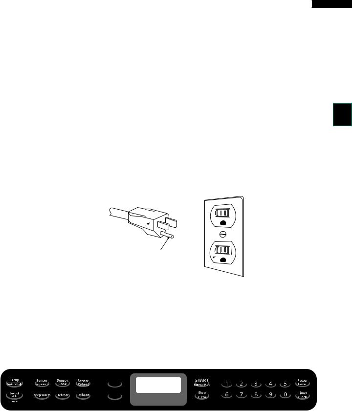
GROUNDING INSTRUCTIONS
KB-6024MS KB-6024MK KB-6024MW
This oven is equipped with a three prong grounding plug. It must be plugged into a wall receptacle that is properly installed and grounded in accordance with the National Electrical Code and local codes and ordinances.
In the event of an electrical short circuit, grounding reduces the risk of electric shock by providing an escape wire for the electric current.
WARNING: |
Improper use of the grounding plug can result in a risk of electric shock. |
Electrical Requirements
The electrical requirements are a 120 volt 60 Hz, AC only, 15 or 20 amp. fused electrical supply. It is recommended that a separate circuit serving only this appliance be provided. When installing this appliance, observe all applicable codes and ordinances.
Where a two-pronged wall-receptacle is encountered, it is the personal responsibility and obligation of the customer to contact a qualified electrician and have it replaced with a properly grounded three-pronged wall receptacle or have a grounding adapter properly grounded and polarized. If an extension cord must be used, it should be a 3-wire, 15 amp. or higher rated cord. Do not drape over a counter top or table where it can be pulled on by children or tripped over accidentally.
CAUTION: DO NOT UNDER ANY CIRCUMSTANCES CUT OR REMOVE THE ROUND GROUNDING PRONG FROM THIS PLUG.
Grounded
Receptacle Box 
3-Pronged  Plug
Plug
Grounding Pin
3-Pronged Receptacle 
Melt |
|
|
|
|
|
|
|
|
|
|
Soften |
|
|
|
|
|
|
|
|
|
|
Easy Open |
|
|
|
|
|
|
|
|||
|
|
|
|
|
|
|
||||
|
|
|
|
|
||||||
|
M I C R O WAV E D R AW E R |
|
||||||||
KB-6024/6025M (Colors may vary)
NOTE:
The directed features are disabled after one minute when the oven is not in use.These features are automatically enabled when the door is opened and closed or the STOP/ CLEAR pad is pressed.

KB-6025MS
KB-6025MK
KB-6025MW
OPERATION
DESCRIPTION OF OPERATING SEQUENCE
The following is a description of component functions during oven operation.
OFF CONDITION
Closing the drawer activates the door sensing switch and secondary interlock switch. (In this condition, the monitor switch contacts are opened.)
When oven is plugged in, 120 volts A.C. is supplied to the control unit. (Page 10).
1.The display will show flashing "EnjoyYour DrawerTouch Clear and Touch Clock".
To set any program or set the clock, you must first touch the STOP/CLEAR pad. The display will clear, and " : " will appear.
COOKING CONDITION
Program desired cooking time by touching the NUMBER pads. Program the power level by touching the POWER LEVEL pad and then a Number pad.
When the START pad is touched, the following operations occur:
1.The contacts of relays are closed and components connected to the relays are turned on as follows.
(For details, refer to Page 10)
RELAY |
CONNECTED COMPONENTS |
RY-1 |
oven lamp/stir fan motor/fan motor |
RY-2 |
power transformer |
2.120 volts A.C. is supplied to the primary winding of the power transformer and is converted to about 3.3 volts A.C. output on the filament winding, and approximately 2370 volts A.C. on the high voltage winding.
3.The filament winding voltage heats the magnetron filament and the H.V. winding voltage is sent to a voltage doubler circuit.
4.The microwave energy produced by the magnetron is channelled through the waveguide into the cavity feedbox, and then into the cavity where the food is placed to be cooked.
5.Upon completion of the cooking time, the power transformer, oven lamp, etc. are turned off, and the generation of microwave energy is stopped. The oven will revert to the OFF condition.
6.When the drawer is opened during a cook cycle, the monitor switch, door sensing switch, secondary interlock switch, relay (RY1) and primary interlock relay are activated with the following results.The circuits to the stir fan motor, the cooling fan motor, and the high voltage componentsarede-energized,theovenlampremainson, and the digital read-out displays the time still remaining in the cook cycle when the door was opened.
7.The monitor switch electrically monitors the operation of
the secondary interlock switch and secondary interlock relay and is mechanically associated with the drawer so that it will function in the following sequence.
8.When the drawer opens from the closed position, the primary interlock relay (RY2) and secondary interlock switch open their contacts. And contacts of the relay (RY1) remains closed.Then the monitor switch contacts close.
9.When the drawer is closed from the open position, the monitor switch contacts open first. Then the contacts of the secondary interlock switch and door sensing switch close. And contacts of the relay (RY1) open.
If the secondary interlock switch and primary interlock relay (RY2) fail with the contacts closed when the drawer is opened, the closing of the monitor switch contacts will form a short circuit through the fuse, secondary interlock switch, relay (RY1) and secondary interlock relay (RY2), causing the fuse to blow.
POWER LEVEL P-0 TO P-90 COOKING
When Variable Cooking Power is programmed, the 120 volts A.C. is supplied to the power transformer intermittently through the contacts of relay (RY-2) which is operated by the control unit within a 32 second time base. Microwave power operation is as follows:
VARI-MODE |
ON TIME |
OFF TIME |
Power 10(P-HI) |
32 sec. |
0 sec. |
(100% power) |
|
|
Power 9(P-90) |
30 sec. |
2 sec. |
(approx. 90% power) |
|
|
Power 8(P-80) |
26 sec. |
6 sec. |
(approx. 80% power) |
|
|
Power 7(P-70) |
24 sec. |
8 sec. |
(approx. 70% power) |
|
|
Power 6(P-60) |
22 sec. |
10 sec. |
(approx. 60% power) |
|
|
Power 5(P-50) |
18 sec. |
14 sec. |
(approx. 50% power) |
|
|
Power 4(P-40) |
16 sec. |
16 sec. |
(approx. 40% power) |
|
|
Power 3(P-30) |
12 sec. |
20 sec. |
(approx. 30% power) |
|
|
Power 2(P-20) |
8 sec. |
24 sec. |
(approx. 20% power) |
|
|
Power 1(P-10) |
6 sec. |
26 sec. |
(approx. 10% power) |
|
|
Power 0(P-0) |
0 sec. |
32 sec. |
(0% power) |
|
|
Note: The ON/OFF time ratio does not correspond with the percentage of microwave power, because approx.2 seconds are needed for heating of the magnetron filament.

SENSOR COOKING CONDITION
Using the SENSOR function, food is cooked without figuring time, power level or quantity. When the oven senses enough steam from the food, it relays the information to its microprocessor which will calculate the remaining cooking time and power level needed for best results. When the food is cooked, water vapor is developed. the sensor "senses" the vapor and its resistance increase gradually. When the resistance reaches the value set according to the menu, supplementary cooking is started.
The time of supplementary cooking is determined by experiment with each food category and inputted into the LSI. An example of how sensor works: (Potatoes)
1.Potatoes at room temperature. Vapor is emitted very slowly.
MICROWAVE
KB-6024MS
KB-6024MK
KB-6024MW
2.The coil of shut-off relay (RY-1) is energized, but the power transformer is not turned on.
3.After about 16 seconds, the cook relay (RY-2) is energized. The power transformer is turned on, microwave energy is produced and first stage is started. The 16 seconds is the cooling time required to remove any vapor from the oven cavity and sensor.
NOTE: During this first stage, do not open the drawer or touch STOP/CLEAR pad.
4.When the sensor detects the vapor emitted from the food, the display switches over to the remaining cooking time and the timer counts down to zero.
At this time, the drawer may be opened to stir, turn or season food.
5.When the timer reaches zero, an audible signal sounds. The shut-off relay and cook relay are de-energized and the power transformer, oven lamp, etc. are turned off.
6.Opening the drawer or touching the STOP/CLEAR pad, the time of the day will reappear on the display and the oven will revert to an OFF condition. When the timer reaches zero, an audible signal sounds.
2.Heat Potatoes. Moisture and humidity is emitted very rapidly. You can smell the aroma as it cooks.
AH SENSOR
MICROWAVE
3.Sensor detects moisture and humidity and calculates cooking time and variable power.
Cooking Sequence.
1. Touch one of the SENSOR pads.
NOTE: The oven should not be operated on sensor immediately after plugging in the unit. Wait two
minutes before cooking on SENSOR.

KB-6025MS KB-6025MK KB-6025MW
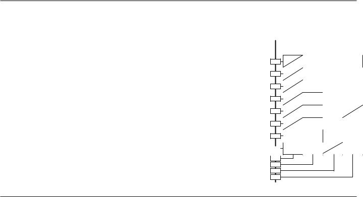
SCHEMATIC (OFF CONDITION)
|
|
N |
|
|
.Hz 60 |
120VAC |
NRG |
H |
|
|
|
|
|
|
|
|
|
|
|
viewkbac |
|
|
(R E D) |
|
|
WHT |
N |
GND |
RED |
|
L |
|
|
|
|
|
|
|
|
|
|
wireHOT |
|||||
|
|
|
|
|
|
|
|
|
|
|
|
|
|
|
|
|
|
|
|
|
|||
|
|
|
"TO SOURCE" |
|
|
|
|
"TO SOURCE" |
|
|
|
|
|
|
|
|
|
|
|
|
|
||
MICROWAVE DRAWER |
SWITCHINTELOCKSECONDARY |
|
|
.O.NB1A1 |
|
|
PRIMARYA5 |
INTERLOCKRMEORFANSTRETAGVOLOWL GORGORLKB COM RELAYH11 |
|
|
|
|
:SENOT |
DRAWERMICROWAVE CireW/uitsircC1.CLOSE-OPENDOORolors s ubjec t to c hange without notic e. MOTOR isthaterminalT2.loc ated to the right s ide on the lamp s oc ket's |
onneccbetmusted to neutral wire. |
modelsertaincOnly3. us e the abs olute humidity s ens or |
formerransTowerP4. (F inis h L ead) terminal mus t be c onnec ted to |
||||||
YRG YRG |
OMC.O.N |
|
LKB GOR |
|
RY2 |
|
DER LKB |
H9 |
DM |
||||||||||||||
|
NOIS |
|
|
|
|
|
|
|
|
FUSE |
|
|
|
|
|
|
|
|
|
|
|
|
|
|
|
|
|
|
|
|
|
|
20A |
|
|
|
|
|
|
|
|
|
|
|
|
|
|
|
|
|
|
RESISTOR 470 k? |
1/2W |
|
|
|
|
|
|
|
|
|
|
|
|
|
|
|
|||
|
E |
|
|
|
|
|
|
|
|
|
|
|
|
|
|
|
|
|
|
|
|
|
|
|
TE IL F |
|
|
LINE CROSS CAPACITOR 1.0 ?F 275V |
|
|
|
|
|
|
|
|
|
|
|
|
|
|
|||||
|
|
|
|
NOISE SUPRESSION COIL |
|
|
|
|
|
|
|
|
|
|
|
|
|
|
|
||||
|
R |
|
|
|
|
|
|
|
|
|
|
|
|
|
|
|
|
|
|
|
|
|
|
|
|
|
LINE BYPASS CAPACITOR |
|
LINE BYPASS CAPACITOR |
|
|
|
|
|
|
|
|
|
|
|
|
|
|||||
|
|
|
0.0033 ?F 250V |
|
|
0.0033 ?F 250V |
|
|
|
|
|
|
|
|
|
|
|
|
|
|
|||
|
|
|
"TO LOAD" |
|
|
|
|
"TO LOAD" |
|
THERMAL |
|
|
|
|
|
|
|
|
|
|
|
||
|
|
WHT WHT |
|
|
|
|
|
|
|
D E R |
OUT - CUT |
OVEN |
|
|
|
|
|
|
|
|
|
|
|
|
|
|
|
|
|
|
|
|
A7 |
|
- CUT |
THERMAL |
MG |
N501 C N501 C 3 1 |
|
|
HING WITC S |
|
|
|
|
|
|
|
|
|
|
WHT |
|
|
|
|
|
B LK |
|
|
|
|
|
|
|
|
|
|
|
||
|
|
|
|
|
|
|
|
|
|
OR G |
|
|
|
|
|
|
|
|
|
|
|
|
|
|
|
|
|
|
|
|
|
|
|
|
|
|
|
|
|
|
GE R |
|
|
|
|
|
|
|
|
|
|
|
|
|
|
|
|
|
|
|
|
G R N |
|
|
ULATOR |
|
|
|
|
|
|
|
|
|
|
|
|
|
|
|
|
|
|
|
|
|
|
|
|
|
|
|
|
|
|
|
|
|
HUMIDITY |
|
|
|
|
|
|
|
|
|
C |
|
|
|
|
|
|
|
|
|
|
|
|
|
SENSOR |
|
F1 |
|
|
|
|
|
|
|
|
|
|
|
|
|
|
|
|
||
|
|
|
|
|
|
|
|
|
|
|
|
|
C 1 N502 2 |
|
C |
|
|
|
|
|
|
||
|
|
|
|
|
|
|
|
|
|
|
GOR GOR |
|
|
|
|
|
|
|
|
|
|||
|
|
|
|
|
|
F2 |
|
|
|
|
|
R E D |
E1N502 E3 |
|
N502 3 |
|
|
|
|
|
|
||
|
|
|
|
|
|
|
|
|
|
|
|
|
|
|
|
|
|
|
|
|
|||
|
|
|
|
|
|
|
|
|
|
|
|
|
|
|
|
|
|
|
|
|
|
||
|
|
WHT WHT |
|
|
|
F3 |
|
|
ONTRC |
|
|
|
|
|
|
|
|
|
|
|
|
|
|
|
|
|
|
|
|
|
RY4 |
|
|
|
|
|
RY5 |
|
|
|
|
|
|
|
|
||
|
|
|
|
|
|
|
|
|
|
|
|
|
|
|
|
|
|
|
|
|
|
||
|
|
|
|
|
|
|
|
|
|
|
|
|
|
|
|
|
|
|
|
|
|
|
|
|
|
|
WHT |
|
|
A3 |
|
|
OL |
|
|
|
|
|
|
|
N1 |
|
|
|
|
|
|
|
|
|
WHT |
FM |
B LK |
|
|
|
|
|
|
|
|
|
R E D |
|
|
|
|
|
|
||
|
|
|
|
|
|
|
|
UNIT |
|
|
|
|
|
|
|
|
|
|
|
|
|
|
|
|
|
|
FAN MOTOR |
|
|
RY3 |
|
|
|
|
|
|
|
N2 OR G |
|
|
|
|
|
|
|||
|
|
|
|
|
|
|
|
|
|
|
|
|
|
|
|
|
|
|
|||||
|
|
|
WHT |
S M |
B R N |
|
|
|
|
|
|
|
|
|
|
|
B LU |
|
|
|
|
|
|
|
|
|
|
|
|
|
|
|
|
|
|
|
|
|
|
N3 |
|
|
|
|
|
|
|
|
|
|
|
|
|
|
|
RY1 |
|
|
|
|
|
|
|
|
|
|
|
|
|
|
|
|
|
|
STIRRER |
|
|
|
|
|
|
|
|
|
|
Y LW |
|
|
|
|
|
|
|||
|
|
|
|
|
|
|
|
|
|
|
|
|
|
|
|
|
|
|
|
|
|||
|
|
|
MOTOR |
|
|
|
|
|
|
|
|
|
|
|
N4 |
|
|
|
|
|
|
||
|
|
|
G R Y |
|
|
|
|
|
|
|
|
|
|
|
|
|
N5 B LK |
|
|
|
|
|
|
|
|
|
|
|
|
|
|
|
|
|
|
|
|
|
|
|
|
|
|
|
|
|
|
|
|
|
WHT |
|
OR G |
B LK |
|
|
|
|
|
|
|
|
|
|
|
|
|
DOOR SENSING SWITCH |
|
|
|
|
|
|
G R Y |
OL |
|
|
|
|
N.O. |
|
|
|
|
M1 |
RG RG |
|
|
|
|||||
|
|
|
|
|
COM |
|
|
|
|
|
|
|
|
|
|
|
|||||||
|
|
|
|
|
|
|
|
|
|
E R E R |
|
|
|
|
|
M3 |
G R N |
|
|
|
|
|
|
|
|
|
OVEN LAMP |
|
|
|
|
|
D D |
|
|
|
|
|
|
G R N |
|
|
|
|
|
||
|
|
|
|
|
|
|
|
|
|
|
|
|
|
WHT |
|
|
|
|
|
||||
|
|
|
|
|
|
|
|
|
|
|
|
|
|
|
|
|
G R N |
|
|
|
|
|
|
|
|
|
|
|
|
|
|
|
|
|
|
|
|
|
|
|
|
N N |
|
|
|
|
|
|
|
|
WHT |
|
|
|
COM |
N.C. |
R E D |
|
|
|
|
|
|
|
|
|
|
|
|
|
|
|
|
|
G R Y |
|
|
|
|
|
|
|
|
|
|
|
|
DOOR POSITION SWITCH FRONT |
|
|
|
||||
|
|
|
G R Y |
|
|
|
|
|
|
|
|
|
|
|
|
|
G R Y |
G R N |
|
|
|
|
|
|
|
|
|
|
|
|
|
|
|
|
|
|
|
|
|
|
|
|
|
|
|
||
|
|
|
|
|
|
|
MONITOR SWITCH |
|
|
|
|
|
|
|
G R N |
|
|
|
|
|
|||
|
|
|
|
|
|
|
|
|
|
|
|
|
|
|
|
|
|
|
|
||||
|
|
|
|
|
|
|
|
|
R E D |
|
|
|
|
|
|
M4 |
|
|
|
|
|
|
|
|
|
|
|
|
|
|
|
|
|
|
|
|
|
|
|
|
|
|
|
|
|
|
|
|
|
|
G R Y |
|
|
|
POWER TRANSFORMER |
|
|
|
|
|
|
|
|
|
DOOR POSITION SWITCH REAR |
|
|
|
|||
|
|
|
|
|
|
|
|
|
|
|
|
|
|
|
|
|
B LU |
G R N |
|
|
|
|
|
|
|
|
|
|
|
|
|
|
|
|
|
|
|
|
|
|
|
|
|
|
|
||
|
|
|
|
|
|
|
|
|
|
|
|
|
|
|
|
|
M5 |
|
|
|
|
|
|
|
|
|
CAPACITOR |
|
|
|
|
|
|
|
|
|
|
|
|
|
|
|
|
|
|
|
|
|
|
|
1.00 ?F |
|
|
|
|
|
|
|
|
|
|
|
|
|
|
|
|
|
|
|
|
|
|
|
AC 2300V |
|
|
|
|
|
|
|
|
|
|
|
|
|
|
|
|
|
|
|
|
H.V. RECTIFIER |
MAGNETRON |
10
|
TEST PROCEDURES |
|
PROCEDURE |
COMPONENT TEST |
|
LETTER |
||
|
||
A |
TOUCH CONTROL PANEL ASSEMBLY TEST |
KB-6024MS KB-6024MK KB-6024MW
The touch control panel consists of circuits including semiconductors such as LSI, ICs, etc. Therefore, unlike conventional microwave ovens, proper maintenance cannot be performed with only a voltmeter and ohmmeter.
In this service manual, the touch control panel assembly is divided into three units, Control Unit, Keyboard Unit and Power Unit, and troubleshooting by unit replacement is described according to the symptoms indicated.
Before testing,
1)Disconnect the power supply cord, and then disassemble as per "MICROWAVE DRAWER DISASSEMBLY" page 27.
2)Open the drawer and block it open.
3)Discharge high voltage capacitor.
4)Disconnect the leads to the primary of the power transformer.
5)Ensure that these leads remain isolated from other components and oven chassis by using insulation tape.
1.Keyboard Unit. NOTE ;
1)Check Keyboard unit connection before replacement.
2)Reconnect all leads removed from components during testing.
3)Re-install the covers.
4)Reconnect the power supply cord after the covers are installed.
5)Run the oven and check all functions.
The following symptoms indicate a defective keyboard unit.
a)When touching the pads, a certain pad produces no signal at all.
b)When touching a number pad, two figures or more are displayed.
c)When touching the pads, sometimes a pad produces no signal. If the Keyboard unit is defective.
1) Disconnect the power supply cord, and then remove covers. 2) Open the drawer and block it open.
3) Discharge high voltage capacitor.
4) Replace the Keyboard unit.
5) Reconnect all leads removed from components during testing.
6) Re-install the covers.
7) Reconnect the power supply cord after the covers are installed. 8) Run the oven and check all functions.
2.Control Unit
The following symptoms indicate a defective control unit. Before replacing the control unit, perform the Keyboard unit test (Procedure B) to determine if control unit is faulty.
2-1 In connection with indicators
a)At a certain digit, all or some segments do not light up.
b)At a certain digit, brightness is low.
c)Only one indicator does not light.
d)The corresponding segments of all digits do not light up; or they continue to light up.
e)Wrong figure appears.
f)A certain group of indicators do not light up.
g)The figure of all digits flicker.
2-2 Other possible problems caused by defective control unit.
a)Buzzer does not sound or continues to sound.
b)Clock does not operate properly.
c)Cooking is not possible.
3.Power Unit or Touch Control Transformer
a)Fan motor, stirrer motor, oven lamp or electrical parts do not turn on or do not turn off.
b)Digital display on the control unit does not show anything.
When testing is completed,
1)Disconnect the power supply cord, and then disassemble as per "MICROWAVE DRAWER DISASSEMBLY" page 27.
2)Open the drawer and block it open.
3)Discharge high voltage capacitor.
11
|
|
|
|
KB-6025MS |
|
||
KB-6025MK |
TEST PROCEDURES |
||
KB-6025MW |
|||
|
PROCEDURE |
COMPONENT TEST |
|
|
LETTER |
||
|
|
||
4)Reconnect all leads removed from components during testing.
5)Re-install the covers.
6)Reconnect the power supply cord after the covers are installed.
7)Run the oven and check all functions.
BKEY UNIT TEST
1.Disconnect the power supply cord, and then remove outer case.
2.Open the drawer and block it open.
3.Discharge high voltage capacitor.
4.If the display fails to clear when the STOP/CLEAR pad is depressed, first verify the flat ribbon cable is making good contact, verify that the door sensing switch (stop switch) operates properly; that is the contacts are closed when the drawer is closed and open when the drawer is open. If the door sensing switch (stop switch) is good, disconnect the flat ribbon cable that connects the key unit to the control unit and make sure the drawer sensing switch is closed (either close the drawer or short the door sensing switch connecter). Use the Key unit matrix indicated on the control panel schematic and place a jumper wire between the pins that correspond to the STOP/CLEAR pad making momentary contact. If the control unit responds by clearing with a beep the key unit is faulty and must be replaced. If the control unit does not respond, it is faulty and must be replaced. If a specific pad does not respond, the above method may be used (after clearing the control unit) to determine if the control unit or key pad is at fault.
5.Reconnect all leads removed from components during testing.
6.Re-install the outer case (cabinet).
7.Reconnect the power supply cord after the outer case is installed.
8.Run the oven and check all functions.
|
<KEY UNIT> |
|
|
||
J-12 |
|
6 |
9 |
TIMER |
|
|
CLOCK |
||||
J-11 |
|
1 |
8 |
0 |
|
J-10 |
|
2 |
3 |
5 |
|
J-9 |
|
7 |
4 |
POWER |
|
|
LEVEL |
||||
|
|
|
|
||
J-8 |
|
SENSOR |
MELT |
|
|
|
REHEAT |
|
|||
|
|
|
|
||
|
|
SENSOR |
SENSOR |
SET UP |
|
J-7 |
|
CUSTOM |
|||
|
COOK |
POPCORN |
|||
|
|
HELP |
|||
|
|
|
|
||
|
|
|
KEEP |
CONTROL |
|
J-6 |
REHEAT |
DEFROST |
LOCK |
||
WARM |
|||||
|
|
|
ON/OFF |
||
|
|
|
|
||
J-5 |
STOP/ |
START/MINUTE |
SOFTEN |
||
CLEAR |
PLUS |
||||
|
|
|
|||
|
|
|
|
|
|
J-4
J-3
J-2
J-1
CRELAY TEST
1.Disconnect the power supply cord, and then remove outer case.
2.Open the door and block it open.
3.Discharge high voltage capacitor.
4.Disconnect the leads to the primary of the power transformer.
5.Ensure that these leads remain isolated from other components and oven chassis by using insulation tape.
6.After that procedure, re-connect the power supply cord.
7.Remove the outer case and check voltage between Pin Nos. 5 and 7 of the 4 pin connector (CN-A) on the power unit with an A.C. voltmeter.
The meter should indicate 120 volts, if not check oven circuit. RY1, RY2, RY3 and RY4 Relay Test
These relays are operated by D.C. voltage
Check voltage at the relay coil with a D.C. voltmeter during the microwave cooking operation.
DC. voltage indicated |
|
Defective relay. |
|||
DC. voltage not indicated |
Check diode which is connected to the relay coil.If diode is good, |
||||
|
|
|
control unit is defective. |
||
RELAY SYMBOL |
|
OPERATIONAL VOLTAGE |
CONNECTED COMPONENTS |
|
|
RY1 |
|
|
Approx. 26V D.C. |
Oven lamp / Common |
|
RY2 |
|
|
Approx. 25V D.C. |
Power transformer |
|
RY3 |
|
|
Approx. 26V D.C. |
Stirrer motor |
|
RY4 |
|
|
Approx. 26V D.C. |
Fan motor |
|
RY5 |
|
|
Approx. 26V D.C. |
Switching regurator for drawer motor |
|
8.Disconnect the power supply cord, and then remove outer case. 9.Open the door and block it open.
10.Discharge high voltage capacitor.
12

TEST PROCEDURES
PROCEDURE |
COMPONENT TEST |
|
LETTER |
||
|
KB-6024MS KB-6024MK KB-6024MW
12.Re-install the outer case (cabinet).
13.Reconnect the power supply cord after the outer case is installed. 14.Run the oven and check all function.
D |
DEFROST TEST |
|
|
|
|
|
|
|
||
|
WARNING : The oven should be fully assembled before following procedure. |
|||||||||
|
(1) |
Place one cup of water in the center of the tray in the oven cavity. |
|
|
||||||
|
(2) |
Close the drawer, touch the Defrost pad. Then select Steaks/Chops by touching the number pad |
||||||||
|
|
2. And touch the number pad 5. (Now, weight 0.5lb is set.) And then touch the start pad. |
||||||||
|
(3) |
The oven is in Defrost cooking condition. |
|
|
|
|
||||
|
(4) |
The oven will operate as follows |
|
|
|
|
|
|||
|
|
|
|
|
|
|
|
|
|
|
|
|
|
WEIGHT |
1ST STAGE |
2ND STAGE |
3RD. STAGE |
|
|||
|
|
|
|
LEVEL |
TIME |
LEVEL |
TIME |
LEVEL |
TIME |
|
|
|
|
0.5lb |
60% |
20sec. |
40% |
20sec. |
30% |
45sec. |
|
|
(5) If improper operation is indicated, the control unit is probably defective and should be checked. |
|||||||||
|
|
|||||||||
E |
PROCEDURES TO BE TAKEN WHEN THE FUSE ON THE PRINTED WIRING BOARD (PWB) IS OPEN. |
|||||||||
To protect the electronic circuits, this model is provided with a fuse added to the primary on the PWB.
1.Fuse check and repairs.
1)Disconnect the power supply cord.
2)Remove the outer case cabinet.
3)Open the door and block it open.
4)Discharge high voltage capacitor.
5)If the Fuse is blown, replace power unit.
6)Make a visual inspection of the varistor. Check for burned damage. If the varistor has been burned, replace the power unit.
7)Examine the touch control transformer with a tester for the presence of layer short-circuit (check the primary coil resistance which is approximately 151.6Ω ± 10%). If any abnormal condition is detected, replace the touch control transformer.
8)Reconnect all leads removed from components during testing.
9)Re-install the outer case (cabinet).
10)Reconnect the power supply cord after the outer case is installed.
11)Run the oven and check all functions.
2.Follow the troubleshooting guide given below, if indicator does not light up after above check and repairs are finished.
1)Disconnect the power supply cord.
2)Remove the outer case cabinet.
3)Open the door and block it open.
4)Discharge high voltage capacitor.
5)Disconnect the leads to the primary of the power transformer.
6)Ensure that these leads remain isolated from other components and oven chassis by using insulation tape.
7)After that procedure, re-connect the power supply cord.
8)Follow the troubleshooting guide given below for repair.
STEPS |
OCCURRENCE |
CAUSE OR CORRECTION |
1 |
The rated AC voltage is not present between |
Check supply voltage and oven power cord. |
|
Pin Nos. 5 and 7 of the 4-pin connecter (CN-A). |
|
|
|
|
2 |
The rated AC voltage is present at primary |
Touch control transformer or secondary circuit defective. |
|
side of touch control transformer. |
Check and replace touch control transformer or power unit |
.
13

KB-6025MS
KB-6025MK
KB-6025MW
TEST PROCEDURES
PROCEDURE |
COMPONENT TEST |
|
LETTER |
||
|
11)Discharge high voltage capacitor.
12)Reconnect all leads removed from components during testing.
13)Re-install the outer case (cabinet).
14)Reconnect the power supply cord after the outer case is installed.
15)Run the oven and check all functions.
F |
AH SENSOR TEST |
|
|
Checking the initial sensor cooking condition |
|
|
WARNING : The oven should be fully assembled before following procedure. |
|
|
(1) |
The oven should be plugged in at least two minutes before sensor cooking. |
|
(2) |
Room temperature should not exceed 95οF (35οC). |
|
(3) |
The unit should not be installed in any area where heat and steam are generated.The unit should not be |
|
|
installed, for example, next to a conventional surface unit. Refer to the “INSTALLATION INSTRUCTIONS” |
|
|
of the operation manual. |
|
(4) |
Exhaust vents are provided on the back of the unit for proper cooling and air flow in the cavity. To permit |
|
|
adequate ventilation, be sure to install so as not to block these vents. There should be some space for |
|
|
air circulation. |
|
(5) |
Be sure the exterior of the cooking container and the interior of the oven are dry. Wipe off any moisture |
|
|
with a dry cloth or paper towel. |
|
(6) |
The Sensor works with food at normal storage temperature. For example, chicken pieces would be at |
|
|
refrigerator temperature and canned soup at room temperature. |
|
(7) |
Avoid using aerosol sprays or cleaning solvents near the oven while using Sensor settings. The sensor |
|
|
will detect the vapor given of by the spray and turn off before food is properly cooked. |
|
(8) |
If the sensor has not detected the vapor of the food, ERROR will appear and the oven will shut off. |
Water load cooking test
WARNING : The oven should be fully assembled before following procedure.
Make sure the oven has been plugged in at least two minutes before checking sensor cook operation. The cabinet should be installed and screws tightened.
(1)Fill approximately 200 milliliters (7.2 oz) of tap water in a 1000 milliliter measuring cup.
(2)Place the container on the center of tray in the oven cavity.
(3)Close the drawer.
(4)Touch the TIMER/CLOCK pad once, the POWER LEVEL pad twice and the START pad once. And touch the number pads 1 once and the number pad 4 once. Now, the oven is in the sensor cooking condition, and "AH20" and "ON" will appear in the display.
(5)The oven will operate for the first 16 seconds, without generating microwave energy.
NOTE: ERROR will appear if the door is opened or STOP/CLEAR pad is touched during first stage of sensor cooking.
(6) After approximately 16 seconds, microwave energy is produced.
If ERROR is displayed or the oven does not turn off, replace the AH sensor or check the control unit, refer to explanation below. If the oven stops after 5 minutes and no ERROR code is displayed, then the AH sensor is normal. Check other parts except the AH sensor.
TESTING METHOD FOR AH SENSOR AND/OR CONTROL UNIT
To determine if the sensor is defective, the simplest method is to replace it with a new replacement sensor.
(1)Disconnect the power supply cord, and then disassemble as per "MICROWAVE DRAWER DISASSEMBLY" page 25.
(2)Open the drawer and block it open.
(3)Discharge high voltage capacitor.
(4)Remove the AH sensor.
(5)Install the new AH sensor.
(6)Reconnect all leads removed from components during testing.
(7)Re-install the covers.
(8)Reconnect the power supply cord after the covers are installed.
(9)Reconnect the oven to the power supply and check the sensor cook operation as follows: 9-1. Fill approximately 200 milliliters (7.2 oz) of tap water in a 1000 milliliter measuring cup.
14
 Loading...