


SHARP KB3425L, KB-3425JK, KB-3425JW, KB-4425JS, KB-442 Service Manual
...KB-3425LS/K/W
KB-4425LS/K/W
SERVICE MANUAL
S66R264KB442L
FREE STANDING/SLIDE-IN RANGE
WITH MICROWAVE DRAWER
MODELS
KB-3425LS KB-3425LK KB-3425LW
KB-4425LS KB-4425LK KB-4425LW
KB-4425LW pictured
WARNING TO SERVICE PERSONNEL:
This service manual is intended for use by persons having electrical and mechanical training and a level of knowledge of these subjects generally considered acceptable in the appliance repair trade. Sharp Electronics Corporation cannot be responsible, nor assume any liability, for injury or damage of any kind arising from the use of this manual.
Microwave ovens contain circuitry capable of producing very high voltage and current. Contact with the following parts may result in a severe, possibly fatal, electrical shock. (High Voltage Capacitor, High Voltage Power Transformer, High Voltage Rectifier and Heat sink etc., and Magnetron, High Voltage Harness etc..)
TABLE OF CONTENTS |
|
|
Page |
PRECAUTIONS TO BE OBSERVED BEFORE AND DURING SERVICING TO |
|
AVOID POSSIBLE EXPOSURE TO EXCESSIVE MICROWAVE ENERGY..................... |
INSIDE FRONT COVER |
BEFORE SERVICING........................................................................................................ |
INSIDE FRONT COVER |
WARNING TO SERVICE PERSONNEL................................................................................................................. |
3 |
MICROWAVE MEASUREMENT PROCEDURE..................................................................................................... |
5 |
FOREWORD AND WARNING................................................................................................................................ |
7 |
PRODUCT SPECIFICATIONS................................................................................................................................ |
8 |
POWER CONNECTION....................................................................................................................................... |
10 |
ANTI-TIP DEVICE................................................................................................................................................. |
12 |
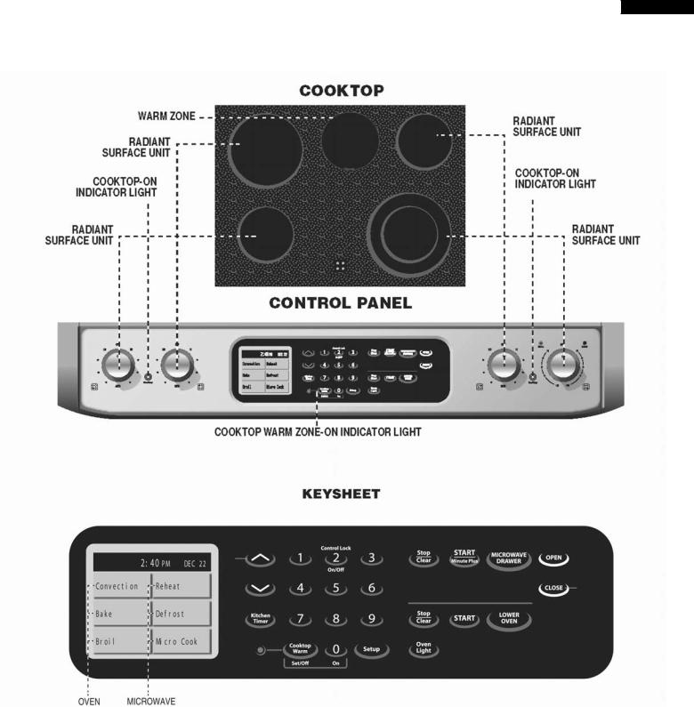
CONTROL LAYOUT.............................................................................................................................................. |
13 |
SCHEMATICS....................................................................................................................................................... |
14 |
TEST PROCEDURES........................................................................................................................................... |
18 |
TOUCH CONTROL PANEL ASSEMBLY............................................................................................................... |
29 |
OVEN/MICROWAVE DRAWER DISASSEMBLY.................................................................................................. |
40 |
WIRING DIAGRAMS............................................................................................................................................. |
52 |
PRINTED WIRING BOARDS................................................................................................................................ |
58 |
PARTS LIST.......................................................................................................................................................... |
63 |
PACKING AND ACCESSORIES........................................................................................................................... |
74 |
SHARP ELECTRONICS CORPORATION
This document has been published to be used for after sales service only. The contents are subject to change without notice.

KB-3425LS/K/W
KB-4425LS/K/W
PRECAUTIONSTO BE OBSERVED BEFORE AND DURING SERVICING TO AVOID POSSIBLE EXPOSURE TO EXCESSIVE MICROWAVE ENERGY
(a)Do not operate or allow the oven to be operated with the door open.
(b)Make the following safety checks on all ovens to be serviced before activating the magnetron or other microwave source, and make repairs as necessary: (1) interlock operation, (2) proper door closing, (3) seal and sealing surfaces (arcing, wear, and other damage), (4) damage to or loosening of hinges and latches, (5) evidence of dropping or abuse.
(c)Before turning on microwave power for any service test or inspection within the microwave generating compartments, check the magnetron, wave guide or transmission line, and cavity for proper alignment, integrity, and connections.
(d)Any defective or misadjusted components in the interlock, monitor, door seal, and microwave generation and transmission systems shall be repaired, replaced, or adjusted by procedures described in this manual before the oven is released to the owner.
(e)A microwave leakage check to verify compliance with the Federal Performance Standard should be performed on each oven prior to release to the owner.
BEFORE SERVICING
Before servicing an operative unit, perform a microwave emission check as per the Microwave Measurement Procedure outlined in this service manual.
If microwave emissions level is in excess of the specified limit, contact SHARP ELECTRONICS CORPORATION immediately @1-800-237-4277.
If the unit operates with the door open, service person should 1) tell the user not to operate the oven and 2) contact SHARP ELECTRONICS CORPORATION and Food and Drug Administration's Center for Devices and Radiological Health immediately.
Service personnel should inform SHARP ELECTRONICS CORPORATION of any certified unit found with emissions in excess of 4mW/cm2. The owner of the unit should be instructed not to use the unit until the oven has been brought into compliance.
KB-3425LS/K/W
KB-4425LS/K/W
WARNING TO SERVICE PERSONNEL
Range units contain circuitry capable of producing very high voltage and current, contact with following parts may result in a severe, possibly fatal, electrical shock.
(Example)
High Voltage Capacitor, High Voltage Power Transformer, Magnetron, High Voltage Rectifier Assembly, High Voltage Harness, Heating Elements, etc..
Read the Service Manual carefully and follow all instructions.
Before Servicing
1.Disconnect the power supply cord 
 , and then remove cabinet.
2.Open the drawer and keep it open.
3.Discharge high voltage capacitor.
WARNING: RISK OF ELECTRIC SHOCK. DISCHARGE THE HIGH-VOLTAGE CAPACITOR BEFORESERVICING.
The high-voltage capacitor remains charged about 60 seconds after the oven has been switched off. Wait for 60 seconds and then short-circuit the connection of the high-voltage capacitor (that is the connecting lead of the high-voltage rectifier) against the chassis with the use of an insulated screwdriver.
When the testing is completed,
1.Disconnect the power supply cord, and then remove covers.
2.Open the drawer and keep it open.
3.Discharge high voltage capacitor.
4.Reconnect the leads to the primary of the power transformer.
5.Reinstall the covers.
6.Reconnect the power supply cord.
7.Run the unit and check all functions.
After repairing
1.Reconnect all leads removed from components during testing.
2.Reinstall the covers.
3.Reconnect the power supply cord.
4.Run the oven and check all functions.
Whenever troubleshooting is performed the power supply must be disconnected. It may, in some cases, be necessary to connect the power supply after the outer case has been removed, in this event:
1.Disconnect the power supply cord, and then remove neccessary covers.
2.Open the drawer and keep it open.
3.Discharge high voltage capacitor.
4.Disconnect the leads to the primary of the power transformer.
5.Ensure that the leads remain isolated from other components and oven chassis by using insulation tape.
6.After that procedure, reconnect the power supply cord.
Microwave ovens should not be operated empty. To test for the presence of microwave energy within a cavity, place a cup of cold water on the oven tray, close the drawer and set the power to HIGH and set the microwave timer for two (2) minutes. When the two minutes has elapsed (timer at zero) carefully check that the water is now hot.If the water remains cold carry out Before Servicing procedure and re-examine the connections to the component being tested.
When all service work is completed and the oven is fully assembled, the microwave power output should be checked and a microwave leakage test should be carried out.

KB-3425LS/K/W
KB-4425LS/K/W
SAFE SERVICING PRACTICES
To avoid personal injury and/or property damage, it is important that SafeServicing
Practices be observed. The following are some limited examples of safe practices:
1.DO NOT attempt a product repair if you have any doubts as to your ability to complete it in a safe and satisfactory manner.
2. Before servicing or moving an appliance:
•Removethepowercordfromtheelectricaloutlet,tripthecircuitbreakertothe OFF position, or remove the fuse.
3. Never interfere with the proper operation of any safety device.
4.USE ONLY REPLACEMENT PARTS CATALOGED FOR THIS APPLIANCE. SUBSTITUTIONS MAY DEFEAT COMPLIANCE WITH SAFETY STANDARDS SET FOR HOME APPLIANCES.
5.GROUNDING : The standard color coding for safety ground wires is GREEN, or GREEN with YELLOW STRIPES . Ground leads are not to be used as current carrying conductors. It is EXTREMELY important that the service technician reestablish all safety grounds prior to completion of service. Failure to do so will create a hazard.
6. Prior to returning the product to service, ensure that:
•All electrical connections are correct and secure
•Allelectricalleadsareproperlydressedandsecuredawayfromsharpedges, high-temperaturecomponents,andmovingparts
•Allnon-insulatedelectricalterminals,connectors,heaters,etc.areadequately spaced away from all metal parts and panels
•All safety grounds (both internal and external) are correctly and securely connected
•All panels are properly and securely reassembled
ATTENTION!!!
Thisservicemanualisintendedforusebypersonshavingelectricalandmechanicaltraining andalevelofknowledgeofthesesubjectsgenerallyconsideredacceptableintheappliance repairtrade. SharpElectronicsCorporationcannotberesponsible,norassumeanyliability, for injury or damage of any kind arising from the use of this manual.

KB-3425LS/K/W
KB-4425LS/K/W
MICROWAVE MEASUREMENT PROCEDURE
A. Requirements:
1)Microwave leakage limit (Power density limit): The power density of microwave radiation emitted by a microwave oven should not exceed 1mW/cm2 at any point 5cm or more from the external surface of the oven, measured prior to acquisition by a purchaser, and thereafter (through the useful life of the oven), 5 mW/cm2 at any point 5cm or more from the external surface of the oven.
2)Safety interlock switches:
Primary interlock relay switch shall prevent microwave radiation emission in excess of the requirement as above mentioned. Secondary interlock relay and door sensing switch shall prevent microwave radiation emission in excess of
5 mW/cm2 at any point 5cm or more from the external surface of the oven.
B. Preparation for testing:
Before beginning the actual measurement of leakage, proceed as follows:
1) Make sure that the actual instrument is operating normally as specified in its instruction booklet.
Important:
Survey instruments that comply with the requirement for instrumentation as prescribed by the performance standard for microwave ovens, 21 CFR 1030.10(c)(3)(i), must be used for testing.
2)Place the load of 275±15 ml (9.8 oz) of tap water initially at 20±5O C (68OF) in the center of the oven cavity.
The water container shall be a low form of 600 ml (20 oz) beaker with an inside diameter of approx. 8.5 cm (3-1/2 in.) and made of an electrically nonconductive material such as glass or plastic.
The placing of this standard load in the oven is important not only to protect the oven, but also to insure that any leakage is measured accurately.
3)Set the cooking control on Full Power Cooking Mode.
4)Close the drawer and select a cook cycle of several minutes. If the water begins to boil before the survey is completed, replace it with 275 ml of cool water.
C. Leakage test:
Closed-drawer leakage test (microwave measurement):
1)Grasp the probe of the survey instrument and hold it perpendicular to the gap between the drawer and the body of the oven.
2)Move the probe slowly, not faster than 1 in./sec. (2.5 cm/sec.) along the gap, watching for the maximum indication on the meter.
3)Check for leakage at the drawer screen, sheet metal seams and other accessible positions where the continuity of the metal has been breached (eg., around the switches, indicator, and vents).
While testing for leakage around the drawer, pull the drawer away from the front of the oven as far as is permitted by the closed latch assembly.
4)Measure carefully at the point of highest leakage and make sure that the highest leakage is no greater than 4mW/cm2, and that the primary interlock switch/secondary interlock relay does turn the oven OFF before any door movement.

KB-3425LS/K/W
KB-4425LS/K/W
NOTES
SERVICE MANUAL
FREE STANDING /SLIDE-IN RANGE
WITH MICROWAVE DRAWER
KB-3425LS / KB-3425LK / KB-3425LW
KB-4425LS / KB-4425LK / KB-4425LW
FOREWORD
This Manual has been prepared to provide Sharp Electronics Corp. Service Personnel with Operation and Service Information for the SHARP FREE STANDING and SLIDE-IN RANGEWITH MICROWAVE DRAWER, KB-3425LS/JK/JW and KB-4425LS/JK/JW
It is recommended that service personnel carefully study the entire text of this manual so that they will be qualified to render satisfactory customer service.
Check the interlock switches and the door seal carefully. Special attention should be given to avoid electrical shock and microwave radiation hazard.
WARNING
Never operate the oven until the following points are ensured.
(A)The door is tightly closed.
(B)The door brackets and hinges are not defective.
(C)The door packing is not damaged.
(D)The door is not deformed or warped.
(E)There is not any other visible damage with the oven.
Servicing and repair work must be carried out only by trained service
personnel.
DANGER
Certaininitialpartsareintentionallynotgroundedandpresent a risk of electrical shock only during servicing. Service personnel - Do not contact the following parts while the appliance is energized;
High Voltage Capacitor, PowerTransformer, Magnetron, High Voltage Rectifier Assembly, High Voltage Harness;
If provided, Vent Hood, Fan assembly, Cooling Fan Motor.
All the parts marked “*” on parts list are used at voltages more than 250V.
Removal of the outer wrap gives access to voltage above 250V.
All the parts marked “∆” on parts list may cause undue microwave exposure, by themselves, or when they are damaged, loosened or removed.
SHARP ELECTRONICS CORPORATION
SHARP PLAZA, MAHWAH,
NEW JERSEY 07430-2135
KB-3425LS/K/W
KB-4425LS/K/W
PRODUCT DESCRIPTION
POWER CONNECTION
ANTI-TIP DEVICE
SCHEMATICS
TEST PROCEDURE
TOUCH CONTROL PANEL
COMPONENT REPLACEMENT AND ADJUSTMENT PROCEDURE
WIRING DIAGRAM
PARTS LIST

KB-3425LS/K/W
KB-4425LS/K/W
|
OVEN SPECIFICATION |
|
|
|
|
ITEM |
|
DESCRIPTION |
Power Requirements |
20 /208 - 120/240Volts / 46/50 Amperes |
|
|
60 Hertz |
|
|
Single phase, 3 wire grounded |
|
|
|
|
Thermal Oven Heating Elemants |
Top - 3000W Bottom - 3000W Rear - 2500W |
|
|
|
|
Case Dimensions |
Width |
29-7/8" |
|
Height |
36" |
|
Depth |
27-7/8 |
|
|
|
Cooking Cavity Dimensions |
Width |
22-5/8" |
|
Height |
15-13/16" |
3.6 Cubic Feet |
Depth |
18" |
|
|
|
Cook Top Heating Elements |
Two 6" - 1200W |
|
|
One 8" - 2000W |
|
|
One 6"/9" - 1200/2400W One 6" - 100W |
|
|
|
|
Control Complement |
Touch Navigation System |
|
|
Clock ( 1:00 - 12:59 ) |
|
|
Timer (0 - 99 min. 99 seconds) |
|
|
Kitchen Timer, Cooktop Warm, Stop/Clear, Oven Light, Start, LOWER OVEN |
|
Oven Cavity Light |
40W x 1 |
|
|
|
|
Safety Standard |
UL Listed |
|
|
|
|
Weight |
Approx. 260 lbs. |
|
|
|
|

KB-3425LS/K/W
KB-4425LS/K/W
MICROWAVE DRAWER SPECIFICATION
ITEM |
|
|
DESCRIPTION |
|
|
|
Power Output |
000 watts (IEC TEST PROCEDURE) |
|
|
|
||
|
Operating frequency of 2450MHz |
|
|
|
||
|
|
|
|
|
|
|
|
|
|
|
|
|
|
Cooking Cavity Dimensions |
Width |
17-11/32 |
|
|
|
|
|
Height |
5-7/8" |
|
|
|
|
1.0 Cubic Feet |
Depth |
17-1/8" |
|
|
|
|
|
|
|
|
|
||
Control Complement |
Touch Navigation System |
|
|
|
||
|
Clock ( 1:00 - 12:59 ) |
|
|
|
||
|
Timer (0 - 99 min. 99 seconds) |
|
|
|
||
|
Microwave Power for Variable Cooking |
|
|
|
||
|
Repetition Rate; |
|
|
|
|
|
|
P-HI................................................... |
|
Full power throughout the cooking time |
|
|
|
|
P-90..................................................................... |
|
approx. |
90% of Full Power |
|
|
|
P-80..................................................................... |
|
approx. |
80% of Full Power |
|
|
|
P-70..................................................................... |
|
approx. |
70% of Full Power |
|
|
|
P-60..................................................................... |
|
approx. |
60% of Full Power |
|
|
|
P-50..................................................................... |
|
approx. |
50% of Full Power |
|
|
|
P-40..................................................................... |
|
approx. |
40% of Full Power |
|
|
|
P-30 .................................................................... |
|
approx. |
30% of Full Power |
|
|
|
P-20..................................................................... |
|
approx. |
20% of Full Power |
|
|
|
P-10..................................................................... |
|
approx. |
10% of Full Power |
|
|
|
P-0..................................................... |
|
No power throughout the cooking time |
|
|
|
|
Kitchen Timer, Cooktop Warm, Stop/Clear, Oven Light, Start, LOWER OVEN, Start/ |
|
|
|||
|
Minute Plus, UPPER MICROWAVE OVEN, OPEN, CLOSE. |
|
|
|||
Oven Cavity Light |
Yes |
|
|
|
|
|
|
|
|
|
|
|
|
Safety Standard |
UL Listed |
FCC Authorized |
|
|
|
|
|
DHHS Rules, CFR, Title 21, Chapter 1, Subchapter J |
|
|
|
||
|
|
|
|
|
|
|
KB-3425LS/K/W
KB-4425LS/K/W
POWER CONNECTION
208/240 VOLT CONNECTION INSTRUCTIONS
The range can be set for 208V or 240V. The voltage setting for your range is pre-set at 240V from the factory. Follow these steps to change the voltage setting.
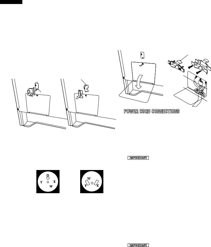
1Locate the voltage switch on the lower back side of the range.
2Remove the screw and rotate the switch plate 180 as indicated in the Figure 3.
3Reinsert the switch plate and replace screw as indicated in Figure 4. The voltage setting is indicated by the visible
marking. |
screw |
240V |
208V |
180 |
|
screw |
|
Figure 3 |
Figure 4 |
3 & 4-WIRE ELECTRICAL WALL RECEPTACLE TYPES & RECOMMENDED MOUNTING ORIENTATION ON WALL
Figure 5A illustrates 4-wire receptacle required for new and remodeled installations.
Figure 5B illustrates 3-wire receptacle that is allowed for existing installations.
4-wire wall receptacle (14-50R) |
3-wire wall receptacle (10-50R) |
Figure 5A |
Figure 5B |
ACCESS TO TERMINAL BLOCK
Loosen screw on rear access cover and pull down as illustrated in Figure 6 to access terminal block wiring connection. To close, return to original location and secure screw.
strain-relief clamp
Figure 6 |
Figure 7 |
POWER CORD CONNECTIONS
4-WIRE CONNECTION INSTRUCTIONS-FIGURE 8
Before wiring the range, review the suggested power source location. If connecting to a 4-wire electrical system for a new branch-
circuit or mobile home use a 4-wire connection.
1Follow the power supply kit manufacturer s Installation Instructions supplied with the strain relief clamp and install. See Figure 7.
2Insert the end connectors for line 1, line 2 and neutral and tighten securely to the terminal block.
IMPORTANT
 DO NOT LOOSEN the factory installed nut connections which secure the range wiring to the terminal block. Electrical failure or loss of electrical connection may occur if these 3 nuts are loosened or removed.
3You must disconnect the ground strap. Remove the factory installed ground screw and plate to release the copper ground strap from the frame of the range. Cut and discard the copper ground strap and plate. KEEP the ground screw.
4Connect the green ground wire lead with the eyelet to the frame of the range with the ground screw using the same hole in the frame where the ground screw was originally installed. See Figure 8.
5Make sure all screws are tightened securely and replace the rear access cover. See Figure 6.
3-WIRE CONNECTION INSTRUCTIONS
For existing installations ONLY, refer to Figure 9.
1Follow the power supply kit manufacturer s Installation Instructions supplied with the strain relief clamp and install. See Figure 7.
2Insert the end connectors for line 1, line 2 and neutral and tighten securely to the terminal block. See Figure 7.
IMPORTANT
 DO NOT LOOSEN the factory installed nut connections which secure the range wiring to the terminal block. Electrical failure or loss of electrical connection may occur if these 3 nuts are loosened or removed.
10
3Make sure all connections are tightened securely and replace the rear access cover. See Figure 7.
GROUNDING INSTRUCTIONSONLY 3-WIRE CONNECTIONS:
A ground strap is installed on this range which connects the center terminal of the neutral terminal block to the range chassis. The ground strap is connected to the range by the center, lowest screw See Figure 9. The ground strap must not be removed unless National State or Local Codes do not permit use of a ground strap.
Note: If the ground strap is removed for any reason, a separate ground wire must be connected to the separate ground screw attached to the range chassis and to an adequate ground source
3 & 4-WIRE PERMANENT WIRE CONNECTIONS
3–wire permanent connection – follow steps 1, 2 and 5 below. 4–wire permanent connection – follow all steps below.
Before wiring the range, review the suggested power source location drawings in Figure 2. If connecting to a 4-wire electrical system:
1Follow the manufacturer s Installation Instructions supplied with the strain relief clamp and install.
2Strip insulation away from the ends of the permanent wiring for line 1, line 2 and neutral; also strip ground wire on 4-wire
4-WIRE CONNECTION
Connect line 1 here.
Cut ground strap. Discard ground strap & ground plate.
Connect green insulated copper ground wire with ground screw here.
Figure 8
b l a c k
i t e
r e d
terminal block
Connect line 2 here.
Note: Install strain-relief clamp. Center or white wire must always be attached to the center terminal on block.
Connect neutral (white or center) here.
A user supplied strainrelief clamp must be installed at this location. It requires 1 3/8-inches (3.5 cm) diameter cord kit hole.
3-WIRE CONNECTION
|
terminal block |
|
Connect |
|
line 2 |
Connect line |
here. |
1 here. |
|
Ground strap |
|
Note: Install strain-relief clamp. Center or white wire must always be attached to the center terminal on block.
Connect neutral (white or center) here.
A user supplied strain-relief clamp must be installed at this location. It requires
1 3/8-inches (3.5 cm) diameter cord kit hole.
Figure 9
KB-3425LS/K/W
KB-4425LS/K/W
connections. Tighten all 3 or 4-wire leads to the terminal block. Follow wire locations shown in Figure 10.
IMPORTANT DO NOT LOOSEN the factory installed nut connections which secure the range wiring to the terminal block. Electrical failure or loss of electrical connection may occur if these 3 nuts are loosened or removed.
Note: For 3-wire permanent connection skip steps 3 and 4 and continue with step 5.
3Disconnect the ground strap. Remove the factory installed ground screw and plate to release the factory installed copper ground strap from frame of the range. Cut and discard the copper strap from the terminal block. KEEP the ground screw, ground plate and go to step 4.
4Connect the green ground wire lead to the frame of the range using the ground screw and plate as shown in Figure 11. Be sure to install using the same hole in the frame where the ground screw was originally installed.
5Make sure all connections are tightened securely and replace the rear access cover. See Figure 7.
Note: Non-terminated field wire compression connections must be set at approximately 90 in./lbs.
FOR 3 & 4-WIRE PERMANENT CONNECTIONS
terminal |
|
block |
|
line 1 |
line 2 |
neutral |
ground strap |
|
ground plate |
|
ground |
|
screw |
Figure 10
4-WIRE PERMANENT CONNECTION ONLY
ground
plate


 proper ground for 4-wire permanent
connection
ground
screw
ground wire lead
Figure 11
11
KB-3425LS/K/W
KB-4425LS/K/W
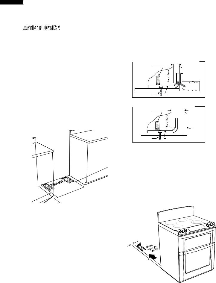
ANTI-TIP DEVICE |
2 DRILL PILOT HOLES AND FASTEN BRACKET |
||
Drill a 1/8-inch pilot hole where screws are to be located. If bracket |
|||
|
|||
NORMAL INSTALLATION STEPS |
is to be mounted to the wall, drill pilot hole at an approximate 20 |
||
degree downward angle. If bracket is to be mounted to masonry or |
|||
|
|||
ANTI-TIP BRACKET INSTALLATION INSTRUCTIONS |
ceramic floors, drill a 5/32-inch pilot hole 1 3/4-inches deep. The |
||
IMPORTANT SAFETY WARNING |
screws provided may be used in wood or concrete material. Use a |
||
To reduce the risk of tipping of the range, the range must be secured |
5/16-inch nut-driver or flat head screwdriver to secure the bracket |
||
to the floor by properly installed Anti-Tip bracket and screws packed |
in place. |
|
|
with the range. Failure to install the Anti-Tip bracket will allow the |
FASTEN BRACKET (WALL OR FLOOR MOUNTING) |
||
range to tip over if excessive weight is placed on an open door or if |
Leveling Leg |
Max 1 1/4" |
|
a child climbs upon it. Serious injury might result from spilled hot |
|
||
|
|
||
liquids or from the range itself. |
|
Wall Mount |
|
If range is ever moved to a different location, the Anti-Tip bracket |
|
|
|
must also be moved and installed with the range. Instructions are |
|
|
|
provided for installation in wood or cement fastened to either the floor |
|
Wall Plate |
|
or wall. When installed to the wall, make sure that screws completely |
|
|
|
penetrate dry wall and are secured in wood or metal. When fastening |
Floor Mount |
Anti-Tip Bracket |
|
to the floor or wall, be sure that screws do not penetrate electrical |
Figure 16 |
|
|
wiring or plumbing. |
|
||
|
FASTEN BRACKET (FLOOR MOUNTING ONLY) |
||
1 LOCATE THE BRACKET - USING THE TEMPLATE |
Leveling Leg |
More Than |
|
The bracket may be located on either the left or right side of the |
1 1/4" |
||
|
|||
range. Use the information below to locate the bracket if template |
|
|
|
is not available. |
|
|
|
|
|
Wall |
|
|
Floor Mount |
Anti-Tip Bracket |
|
Figure 15
Mark the floor or wall where left or right side of the range will be located. If rear of range is against the wall or no further than 1 1/4- inches from wall when installed, you may use the wall or floor mount method. If molding is installed and does not allow the bracket to fit push against the wall, remove molding or mount bracket to the floor. For wall mount, locate the bracket by placing the back edge of the template against the rear wall and the side edge of template on the mark made referencing the side of the range. Place bracket on top of template and mark location of the screw holes in wall. If rear of range is further than 1 1/4-inches from the wall when installed, attach bracket to the floor. For floor mount, locate the bracket by placing back edge of the template where the rear of the range will be located. Mark the location of the screw holes, shown in template.
Figure 17
3 LEVEL AND POSITION RANGE
Level range by adjusting the (4) leveling legs with a wrench. Note: A minimum clearance of 1/8-inch is required between the bottom of the range and the leveling leg to allow room for the bracket. Use a level to check your adjustments. Plug range into properly prepared electrical receptacle or if hard wired, check that it was completed properly. Check door condition for evenness and stability. Slide range back into position.
Visually check that rear leveling leg is inserted into and fully secured by the Anti-Tip bracket by looking underneath the range with a flashlight and carefully attempt to tilt it forward.
1 5/8" to edge of bracket
Range Slide 
Figure 18
KB-3425L Shown
12
KB-3425LS/K/W
KB-4425LS/K/W
KB-3425LS
13

KB-3425LS/K/W KB-4425LS/K/W
Schematic-Off Condition
|
|
N |
|
|
|
|
|
|
|
|
|
|
|
|
|
|
|
|
|
|
|
COOK TOP |
|
|
|
|
|
|
|
|
|
|
|
|
|
|
|
|
|
|
|||||
|
|
WHT |
|
|
|
|
|
|
|
|
|
|
|
|
|
|
|
|
|
|
|
|
|
|
|
|
|
|
|
|
|
|
|
|
|
|
|
|
|
||||||
|
|
|
|
|
|
|
|
|
|
|
|
|
|
|
|
|
|
|
|
|
|
|
|
|
|
|
|
|
|
|
|
|
|
|
|
|
|
|
|
|
|
|
|
|
|
viewback sockets lamp on side right the on located is that Terminal 2. .wire neutral to connected be must |
NOTES: .notice without change to subject are colors wire / Circuits 1. |
WHT |
|
HOT |
|
|
|
|
|
|
|
|
|
|
|
|
|
|
|
|
|
|
|
|
|
|
|
|
|
|
|
|
|
|
|
|
|
|
|
|
|
|
BLK |
|
|
LIGHT |
|
|
|
|
|
|
|
|
|
|
|
|
|
|
|
|
|
|
|
|
|
|
|
|
|
|
|
|
|
|
|
|
|
|
|
|
|
|
BLK |
BLK |
|
||||
SWITCHES |
|
|
|
|
|
|
|
|
|
|
|
|
|
|
|
|
|
|
|
|
|
|
|
|
|
|
|
|
|
|
|
|
|
|
|
|
|
|
|
|
|||||
|
|
|
|
|
|
|
|
|
|
|
BLK |
|
|
|
|
BLK |
|
|
|
|
|
|
|
|
|
|
|
|
|
|
ORG |
|
|
|
|
|
|
|
BLK |
|
|
||||
|
BLK |
BLK |
BLK |
|
|
|
|
|
|
|
|
|
|
|
|
|
|
|
|
|
|
|
|
|
|
|
|
|
|
|
|
|
|
YLW |
|
|
|
||||||||
S |
S |
S |
S |
|
|
|
|
|
|
L1 |
|
|
|
|
|
L1 |
|
|
|
|
|
|
|
|
|
|
|
|
|
L1 |
|
|
|
|
|
|
|
|
|||||||
|
|
|
|
|
|
|
|
|
|
P2 |
|
|
|
|
|
|
|
|
|
|
|
|
|
|
|
|
|
|
|
|
|
||||||||||||||
/2b |
|
/2b |
/2b |
/2b |
|
|
CONTROL |
|
|
|
P2 |
|
CONTROL |
|
|
|
/ |
|
|
|
|
|
|
|
|
|
|
|
|
|
P2 |
|
|
|
|
|
|
|
|
|
|||||
H |
H |
H |
H |
|
|
4 |
|
/ |
|
4 |
|
P |
|
|
|
|
|
|
|
|
|
|
|
4 |
/ |
|
|
|
|
|
|
|
|
|
|||||||||||
1b/ YLW BLU |
1b/ BLK |
1b/ BLU |
1b/ BRN |
|
|
WHT |
|
BLK /H1 |
YLW |
BLK |
/H1 |
|
YLW |
|
|
|
|
|
|
|
|
CONTROL |
|
WHT |
/H1 |
|
YLW |
WHTYLW |
BLKP24a |
|
RED 4 |
|
CONTROL S2S1 |
|
|
||||||||||
|
|
|
YLW |
|
|
|
|
|
|
|
|
YLW |
|
|
YLW |
|
|
|
|
||||||||||||||||||||||||||
|
|
|
P |
|
|
|
|
|
|
|
|
|
|
|
|
|
|
|
|
||||||||||||||||||||||||||
LF YLW YLW SURFACE |
BLK YLWBLU |
BLU YLWBLU LR |
RR BRN YLWBLU RF |
|
|
|
|
|
|
|
|
|
|
ORG |
|
|
|
|
|
|
|
|
|
|
|
|
|
|
|
P |
|
P1A 4A |
|
P1B 4 |
YLW RED |
YLW |
|
|
|
L1 |
|||||
|
|
|
|
|
|
|
|
|
|
|
|
|
|
|
|
|
|
YLW |
|
|
|
|
|
|
|
/ |
OUTSIDE |
/ |
|
|
|
|
|||||||||||||
|
|
|
|
|
|
YLW |
|
|
|
|
|
|
|
|
|
4 WHT |
|
|
|
WHT |
|
ELEMENT |
RIGHT |
INSIDE |
|
YLW |
|
|
|||||||||||||||||
|
|
|
|
|
|
|
|
|
|
|
|
|
|
|
|
|
|
|
|
|
|
|
|||||||||||||||||||||||
|
|
|
WHT |
|
|
|
|
|
|
YLW |
|
|
|
|
|
|
|
|
|
|
|
|
|
|
|||||||||||||||||||||
YLW |
|
|
|
|
|
LEFT |
4 BLK |
|
|
|
|
|
|
ELEMENT |
RIGHT |
|
4 |
|
|
|
|||||||||||||||||||||||||
|
|
|
4 |
|
|
|
|
|
|
|
|
|
|
|
|
|
|||||||||||||||||||||||||||||
|
|
|
/P1 |
|
|
|
|
|
|
|
|
|
|
|
|
||||||||||||||||||||||||||||||
|
|
YLW |
|
ELEMENT |
SURFACE ELEMENT LEFT |
|
P1/ |
|
|
ELEMENT |
WARMER |
|
SURFACE |
|
|
|
P1/ |
|
|
|
|||||||||||||||||||||||||
|
|
2 |
|
SURFACE |
YLW FRONT |
2 |
|
|
|
P1/ |
|
REAR |
|
2 |
|
SURFACE |
|
|
|
||||||||||||||||||||||||||
LIGHTSURFACEHOT |
PROTECTOR |
1a |
|
|
|
REAR |
PROTECTOR |
1a |
|
|
|
|
PROTECTORSURFACE |
2a 1a |
2 |
PROTECTOR |
2a YLW1a |
|
|
|
|
FRONT |
PROTECTOR |
2a 1a |
|
|
|
|
|||||||||||||||||
2a |
|
|
|
2a |
|
LIGHT INDICATOR |
|
YLW |
|
|
BRN |
LIGHT INDICATOR |
|
||||||||||||||||||||||||||||||||
BRN |
2 |
|
WHT |
2 |
|
|
2 |
|
|
|
|||||||||||||||||||||||||||||||||||
|
H2/ |
|
/ H2 |
|
|
|
H2/ |
|
2 |
|
|||||||||||||||||||||||||||||||||||
|
|
|
|
|
|
|
|
|
|
|
|
|
L2 |
|
|
|
|
L2 |
|
|
|
|
|
|
|
|
YLW |
|
|
|
|
|
|
L2 |
|
|
|
|
|
|
|
|
|
|
|
|
|
|
|
|
|
|
|
|
|
|
|
P1 |
|
|
|
|
P1 |
|
RED |
|
|
|
|
|
|
|
|
|
|
|
P1 |
|
|
RED WHT |
|
P1 |
|
|
RED |
|
|
||||
|
|
|
|
|
|
|
|
|
|
|
RED |
|
/ |
|
|
|
/ RED RED |
|
|
|
|
|
|
|
|
|
RED |
|
|
|
/ |
|
|
RED |
RED RED |
RED |
|
||||||||
|
|
|
|
|
|
|
|
|
|
|
|
|
|
|
|
|
|
|
|
|
|
|
|
|
|
|
|
|
RED |
|
|||||||||||||||
|
|
|
|
|
|
|
|
|
WHT |
|
|
|
|
|
|
|
|
|
|
|
|
|
|
|
|
|
|
|
|
|
|
|
|
|
|
|
|
|
|
|
|
|
RED |
|
L2 |
|
|
|
|
|
|
|
|
|
|
|
|
|
|
|
|
|
|
|
|
|
|
|
|
|
|
|
|
|
|
|
|
|
|
|
|
|
|
|
|
|
|
|
|
|
|
|
|
|
|
|
|
|
|
|
|
|
|
|
|
|
|
|
|
|
|
|
|
|
|
|
|
|
|
|
|
|
|
|
|
|
|
|
|
|
|
|
|
|
|
RED |
L2 |
|
|
|
|
|
|
|
|
|
|
|
|
|
|
|
|
|
|
|
|
|
|
|
|
|
|
|
|
|
|
|
|
|
|
|
|
|
|
|
|
|
|
|
|
|
|
|
|
|
|
|
|
|
|
|
|
|
|
|
|
|
L2 |
|
|
|
|
|
|
|
|
|
|
|
|
|
|
|
|
|
|
|
|
|
|
|
|
|
|
|
RED |
|
|
|
|
|
|
|
|
|
|
|
WHT |
|
|
|
|
|
|
|
|
|
|
|
|
|
|
|
|
|
|
|
|
|
|
|
|
|
|
|
|
|
|
|
|
|
|
|
|
|
|
|
|
|
|
|
|
|
|
|
|
|
|
|
|
|
|
|
|
|
|
|
|
|
|
|
N |
|
|
|
|
|
|
|
|
|
|
|
|
|
|
|
|
|
|
|
|
|
|
|
|
BLK |
|
|
|
|
|
|
|
|
|
|
|
|
|
|
|
|
|
|
|
|
|
|
|
|
|
|
|
|
|
|
|
|
|
|
|
|
|
BLK |
|
|
|
|
|
L1 |
|
BLK |
|
|
|
|
|
|
|
|
|
|
|
|
|
|
|
|
|
|
|
|
|
|
|
|
|
|
|
|
|
|
|
|
|
|
|
|
|
BLK |
L1 |
|
|
|
|
|
|
|
|
|
|
|
|
|
|
|
|
|
|
|
|
|
|
|
|
|
|
|
|
|
|
|
|
|
|
|
|
|
|
|
|
|
|
|
|
||
|
|
|
|
|
|
|
|
|
|
|
|
|
|
|
RED |
|
|
|
|
|
|
|
|
|
|
|
|
|
|
|
|
|
|
|
|
|
|
|
|
|
|
|
|
|
|
|
|
|
L |
|
|
|
|
|
|
|
|
|
|
L |
|
|
|
|
|
|
|
|
|
|
|
|
|
|
|
|
|
|
|
|
|
|
|
|
|
|
|
|
|
||
|
|
|
|
|
|
|
|
|
|
|
|
|
FUSE |
|
|
|
|
|
BLK |
WHT |
|
|
|
|
RED |
|
|
|
|
|
|
|
|
|
|
|
|
|
|
|
BLK |
|
|||
|
|
|
|
|
|
|
|
|
|
|
|
|
|
|
|
|
|
|
|
|
|
|
|
|
|
|
|
|
|
|
|
|
|
|
|
|
|
|
|
|
|
|
|||
|
|
|
|
|
|
|
|
|
|
|
|
|
20A |
|
|
|
|
|
|
|
|
|
|
|
|
|
|
|
|
|
|
|
|
|
|
|
|
|
|
|
|
|
|
|
|
|
|
|
|
|
|
RESISTOR 470 kohm 1/2W |
|
|
|
|
|
|
|
|
|
|
|
3 |
1 |
|
|
|
WHT |
|
|
|
|
|
|
|
|
|
|
|
|
|
|
|
|
|
|
||||
|
|
|
|
|
|
|
|
|
|
|
|
|
|
|
|
|
|
|
|
|
|
|
|
|
|
|
|
|
|
|
BLK |
|
|
|
|
|
|
|
|
|
|
||||
|
|
|
|
LINE CROSS CAPACITOR 1.0uF 250V |
|
|
|
|
|
|
|
|
|
|
|
SUPPLY POWER SWITCHING |
|
|
|
|
|
DOOR |
|
|
|
|
M4 |
|
|
|
|
|
|
|
|
|
|||||||||
|
|
|
|
|
|
|
|
|
|
|
|
|
|
|
|
|
|
|
|
|
|
|
|
|
|
|
|
|
|
|
|
|
|
||||||||||||
|
|
|
|
|
|
|
|
|
|
|
|
|
|
|
|
|
|
|
|
|
|
|
|
|
|
SWITCH |
|
|
|
RED |
M5 |
|
|
|
|
|
|
|
|
|
|||||
|
|
|
|
|
|
|
|
|
|
|
|
|
|
|
|
|
|
|
|
|
|
|
|
|
|
|
|
|
|
|
|
|
|
|
|
|
|
|
|
|
|||||
|
|
|
|
|
|
NOISE SUPRESSION COIL |
|
|
|
|
|
|
|
|
|
|
|
|
|
|
|
|
|
|
|
|
|
|
|
|
|
|
|
|
|
|
|
|
|||||||
|
|
|
|
|
|
|
|
|
|
|
|
|
|
|
|
|
|
|
|
|
|
|
|
|
|
|
|
|
RED |
M9 |
|
|
|
UNIT CONTROL |
|
|
|
|
|
||||||
|
|
|
|
|
|
|
|
|
|
|
|
|
|
|
|
|
|
|
|
|
|
|
|
|
|
DOOR LOCK |
|
|
|
|
|
|
|
|
|
|
|||||||||
|
|
|
|
|
|
|
|
|
|
|
|
|
|
|
|
|
|
|
|
|
|
|
|
|
|
|
YLW |
|
|
|
|
|
|
|
|
|
|||||||||
|
|
|
|
|
|
|
|
|
|
|
|
|
|
|
|
|
|
|
|
|
|
|
|
|
|
MOTOR |
|
|
|
|
M10 |
|
|
|
|
|
|
|
|||||||
|
|
|
|
|
|
|
|
|
|
|
|
|
|
|
|
|
|
|
|
|
|
|
|
|
|
|
|
|
|
|
|
|
|
|
|
|
|
||||||||
|
|
|
|
|
|
|
|
|
|
|
|
|
|
|
|
|
|
|
|
|
|
|
|
|
|
SWITCH |
|
|
|
BRN |
M8 |
|
|
|
|
|
|
|
|
||||||
|
|
|
|
LINE BYPASS CAPACITOR |
|
LINE BYPASS CAPACITOR |
|
|
|
|
|
|
|
|
|
|
|
|
|
|
|
|
|
|
|
|
|
|
|
|
|
|
|
||||||||||||
|
|
|
|
|
|
|
|
|
|
|
|
|
|
|
|
|
|
|
|
|
|
|
ORG |
|
|
|
|
|
|
|
|
|
|||||||||||||
|
MICROWAVE |
|
|
0.0033uF 250V |
|
|
|
0.0033uF 250V |
|
|
|
|
|
|
|
|
|
|
|
|
|
|
|
|
|
|
|
|
|
|
M11 |
|
|
|
|
|
OVEN |
||||||||
|
|
|
|
|
|
|
|
|
|
|
|
|
|
|
|
|
|
|
|
|
|
|
|
|
|
|
|
|
|
|
|
|
|
||||||||||||
|
|
|
|
|
|
|
|
|
|
|
|
|
|
|
|
|
|
|
|
UNIT |
|
|
|
|
|
THERMISTOR |
|
|
|
|
|
|
|
|
|||||||||||
|
|
|
|
|
|
|
|
|
|
|
|
|
|
|
|
|
|
|
|
|
|
|
|
|
|
|
M12 RY6 |
|
|
|
|
|
|||||||||||||
|
|
|
|
|
|
|
|
|
|
|
|
|
|
|
|
|
|
|
|
|
|
|
|
|
|
|
|
|
|
|
ORG |
|
|
|
|
|
|||||||||
|
|
|
|
|
|
|
|
|
|
|
|
|
|
|
|
|
|
|
|
|
|
|
|
|
|
|
|
|
|
|
|
|
|
|
|
|
|
|
|
|
|||||
|
|
|
|
|
|
|
|
|
|
|
|
|
|
RED |
|
|
|
|
|
|
|
|
|
|
|
WHT |
|
|
|
|
FM |
YLW |
|
|
|
|
|
|
|
|
|||||
|
|
|
|
|
|
|
|
|
|
|
|
|
|
|
|
|
|
|
|
|
|
|
|
|
WHT |
|
|
|
|
D1 C3 |
|
|
|
|
|
|
|
||||||||
|
|
|
|
|
|
|
|
|
|
|
|
|
|
|
OVEN THERMAL -CUT OUT-CUT |
|
1 |
3 |
|
|
|
|
|
|
|
CLOSS FLOW |
|
|
|
|
|
|
|
|
|||||||||||
|
|
|
|
|
DOOR |
|
|
|
|
|
|
|
|
|
|
|
|
|
|
|
|
|
FAN MOTOR |
|
RY9 |
|
|
|
|
|
|||||||||||||||
|
|
|
|
|
SENSING |
|
|
|
|
|
|
|
|
|
|
|
|
|
|
|
|
|
|
|
|
|
|
|
BLK |
|
|
|
|
|
|||||||||||
|
|
|
|
|
|
|
|
|
|
|
|
|
|
|
|
|
|
|
|
|
|
|
|
|
|
|
|
|
|
|
|
|
|
|
|||||||||||
|
|
|
|
|
SWITCH |
|
|
|
|
|
|
|
|
|
|
|
|
|
|
|
|
|
|
|
|
|
|
|
|
|
|
|
|
|
|
||||||||||
|
|
|
|
|
M1 |
|
|
|
|
|
|
|
|
|
|
|
|
|
|
|
|
|
|
|
|
|
|
|
|
|
|
|
|
|
|
||||||||||
|
|
|
|
|
|
WHT |
|
|
|
|
|
|
|
|
|
|
|
|
|
|
|
|
|
|
|
|
|
|
|
|
|
|
|
|
|
|
|||||||||
|
|
|
|
|
|
|
M3 |
|
|
|
|
|
|
|
|
|
|
|
|
|
|
|
RED |
|
CM |
|
|
|
|
|
|
|
|
|
|||||||||||
|
|
|
|
|
GRN |
|
|
|
|
|
|
|
|
|
|
|
|
|
|
|
|
|
|
|
|
|
|
|
|
|
|
|
|
|
|
||||||||||
|
|
|
|
|
|
|
|
|
|
|
|
|
|
|
|
|
DOOR |
|
|
RED |
|
|
|
|
|
|
|
|
|
|
|
|
|
||||||||||||
|
|
|
|
|
|
|
|
|
|
|
|
|
|
|
|
|
|
|
|
|
|
|
|
|
|
|
|
|
|
|
|
|
|
||||||||||||
|
|
|
|
|
|
|
|
|
|
|
|
|
|
|
|
|
|
MOTOR |
|
|
|
|
BLU |
|
|
|
|
|
|
|
|
|
|
|
|
||||||||||
|
|
|
|
|
|
|
|
|
|
|
|
|
|
ORG |
BLK |
RED |
|
|
MICROWAVE OPEN |
|
|
|
|
CONV. MOTOR |
RY8 |
|
|
|
|
|
|||||||||||||||
|
|
|
|
|
|
|
|
|
|
|
|
|
|
|
|
|
|
|
|
DOOR LOCK |
|
|
|
|
|
|
|||||||||||||||||||
|
|
|
HUMIDITY |
|
|
|
|
|
|
|
|
|
|
|
|
|
|
|
|
|
|
|
|
|
|
|
|||||||||||||||||||
|
DRAWER |
|
|
|
|
|
|
|
|
|
|
|
|
OUT |
|
|
E1 |
|
E2 |
|
|
CLOSE- |
|
|
|
|
|
|
|
|
|
|
|
|
|
|
|
||||||||
|
|
|
SENSOR |
|
F3 |
|
|
|
|
|
|
|
|
|
|
|
|
|
|
|
WHT |
|
MOTOR |
|
BRN |
|
|
|
|
|
|
|
|
|
|
||||||||||
|
|
|
|
|
|
|
|
|
|
|
|
|
|
|
|
|
|
|
|
|
|
|
|
|
LM |
|
|
|
|
|
|
|
|
|
|
||||||||||
|
|
|
|
|
|
|
|
|
|
|
|
|
|
|
|
|
|
|
|
|
|
|
|
|
|
|
|
|
|
|
|
|
|
|
|
||||||||||
|
|
|
|
|
|
F2 |
|
|
|
|
|
|
|
COM. |
|
|
|
|
|
|
|
|
|
|
|
WHT |
|
|
|
|
|
|
|
|
|
|
|
|
|
|
|
|
|
||
|
|
|
|
|
|
|
|
|
|
|
|
|
|
|
|
|
|
|
N1 |
RED |
|
|
|
|
|
|
|
|
|
|
|
|
|
|
RY7 |
|
|
|
|
|
|
|
|||
|
|
|
RED |
|
|
|
|
|
|
|
|
|
|
|
|
|
|
|
|
|
|
|
|
|
|
|
|
|
|
|
|
|
|
|
|
|
|
|
|
|
|
|
|
||
|
|
|
|
|
|
|
|
|
|
|
|
|
|
|
|
|
|
|
|
BLK |
|
|
|
|
|
|
|
OVEN LAMP |
|
|
|
|
|
|
|
|
|
|
|
||||||
|
|
|
|
|
|
F1 |
|
RY5 |
|
|
|
|
|
|
|
|
RY11 |
|
N2 |
|
|
|
|
|
WHT |
|
|
|
|
OL |
ORG |
|
|
|
|
|
|
|
|
|
|
||||
|
|
|
|
|
|
|
|
|
|
|
|
|
|
|
|
|
|
|
|
|
|
|
|
|
|
|
|
|
|
|
|
|
|
|
|
||||||||||
|
|
|
|
|
|
|
|
|
|
|
|
|
|
|
|
|
|
|
|
|
|
|
|
|
WHT |
|
|
|
|
|
|
|
|
|
|
|
|
|
|
|
|
|
|||
|
WHT |
BRNBLK SWITCHINTELOCKSECONDARY |
|
FM |
|
BLK |
C1 |
|
CONTROLUNIT |
|
|
|
ORG |
|
MG THERMAL |
|
|
N3 |
ORG |
DM |
|
DRAWER |
|
|
|
|
|
|
|
|
|
|
D3 C7C5 |
RY10 |
|
|
|
|
RED |
|
|
||||
|
|
|
|
|
|
|
|
|
|
|
|
|
|
|
|
|
|
|
|
|
|
|
|
|
|
|
|
|
|
||||||||||||||||
|
FAN MOTOR |
|
RY1 |
|
|
|
|
|
|
N4 |
YLW |
|
|
|
|
|
|
|
|
|
|
|
|
|
|
|
|
|
|
|
|||||||||||||||
|
|
|
|
|
|
|
|
|
|
|
|
|
|
|
|
|
|
|
|
|
|
|
|
|
|
|
|
||||||||||||||||||
|
BRNREDBLK |
|
ORG |
ORG |
|
|
|
|
|
|
|
|
|
|
|
|
|
|
YLW |
|
|
|
|
|
|
|
|
|
|
||||||||||||||||
|
|
|
|
WHT |
SM |
|
|
|
|
|
|
|
|
|
|
|
|
|
|
|
|
|
|
|
|
|
|
|
|
|
|
|
|
|
D5 |
|
|
|
|||||||
|
|
|
|
WHT |
ORG |
RED |
.O.N |
|
|
|
|
|
|
|
|
|
|
|
|
N5 |
BLU |
|
|
|
|
|
|
|
WHT |
|
WHT |
|
|
|
|
|
|
|
|
||||||
|
|
|
|
|
|
|
|
|
|
|
|
|
|
|
|
|
|
|
|
|
C-RY |
|
|
|
|
|
|
|
|
|
|
|
|||||||||||||
|
|
|
|
STIRRER MOTOR |
|
RY2 |
PRIMARY INTERLOCK |
|
|
|
|
|
|
|
|
|
|
|
|
|
E6 |
|
|
|
|
|
|
|
|||||||||||||||||
|
|
|
|
|
|
|
|
|
|
|
|
|
|
|
|
|
|
WHT |
|
|
|
|
|
|
|
|
|
||||||||||||||||||
|
|
|
|
WHT |
OL |
ORG |
RED |
|
|
|
|
RELAY |
|
|
|
|
|
|
|
|
|
|
|
|
|
|
|
|
|
GRY |
|
|
|
|
|
|
|
|
|||||||
|
|
|
|
.COM |
|
|
|
|
|
|
|
|
|
|
|
|
|
|
|
FRONT |
|
DOOR |
|
|
|
|
|
|
|
E5 E3 |
|
|
|
|
|
|
|
|
|
||||||
|
|
|
|
WHT |
|
|
|
|
|
|
|
|
|
|
|
|
|
|
M6 |
|
GRY |
|
BLK |
|
|
|
|
BLK |
|
|
|
|
|
|
|
|
|
|
|||||||
|
|
|
|
|
|
|
|
|
|
|
|
|
|
|
|
|
|
|
|
|
|
|
|
|
|
|
|
|
|
|
|
|
|
|
|||||||||||
|
|
|
|
OVEN LAMP |
|
|
|
|
|
|
|
N.O. |
|
|
|
|
|
|
|
|
|
|
|
|
|
|
|
|
|
|
|
|
|||||||||||||
|
|
|
|
|
|
|
|
|
|
|
|
|
|
|
M7 |
|
|
|
CONV. HEATER |
BLK |
|
|
|
|
|
|
|
|
|
|
|||||||||||||||
|
|
|
|
|
|
|
|
|
|
|
|
|
|
|
|
|
|
|
|
|
|
SWITCH |
|
|
|
|
|
|
|
|
|
|
|
|
|||||||||||
|
|
|
|
|
|
|
|
|
|
|
|
|
|
RED RED |
|
|
|
|
|
BRN |
|
|
POSITION |
ORG B-RY |
|
|
|
|
|
|
WHT |
|
RY3 |
|
|
|
|
|
|
|
|||||
|
|
|
|
|
|
|
|
|
|
|
|
|
|
|
|
|
|
|
|
|
|
|
|
|
|
|
|
|
|
|
|
|
|
|
|
|
|
||||||||
|
|
|
|
|
|
BRN |
|
|
RED |
|
|
|
|
|
|
|
|
|
|
|
|
|
|
|
|
|
|
|
|
|
|
|
|
|
|
|
|
||||||||
|
|
|
|
|
|
|
|
|
|
|
|
|
|
|
|
|
|
M14 |
|
BLK |
REAR |
|
|
|
|
|
|
BLU |
|
|
|
|
|
|
|
COM. |
|
|
|
||||||
|
|
|
|
|
|
|
|
|
MONITOR SWITCH |
|
|
|
|
|
|
|
|
|
|
|
|
|
RED |
|
|
|
|
|
|
|
|
|
|
|
|
||||||||||
|
|
|
|
|
|
|
|
|
|
|
RED |
|
|
|
|
|
M13 |
|
|
SWITCH |
DOOR |
BOTTOM HEATER |
|
BLK |
BLK |
N.O. |
|
|
|
|
|
|
BLK |
|
|
||||||||||
|
|
|
|
|
|
|
|
|
|
|
|
|
|
|
|
|
|
|
|
BLK |
|
|
POSITION |
|
|
|
|
|
|
|
|
|
|
|
|
|
|
||||||||
|
|
|
|
RED |
|
|
|
|
POWER TRANSFORMER |
|
|
|
|
|
|
|
|
|
|
|
|
|
|
|
|
|
|
|
|
BLK |
|
|
|
|
|
|
|
|
|
|
|
||||
|
|
|
|
|
|
|
|
|
|
|
|
|
|
|
|
|
|
BLK |
|
|
|
|
TOP HEATER |
|
|
|
BLK |
|
|
|
|
|
|
|
|
|
|
|
|||||||
|
|
|
|
BLK |
|
|
|
|
|
|
|
|
|
|
|
|
|
|
|
|
|
|
|
LOW |
|
|
|
|
|
|
|
|
|
|
|
|
|
|
|||||||
|
|
|
|
|
|
|
|
|
|
|
|
|
|
|
|
|
|
|
|
|
|
|
|
|
|
|
|
|
|
|
|
|
|
|
|
|
|
||||||||
|
|
|
VOLTAGESWITCH |
BRN |
|
|
|
|
|
|
|
|
|
|
|
|
|
|
|
|
A1 A4A6 |
WHT |
|
|
|
|
|
RED |
|
|
|
|
|
|
|
|
|
|
|
||||||
|
|
|
|
|
|
|
|
|
|
|
|
|
|
|
|
|
|
|
|
VOLTAGE |
|
|
|
|
|
|
|
|
|
|
|
|
|
|
|
||||||||||
|
|
|
|
|
|
|
|
|
|
|
|
|
|
|
|
|
|
|
|
|
|
|
|
|
|
COM. |
|
|
|
|
|
|
|
|
|
|
|||||||||
|
|
|
|
|
|
|
|
|
|
|
|
|
|
|
|
|
|
|
|
|
|
|
|
|
|
|
|
|
RY4 |
|
|
|
|
|
|
|
|||||||||
|
|
|
|
|
|
|
|
|
|
|
|
|
|
|
|
|
|
|
|
|
|
|
|
|
|
|
|
|
|
|
|
|
|
|
|
|
|
||||||||
|
|
|
|
|
|
|
|
|
|
|
|
|
|
|
|
|
|
|
BLU |
|
|
|
|
|
|
|
|
|
|
|
|
|
|
|
|
|
|
|
|
||||||
|
|
|
|
|
|
|
|
|
|
|
|
|
|
|
|
|
|
|
|
|
|
TRANSFORMER |
|
|
|
|
|
|
|
|
N.O. |
|
|
|
|
|
|
|
|
|
|
||||
|
|
|
|
|
|
|
|
|
|
|
|
|
|
|
|
|
|
|
|
|
A2 |
|
YLW |
|
|
|
|
|
|
|
|
|
|
|
|
|
|
|
|
|
|
|
|||
|
|
|
|
|
|
|
|
|
|
|
|
|
|
|
|
|
|
|
|
|
|
|
|
|
|
|
|
BRN |
|
|
|
|
|
|
|
|
|
|
|
|
|||||
|
|
|
|
|
|
|
|
|
|
|
|
|
|
|
|
|
|
|
|
|
|
|
|
|
|
|
|
|
|
|
|
|
|
|
|
|
|
|
|
|
|
||||
|
|
|
|
|
|
|
|
|
|
|
|
|
|
|
|
|
|
|
|
|
|
|
|
|
|
|
|
|
|
|
|
|
|
|
|
|
|
|
|
|
|
|
|||
|
|
|
|
CAPACITOR |
|
|
|
|
|
|
|
|
|
|
|
|
|
|
|
|
|
|
|
|
|
|
|
|
|
|
|
|
|
|
|
|
|
|
|
|
|
|
|
|
|
|
|
|
|
1.00uF |
|
|
|
|
|
|
|
|
|
|
|
|
|
|
|
|
|
|
|
|
|
|
|
|
|
|
|
|
|
|
|
|
|
|
|
|
|
|
|
|
|
|
|
|
|
AC 2300V |
|
|
|
|
|
|
|
|
|
|
|
|
|
|
|
|
|
|
|
|
|
|
|
|
|
|
|
|
|
|
|
|
|
|
|
|
|
|
|
|
|
|
|
|
|
RECTIFIER |
|
|
MAGNETRON |
|
|
|
|
|
|
|
|
B1 |
|
|
B3 |
|
|
|
|
|
|
|
|
|
|
|
|
|
|
|
|
|
|
|
|
|
|
|
|
||
|
|
|
|
|
|
|
|
|
|
|
|
|
|
|
|
|
|
|
|
|
|
|
|
|
RED |
|
|
|
|
|
|
|
|
RED |
|
|
|
|
|
|
|
|
|
||
|
|
|
|
|
|
|
|
|
|
|
|
|
|
|
|
|
|
|
|
|
|
|
|
|
|
|
|
|
|
|
|
|
|
|
|
|
|
|
|
|
|
|
|
||
WHT |
OVEN THERMAL |
|
|
|
CUT-OUT (THERMAL OVEN) |
14
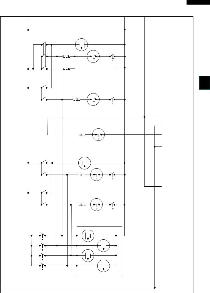
COOK TOP SCHEMATIC (DETAIL)
KB-3425LS/K/W KB-4425LS/K/W
|
|
L1 |
|
|
|
|
|
|
|
|
|
|
|
|
L2 |
L2 |
|
|
BLK |
|
|
|
|
|
|
|
|
|
|
|
|
|
RED |
RED |
RED |
|
BLK BLK |
BLK |
CONTROL |
|
|
|
|
|
|
|
|
|
|
RED RED RED |
|
|
|
|
|
|
|
|
|
|
|
|
|
|
INDICATOR LIGHT |
|
|
|
|||
|
|
YLW S1 |
S2 |
|
|
YLW |
|
|
|
RED |
|
|
|||||
|
|
|
|
YLW |
|
|
|
|
|
|
|
|
|
RED |
|
|
|
|
|
|
|
4 |
|
|
YLW |
|
|
|
|
|
|
2 |
P1 |
|
|
|
|
|
|
|
RED RED |
|
|
|
|
|
BRN |
|
|
||||
|
|
|
|
|
|
|
P1B / |
INSIDE |
1a |
|
2a |
|
RED |
|
|
||
|
|
|
|
|
|
|
4 |
|
|
PROTECTOR |
|
|
|
|
|||
|
|
BLK P2 |
4a |
|
OUTSIDE |
|
|
|
RED |
|
|
||||||
|
|
WHT P1A / |
|
|
|
|
|
|
|
WHT |
|
|
|||||
|
|
YLW |
|
|
RIGHT FRONT |
|
|
|
|
|
|
||||||
|
|
|
|
|
|
|
|
|
|
|
|||||||
|
|
|
|
|
|
|
4A |
|
|
|
|
|
|
|
|||
|
|
|
|
YLW |
YLW |
|
SURFACE |
|
|
|
|
|
|
|
|
||
|
|
|
L1 / |
|
ELEMENT |
|
|
|
|
|
|
|
|
||||
|
|
|
|
|
|
|
|
|
|
|
|
|
|
|
|
|
|
|
|
ORG |
P2 |
P |
|
|
|
|
|
|
|
|
|
|
|
|
|
|
|
|
|
H1 / |
|
|
|
P1 / |
2 |
|
|
|
H2 / |
L2 / |
|
|
|
|
|
|
|
4 |
|
WHT |
|
WHT |
4 |
|
|
YLW |
2 |
P1 |
|
|
|
|
|
|
CONTROL |
|
|
|
YLW |
RIGHT REAR 1a |
|
2a |
|
RED |
|
|
|||
|
|
|
|
|
|
|
|
|
|
|
|
||||||
|
|
|
|
|
|
|
|
|
SURFACE |
|
PROTECTOR |
|
|
|
|
||
|
|
|
|
|
|
YLW |
YLW |
ELEMENT |
|
|
|
|
|
|
|
||
|
|
|
|
|
|
|
|
|
|
|
|
|
|
|
|||
TOP |
|
|
|
|
|
|
|
|
|
|
|
|
|
|
|
|
N |
|
|
|
|
|
|
|
|
P1 / |
|
2 |
|
|
|
|
|
||
|
|
|
|
|
|
|
WHT |
4 |
|
|
|
YLW |
|
|
|||
|
|
|
|
|
|
|
|
|
|
|
1a |
2a |
|
|
|
||
COOK |
|
|
|
|
|
|
|
|
|
WARMER |
|
|
|
||||
|
|
|
|
|
|
|
|
|
SURFACE |
|
PROTECTOR |
|
|
|
|
||
|
|
|
|
|
|
|
|
|
ELEMENT |
|
|
|
|
|
|
||
|
|
|
|
|
|
|
|
|
|
|
|
|
|
|
|
|
|
|
|
|
L1 / |
|
|
|
|
|
|
|
|
|
INDICATOR LIGHT |
|
|
|
|
|
|
BLK |
P2 |
P YLW |
|
|
YLW |
|
|
|
RED |
|
|
||||
|
|
ORG |
|
|
|
|
|
|
|
|
|
|
|
|
|
|
|
|
|
|
|
H1 / |
|
|
|
|
P1 / |
2 |
|
H2 / |
L2 / |
|
|
||
|
|
|
|
4 |
|
|
|
|
BLK |
4 |
|
2 |
P1 RED |
|
|
||
|
|
|
CONTROLBLK |
YLW |
|
|
YLW |
LEFT FRONT1a |
2aWHT |
RED |
|
|
|||||
|
|
|
L1 / |
YLW |
|
YLW |
|
SURFACE |
|
PROTECTOR |
|
|
|
L2 |
|||
|
|
|
|
|
|
|
|
|
ELEMENT |
|
|
|
|
|
|
|
|
|
|
BLK |
P2 |
P |
|
|
|
|
|
LEFT REAR |
|
|
|
|
|
||
|
|
BLK |
|
|
|
|
|
|
|
SURFACE |
|
|
|
|
|
|
|
|
|
|
|
H1 / |
|
|
|
|
ELEMENT |
|
|
|
H2 / |
L2 / |
|
|
|
|
|
|
|
|
|
|
|
P1 / |
|
|
|
|
|
||||
|
|
|
|
4 |
|
|
|
|
|
2 |
|
2 |
P1 |
|
|
||
|
|
|
|
WHT |
|
|
WHT |
4 |
|
|
|
||||||
|
|
|
CONTROL |
|
|
YLW |
|
1a |
2a BRN |
RED |
|
|
|||||
|
|
|
|
|
|
|
|
|
YLW |
|
|
PROTECTOR |
|
|
|
|
|
|
|
|
|
|
|
|
|
|
HOT SURFACE LIGHT |
|
WHT |
|
WHT |
||||
|
|
|
|
|
|
|
|
|
|
|
|
|
|
||||
|
|
2b / |
1b / |
|
|
|
|
|
|
|
|
RR |
|
|
|
|
|
|
|
BLK |
S |
H |
BRN |
|
|
|
|
|
|
|
|
|
|
||
|
|
BLU |
|
|
YLW |
|
|
BRN |
|
|
|
|
|
|
|
||
|
|
2b / |
1b / |
|
|
|
|
|
|
|
|
|
RF |
|
|
|
|
|
|
BLK |
S |
H |
BLU |
|
|
BLU |
|
|
|
|
|
|
|||
|
|
BLU |
|
|
YLW |
|
|
|
|
|
|
|
|
|
|||
|
|
2b / |
1b / |
|
|
|
|
|
|
|
|
LR |
|
|
|
|
|
|
|
BLK S |
H |
BLK |
|
|
|
|
|
|
|
|
|
|
|||
|
|
|
|
BLK |
|
|
|
|
|
|
|
||||||
|
|
BLU |
|
|
YLW |
|
|
|
|
|
|
|
|
|
|||
|
|
2b / |
1b / |
|
|
|
|
|
|
|
|
|
LF |
|
|
|
|
|
|
BLU |
S |
H |
YLW |
|
|
|
|
|
|
|
|
|
|
||
|
|
|
|
YLW |
|
|
YLW |
|
|
|
|
|
|
|
|||
|
HOT SURFACE |
|
|
|
|
|
|
|
|
|
|
|
|
|
|
|
|
|
LIGHT |
|
|
|
|
|
|
|
|
|
|
|
|
|
|
|
|
|
SWITCHES |
|
|
|
|
|
|
|
|
|
|
|
|
|
|
|
|
N |
WHT |
|
|
|
|
|
|
|
|
|
|
|
|
|
|
|
|
WHT |
|
|
|
|
|
|
|
|
|
|
|
|
|
|
|
|
|
|
|
|
|
|
|
|
|
|
|
|
|
|
15 |
|
|
|
|
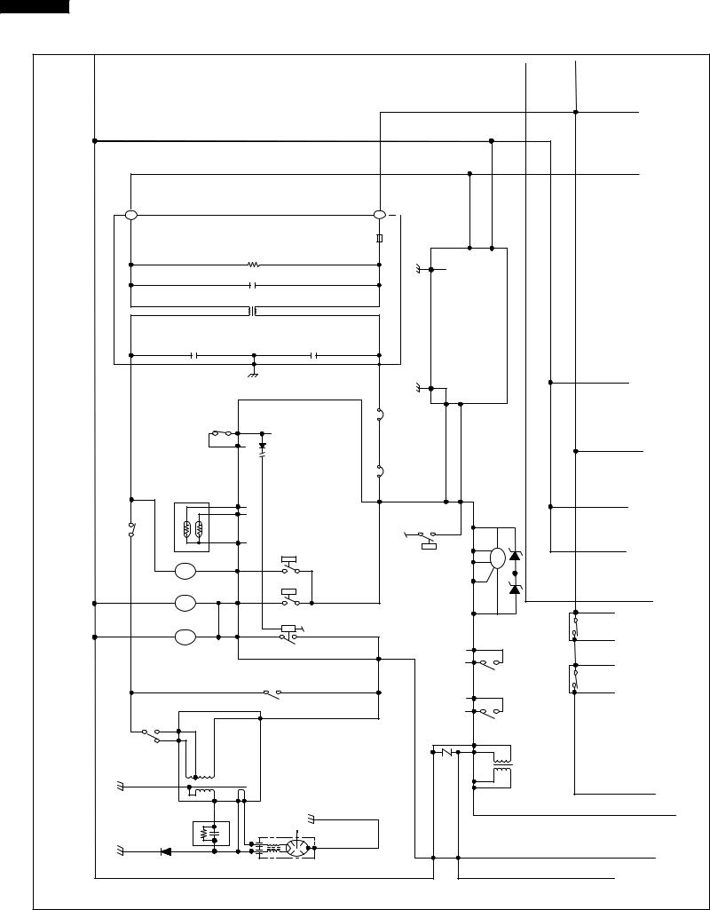
KB-3425LS/K/W KB-4425LS/K/W
MICROWAVE DRAWER SCHEMATIC (DETAIL)
|
|
|
|
|
|
|
|
|
|
|
|
L2 |
|
|
|
|
|
|
|
|
|
|
|
|
|
|
|
|
|
|
|
WHT |
|
|
|
|
|
|
|
|
|
|
|
|
|
|
|
|
|
|
|
|
|
|
|
|
|
|
|
|
|
|
|
|
|
|
|
N |
|
|
|
|
|
|
BLK |
|
|
|
|
|
|
|
|
|
|
|
|
|
|
|
|
|
|
|
|
L1 |
|
BLK |
|
|
|
|
|
|
|
|
|
|
|
|
|
|
|
|
|
|
|
|
|
|
|
|
|
|
|
|
|
|
|
|
|
|
|
|
|
|
|
|
|
|
|
|
|
|
|
|
|
|
|
RED |
|
|
|
|
|
|
|
|
|
|
|
|
|
L |
|
|
|
|
|
|
L |
|
|
|
|
|
|
|
|
|
|
||
|
|
|
|
|
|
|
|
|
|
FUSE |
|
|
|
|
BLK |
WHT |
|
|
|
|
RED |
|
|
|
|
|
|
|
|
|
|
|
|
|
|
|
|
|
|
|
|
|
|
|
|
|
|
|
|
|
|
|
|
|
|
20A |
|
|
|
|
|
|
|
|
|
|
|
|
|
|
|
|
|
|
RESISTOR 470 kohm 1/2W |
|
|
|
|
|
3 |
|
1 |
|
|
|
|
WHT |
|||
|
|
|
|
|
|
|
|
|
|
|
|
|
|
|
|
|
|
|
|
|||
|
|
|
|
|
LINE CROSS CAPACITOR 1.0uF 250V |
|
|
|
|
|
SWITCHING |
|
|
|
|
|
|
|||||
|
|
|
|
|
|
NOISE SUPRESSION COIL |
|
|
|
|
|
|
|
|
|
|
|
|||||
|
|
|
|
|
|
|
|
|
|
|
|
|
|
|
POWER |
|
|
|
|
|
|
|
|
|
|
|
LINE BYPASS CAPACITOR |
|
LINE BYPASS CAPACITOR |
|
|
|
|
SUPPLY |
|
|
|
|
|
|
|||||
MICROWAVE |
|
|
|
0.0033uF 250V |
|
|
|
0.0033uF 250V |
|
|
|
|
|
|
|
|
|
|
||||
|
|
|
|
|
|
|
|
|
|
|
|
|
|
UNIT |
|
|
|
|
|
|
||
|
|
|
|
|
|
|
|
|
|
|
RED |
|
|
|
|
|
|
|
|
|
|
|
|
|
|
|
|
DOOR |
|
|
|
|
|
OVEN THERMAL OUT-CUT OUT-CUT |
|
1 |
3 |
|
|
|
|
|
|
|
|
|
|
|
|
|
|
|
|
|
|
|
|
|
|
|
|
|
|
|
||||
|
|
|
|
|
SENSING |
|
|
|
|
|
|
|
|
|
|
|
|
|
||||
|
|
|
|
|
SWITCH |
M1 |
|
|
|
|
|
|
|
|
|
|
|
|
||||
|
|
|
|
|
|
WHT |
|
|
|
|
|
|
|
|
|
|
|
|
||||
|
|
|
|
|
|
|
M3 |
|
|
ORG |
|
|
|
|
DOOR |
|
|
|
||||
|
|
|
|
|
GRN |
|
|
|
|
|
|
|
|
|
|
|
||||||
|
|
|
|
|
|
|
|
|
|
|
|
|
|
|
|
|
||||||
|
|
|
|
|
|
|
|
|
|
BLK |
RED |
|
MOTOR |
|
|
|
|
|||||
|
|
|
|
HUMIDITY |
|
|
|
|
|
|
|
OPEN |
|
|
|
|||||||
|
|
|
|
|
|
|
|
|
|
|
|
MICROWAVE |
|
|
||||||||
DRAWER |
|
|
|
BRN RED BLK |
SENSOR |
|
F3 |
|
|
|
|
|
E1 |
|
E2 |
|
|
CLOSE- |
|
|
|
|
|
|
|
|
|
|
|
|
|
|
|
|
|
|
|
|
|||||||
|
|
|
|
|
F2 |
|
|
|
|
COM. |
|
|
|
|
|
|
||||||
WHT |
SWITCHSECONDARYINTELOCK |
BRN BLK |
|
|
|
|
CONTROLUNIT |
ORG |
MG THERMAL |
|
|
N1 |
RED |
|
|
DRAWER |
|
|
||||
RED |
|
|
|
|
|
|
|
|
|
|
||||||||||||
|
|
|
|
|
|
|
|
|
|
|
|
|||||||||||
|
|
F1 |
|
RY5 |
RY11 |
|
N2 |
BLK |
DM |
|
|
|
||||||||||
|
|
|
|
|
|
|
|
|
||||||||||||||
|
BLK |
|
|
|
N3 |
|
|
|
|
|||||||||||||
FM |
C1 |
|
|
|
ORG |
|
|
|
||||||||||||||
|
|
|
|
|
|
|
|
|
|
|||||||||||||
FAN MOTOR |
|
RY1 |
|
|
N4 |
YLW |
|
|
|
|||||||||||||
|
|
|
|
|
|
|
||||||||||||||||
|
|
|
|
|
|
|
|
|||||||||||||||
|
ORG |
ORG |
|
|
|
|
|
|
|
|
||||||||||||
|
|
|
|
WHT |
SM |
.O.N |
|
|
|
|
|
|
|
|
|
|
|
|
|
|
||
|
|
|
|
WHT |
ORG |
RED |
|
|
|
|
|
|
N5 |
BLU |
|
|
|
|
|
|
||
|
|
|
|
|
|
|
|
|
|
|
|
|
|
|
|
RY |
||||||
|
|
|
|
STIRRER MOTOR |
|
RY2 |
PRIMARY INTERLOCK |
|
|
|
|
|
|
|
|
|
|
|||||
|
|
|
|
WHT |
OL |
ORG |
RED |
|
|
RELAY |
|
|
|
|
|
|
|
|
|
|
|
C- |
|
|
|
|
.COM |
|
|
|
|
|
|
|
|
|
FRONT |
|
DOOR |
|
|||||
|
|
|
|
WHT |
|
|
|
|
|
|
|
|
M6 |
|
GRY |
|
|
|||||
|
|
|
|
|
|
|
|
|
|
|
|
|
|
|
|
|||||||
|
|
|
|
|
OVEN LAMP |
|
|
|
|
N.O. |
|
|
|
|
|
|||||||
|
|
|
|
|
|
|
|
|
|
|
M7 |
|
|
|
|
|||||||
|
|
|
|
|
|
|
|
|
|
|
|
|
|
|
|
|||||||
|
|
|
|
|
|
|
|
|
|
|
|
|
|
|
|
|
SWITCH |
|
||||
|
|
|
|
|
|
|
|
|
|
RED RED |
|
|
BRN |
|
|
|
POSITION |
ORG B-RY |
||||
|
|
|
|
|
|
BRN |
|
|
RED |
|
|
|
|
|
|
|
||||||
|
|
|
|
|
|
|
|
|
|
|
|
|
M14 |
|
BLK |
REAR |
|
|
|
|||
|
|
|
|
|
|
|
|
|
|
|
|
|
|
|
|
|
|
|
||||
|
|
|
|
|
|
|
|
|
MONITOR SWITCH |
|
|
|
|
|
|
|
|
|
|
|||
|
|
|
|
|
|
|
|
|
|
|
|
|
M13 |
|
|
|
SWITCH |
DOOR |
B |
|||
|
|
|
|
|
|
|
|
|
|
RED |
|
|
|
|
|
|
|
|||||
|
|
SWITCHVOLTAGE |
BRN |
|
|
|
|
|
|
|
|
|
BLK |
|
|
|
POSITION |
|||||
|
|
|
|
|
|
|
|
|
|
|
|
|
|
|
|
|
|
|||||
|
|
RED |
|
|
|
POWER TRANSFORMER |
|
|
|
|
|
|
|
|
|
|
|
|
||||
|
|
|
|
|
|
|
|
|
|
A1 A4 A6 |
|
BLK |
|
|
|
|
|
|||||
|
|
BLK |
|
|
|
|
|
|
|
|
|
|
|
|
LOW |
|
||||||
|
|
|
|
|
|
|
|
|
|
|
|
|
|
|
|
|||||||
|
|
|
|
|
|
|
|
|
|
|
|
WHT |
|
|
|
|||||||
|
|
|
|
|
|
|
|
|
|
|
|
|
|
VOLTAGE |
|
|||||||
|
|
|
|
|
|
|
|
|
|
|
|
BLU |
|
|
|
|
||||||
|
|
|
|
|
|
|
|
|
|
|
|
|
|
|
TRANSFORMER |
|
|
|||||
|
|
|
|
|
|
|
|
|
|
|
|
|
|
|
A2 |
|
YLW |
|
|
|
|
|
|
|
|
|
|
|
|
|
|
|
|
|
|
|
|
|
|
|
|
|
|
|
|
|
|
|
|
CAPACITOR |
|
|
|
|
|
|
|
|
|
|
|
|
|
|
|
|
|
|
|
|
|
|
1.00uF |
|
|
|
|
|
|
|
|
|
|
|
|
|
|
|
|
|
|
|
|
|
|
AC 2300V |
|
|
|
|
|
|
|
|
|
|
|
|
|
|
|
|
|
|
|
|
|
|
|
RECTIFIER |
|
|
|
MAGNETRON |
|
|
|
B1 |
|
B3 |
|
|
|
|
|
|
|
|
|
|
|
|
|
|
|
|
|
|
|
|
|
|
|
|
|
|
|
RED |
||
|
|
|
|
|
|
|
|
|
|
|
|
|
|
|
|
|
|
|
|
|
|
|
|
|
|
|
|
|
|
|
|
|
|
|
WHT |
|
|
|
|
|
|
|
|
|
|
|
|
|
|
|
|
|
|
|
|
16 |
|
|
|
|
|
|
|
|
|
|
|
|

KB-3425LS/K/W
KB-4425LS/K/W
RANGE SCHEMATIC (DETAIL)
N |
|
|
|
|
|
|
|
|
|
|
|
|
|
|
|
|
BLK |
|
|
|
|
|
|
|
|
BLK |
|
|
|
|
|
|
|
|
L1 |
|
RED |
|
|
|
|
|
|
BLK |
WHT |
|
|
|
|
BLK |
|
|
|
|
DOOR |
|
|
|
M4 |
|
|
|
|
|
|
|
|
|
|
||
|
SWITCH |
|
|
RED |
M5 |
|
|
|
|
|
|
|
|
|
|||
|
|
|
|
|
|
|
||
|
|
|
|
|
RED |
M9 |
|
CONTROL |
|
DOOR LOCK |
|
|
|
||||
|
|
YLW |
|
|
||||
|
MOTOR |
|
|
|
M10 |
|
||
|
|
|
|
|
|
|||
|
SWITCH |
|
|
BRN |
M8 |
|
||
|
|
|
|
|
|
|
UNIT |
|
|
|
|
|
|
ORG |
|
|
|
|
|
|
|
|
M11 |
|
OVEN |
|
|
THERMISTOR |
|
|
|
||||
|
|
|
M12 |
RY6 |
||||
|
|
|
|
ORG |
||||
|
|
|
|
|
|
|||
|
WHT |
|
FM |
YLW |
|
|
||
|
WHT |
|
C3 |
|
||||
|
CLOSS FLOW |
|
|
|||||
|
FAN MOTOR |
|
|
RY9 |
|
|||
|
|
|
|
|
BLK |
|
|
|
|
|
|
|
|
|
|
|
|
|
RED |
CM |
|
|
D1 |
|
|
|
|
RED |
|
|
|
|
|
|
|
|
BLU |
|
|
|
|
|
|
|
|
CONV. MOTOR |
|
RY8 |
|
||||
|
DOOR LOCK |
|
|
|
||||
|
|
|
|
|
||||
|
MOTOR |
|
BRN |
C7 |
|
|
||
|
WHT |
|
LM |
|
RED |
|||
|
WHT |
|
|
|
||||
|
|
|
|
|
|
|
RY7 |
|
|
OVEN LAMP |
|
C5 |
|
|
|||
|
WHT |
|
OL |
ORG |
|
|
||
|
|
|
|
|
||||
|
WHT |
|
|
|
|
|
||
|
|
|
|
|
|
|
|
|
|
|
|
|
|
|
|
RY10 |
|
|
|
YLW |
|
|
D3 |
|
|
|
|
|
|
|
|
|
|
||
C-RY |
|
WHT |
|
WHT |
E6 |
|
D5 |
|
|
WHT |
|
|
|
||||
|
|
|
GRY |
|
|
|||
|
|
|
|
|
E3 |
|
|
|
ORG |
BLK |
|
BLK |
|
|
|
||
|
|
|
|
|
||||
CONV. HEATER |
BLK |
|
|
|
|
|||
|
|
|
|
|
|
|||
B-RY |
|
|
|
|
|
|
||
|
|
|
WHT |
|
E5 |
RY3 |
|
|
|
|
|
|
|
|
|||
|
|
|
|
|
|
|
||
|
RED |
BLU |
|
|
|
|
COM. |
|
|
|
|
BLK |
BLK |
|
|
||
|
BOTTOM HEATER |
|
N.O. |
|
BLK |
|||
|
|
|
|
|
|
|
||
|
|
|
|
BLK |
|
|
|
|
|
TOP HEATER |
|
BLK |
|
|
|
|
|
|
|
|
|
|
|
|
||
|
|
RED |
|
|
|
|
|
|
|
|
|
|
COM. |
|
RY4 |
|
|
|
|
|
|
|
|
|
|
|
|
|
|
|
N.O. |
|
|
|
|
|
|
BRN |
|
|
|
|
|
|
RED |
|
|
|
|
|
RED |
|
|
OVEN THERMAL
CUT-OUT (THERMAL OVEN)
17

KB-3425LS/K/W KB-4425LS/K/W
TEST PROCEDURES
PROCEDURE |
COMPONENT TEST |
|
LETTER |
||
|
||
|
|
ATOUCH CONTROL PANEL ASSEMBLY TEST
The touch control panel consists of circuits including semiconductors such as LSI, ICs, etc. Therefore, unlike conventional microwave ovens, proper maintenance cannot be performed with only a voltmeter and ohmmeter.
In this service manual, the touch control panel assembly is divided into three units, Control Unit and Keyboard Unit and Power Unit, and troubleshooting by unit replacement is described according to the symptoms indicated.
Before testing,
1)Disconnect the power supply cord, and then disassemble as per "OVEN/MICROWAVE DRAWER DISASSEMBLY" page 40.
2)Open the drawer and block it open.
3)Discharge high voltage capacitor.
4)Disconnect the leads to the primary of the power transformer.
5)Ensure that these leads remain isolated from other components and oven chassis by using insulation tape.
1.Keyboard Unit. NOTE ;
1)Check Keyboard unit connection before replacement.
2)Reconnect all leads removed from components during testing.
3)Re-install the outer case (cabinet).
4)Reconnect the power supply cord after the outer case is installed.
5)Run the oven and check all functions.
The following symptoms indicate a defective keyboard unit.
a)When touching the pads, a certain pad produces no signal at all.
b)When touching a number pad, two figures or more are displayed.
c)When touching the pads, sometimes a pad produces no signal. If the Keyboard unit is defective.
1) Disconnect the power supply cord, and then remove outer case. 2) Open the door and block it open.
3) Discharge high voltage capacitor.
4) Replace the Keyboard unit.
5) Reconnect all leads removed from components during testing.
6) Re-install the covers.
7) Reconnect the power supply cord after the outer case is installed. 8) Run the oven and check all functions.
2.Control Unit
The following symptoms indicate a defective control unit. Before replacing the control unit, perform the Keyboard unit test (Procedure J) to determine if control unit is faulty.
2-1 In connection with indicators
a)At a certain digit, all or some segments do not light up.
b)At a certain digit, brightness is low.
c)Only one indicator does not light.
d)The corresponding segments of all digits do not light up; or they continue to light up.
e)Wrong figure appears.
f)A certain group of indicators do not light up.
g)The figure of all digits flicker.
2-2 Other possible problems caused by defective control unit.
a)Buzzer does not sound or continues to sound.
b)Clock does not operate properly.
c)Cooking is not possible.
3.Power Unit or Touch Control Transformer
a)Fan motor, stirrer motor, oven lamp or electrical parts do not turn on or do not turn off.
b)Digital display on the control unit does not show anything.
When testing is completed,
1)Disconnect the power supply cord, and then disassemble as per "OVEN/MICROWAVE DRAWER DISASSEMBLY" page 40.
2)Open the drawer and block it open.
3)Discharge high voltage capacitor.
18

TEST PROCEDURES
PROCEDURE |
COMPONENT TEST |
|
LETTER |
||
|
KB-3425LS/K/W KB-4425LS/K/W
|
4) |
Reconnect all leads removed from components during testing. |
|
5) |
Re-install the covers. |
|
6) |
Reconnect the power supply cord after the outer case is installed. |
|
7) |
Run the oven and check all functions. |
|
|
|
B |
KEYBOARD UNIT TEST |
|
|
1. Disconnect the power supply cord, and then disassemble as per "OVEN/MICROWAVE DRAWER |
|
|
|
DISASSEMBLY" page 40. |
2.Open the drawer and block it open.
3.Discharge high voltage capacitor.
4.If the display fails to clear when the STOP/CLEAR pad is depressed, first verify the wire harness and connectors are making good contact between the control unit and the keyboard, verify that the door sensing switch operates properly; that is the contacts are closed when the door is closed and open when the door is open.
5.Remove the old keyboard unit and install the new keyboed unit (as the normal keyboard unit).
6.Reconnect the wire harness to the keyboard unit.
7.If the control unit responds by clearing with a beep when the stop/clear pad is touched, the old keyboard unit is faulty and must be replaced. If the control unit does not respond, it is faulty and must be replaced. If a specific pad does not respond, the above method may be used (after clearing the control unit) to determine if the control unit or keyboed unit is at fault.
8.Reconnect all leads removed from components during testing.
9.Re-install the covers.
10.Reconnect the power supply cord after the outer case is installed.
11.Run the oven and check all functions.
CRELAY TEST
1.Disconnect the power supply cord, and then disassemble as per "OVEN/MICROWAVE DRAWER DISASSEMBLY" page 40.
2.Open the drawer and block it open.
3.Discharge high voltage capacitor.
4.Disconnect the leads to the primary of the power transformer.
5.Ensure that these leads remain isolated from other components and oven chassis by using insulation tape.
6.After that procedure, re-connect the power supply cord.
7.Remove the covers and check voltage between Pin Nos. 1 and 3 of the 2 pin connector (CN-B) on the power unit with an A.C. voltmeter.
The meter should indicate 116 or 120 volts, if not check oven circuit.
RY1 and RY2 Relay Test
These relays are operated by D.C. voltage
Check voltage at the relay coil with a D.C. voltmeter during the microwave cooking operation. DC. voltage indicated - Defective relay.
DC. voltage not indicated - Check diode which is connected to the relay coil. If diode is good, control unit is defective.
RELAY SYMBOL |
OPERATIONAL VOLTAGE |
CONNECTED COMPONENTS |
RY1 |
Approx. 18V D.C. |
Oven lamp / Stirrer motor |
RY2 |
Approx. 18V D.C. |
Power transformer |
RY3 |
Approx. 18V D.C. |
Oven common relay |
RY4 |
Approx. 18V D.C. |
Top heater |
RY5 |
Approx. 24V D.C. |
Fan motor (Microwave) |
RY6 |
Approx. 24V D.C. |
Fan motor (Oven) |
RY7 |
Approx. 24V D.C. |
Oven lamp (Oven) |
RY8 |
Approx. 24V D.C. |
Door lock motor (Oven) |
RY9 |
Approx. 24V D.C. |
Convection motor |
RY10 |
Approx. 24V D.C. |
Warmer (Cook top) |
RY11 |
Approx. 24V D.C. |
Switching power supply |
RY-B |
Approx. 24V D.C. |
Bottom heater |
RY-C |
Approx. 24V D.C. |
Convection heater |
|
|
|
19

KB-3425LS/K/W KB-4425LS/K/W
TEST PROCEDURES
PROCEDURE |
COMPONENT TEST |
|
LETTER |
||
|
8.Reconnect all leads removed from components during testing.
9.Re-install the covers.
10.Reconnect the power supply cord after the cabinets are installed.
11.Run the drawer and check all function.
D |
DEFROST TEST |
|
|
|
|
|
|
|
|
||
|
WARNING : The unit should be fully assembled before following procedure. |
||||||||||
|
(1) Place one cup of water in the center of the turntable tray in the oven cavity. |
||||||||||
|
(2) Close the door, touch the Stop/Clear (M) pad and touch the Defrost pad on the LCD. Then touch |
||||||||||
|
the Steaks/Chops pad on the LCD. And touch the number pad 5 on the LCD. (Now, weight 0.5lb is |
||||||||||
|
set.) And then touch the start pad on the LCD. |
|
|
|
|
|
|||||
|
(3) The oven is in Defrost cooking condition. |
|
|
|
|
|
|||||
|
(4) The oven will operate as follows |
|
|
|
|
|
|
||||
|
|
|
|
|
|
|
|
|
|
|
|
|
|
|
WEIGHT |
1ST STAGE |
2ND STAGE |
3RD. STAGE |
|
||||
|
|
|
|
|
|
|
|
|
|
|
|
|
|
|
|
LEVEL |
TIME |
LEVEL |
TIME |
LEVEL |
|
TIME |
|
|
|
|
0.5lb |
60% |
20sec. |
40% |
20sec. |
30% |
|
45sec. |
|
|
(5) If improper operation is indicated, the control unit is probably defective and should be checked. |
||||||||||
|
|
||||||||||
E |
PROCEDURES TO BE TAKEN WHEN THE FUSE ON THE PRINTED WIRING BOARD (PWB) IS OPEN. |
||||||||||
|
To protect the electronic circuits, this model is provided with a fuse added to the primary on the PWB. |
||||||||||
|
1. Fuse check and repairs. |
|
|
|
|
|
|
|
|||
|
1) Disconnect the power supply cord, and then disassemble as per "OVEN/MICROWAVE DRAWER |
||||||||||
|
DISASSEMBLY" page 40. |
|
|
|
|
|
|
|
|||
|
2) |
Open the drawer and block it open. |
|
|
|
|
|
|
|||
|
3) |
Discharge high voltage capacitor. |
|
|
|
|
|
|
|||
|
4) |
If the Fuse is blown, replace power unit. |
|
|
|
|
|
||||
|
5) |
Make a visual inspection of the varistor. Check for burned damage. If the varistor has been |
|||||||||
|
|
burned, replace the power unit. |
|
|
|
|
|
|
|||
|
6) |
Examine the touch control transformer with a tester for the presence of layer short-circuit (check |
|||||||||
|
|
the primary coil resistance which is approximately 60Ω ± 10%). If any abnormal condition is |
|||||||||
|
|
detected, replace the touch control transformer. |
|
|
|
|
|||||
|
7) |
Reconnect all leads removed from components during testing. |
|
|
|||||||
|
8) |
Re-install the covers. |
|
|
|
|
|
|
|
||
|
9) |
Reconnect the power supply cord after the outer case is installed. |
|
|
|||||||
|
10) |
Run the oven and check all functions. |
|
|
|
|
|
||||
2.Follow the troubleshooting guide given below, if indicator does not light up after above check and repairs are finished.
1)Disconnect the power supply cord, and then disassemble as per "OVEN/MICROWAVE DRAWER DISASSEMBLY" page 40.
2)Open the door and block it open.
3)Discharge high voltage capacitor.
4)Disconnect the leads to the primary of the power transformer.
5)Ensure that these leads remain isolated from other components and oven chassis by using insulation tape.
6)After that procedure, re-connect the power supply cord.
7)Follow the troubleshooting guide given below for repair.
20
TEST PROCEDURES
PROCEDURE |
COMPONENT TEST |
|
LETTER |
||
|
KB-3425LS/K/W KB-4425LS/K/W
STEPS |
OCCURRENCE |
CAUSE OR CORRECTION |
|
|
|
1 |
The rated AC voltage is not present between |
Check supply voltage and oven power cord. |
|
Pin Nos. 1and 3 of the 2-pin connecter (CN-B). |
|
|
|
|
2 |
The rated AC voltage is present at primary |
Touch control transformer or secondary circuit defective. |
|
side of touch control transformer. |
Check and replace touch control transformer or power |
|
|
unit . |
|
|
|
8)Reconnect all leads removed from components during testing.
9)Re-install the covers.
10)Reconnect the power supply cord after the cabinets are installed.
11)Run the oven and check all functions.
F |
AH SENSOR TEST |
|
|
Checking the initial sensor cooking condition |
|
|
WARNING : The oven should be fully assembled before following procedure. |
|
|
(1) |
The oven should be plugged in at least two minutes before sensor cooking. |
|
(2) |
Room temperature should not exceed 95oF (35oC). |
|
(3) |
The unit should not be installed in any area where heat and steam are generated.The unit should not be |
|
|
installed, for example, next to a conventional surface unit. Refer to the “INSTALLATION INSTRUCTIONS” |
|
|
of the operation manual. |
|
(4) |
Exhaust vents are provided on the back of the unit for proper cooling and air flow in the cavity. To permit |
|
|
adequate ventilation, be sure to install so as not to block these vents. There should be some space for |
|
|
air circulation. |
|
(5) |
Be sure the exterior of the cooking container and the interior of the oven are dry. Wipe off any moisture |
|
|
with a dry cloth or paper towel. |
|
(6) |
The Sensor works with food at normal storage temperature. For example, chicken pieces would be at |
|
|
refrigerator temperature and canned soup at room temperature. |
|
(7) |
Avoid using aerosol sprays or cleaning solvents near the oven while using Sensor settings. The sensor |
|
|
will detect the vapor given of by the spray and turn off before food is properly cooked. |
|
(8) |
If the sensor has not detected the vapor of the food, ERROR will appear and the oven will shut off. |
Water load cooking test
WARNING : The oven should be fully assembled before following procedure.
Make sure the oven has been plugged in at least two minutes before checking sensor cook operation. The cabinet should be installed and screws tightened.
(1)Fill approximately 200 milliliters (7.2 oz) of tap water in a 1000 milliliter measuring cup.
(2)Place the container on the center of tray in the oven cavity.
(3)Close the door.
(4) |
Touch the UPER MICROWAVE OVEN pad, |
<pad,< pad, START MINUTE PLUS pad and the |
|
SENSOR LOAD pad on the LCD. And touch the number pad 4 once. Now, the oven is in the sensor |
|
|
cooking condition, and "20BIT" and "MICRO" will appear in the display. |
|
(5) |
The oven will operate for the first 16 seconds, without generating microwave energy. |
|
NOTE: ERROR will appear if the door is opened or STOP/CLEAR pad is touched during first stage of sensor cooking.
(6) After approximately 16 seconds, microwave energy is produced.
If ERROR is displayed or the oven does not turn off, replace the AH sensor or check the control unit, refer to explanation below.
TESTING METHOD FOR AH SENSOR AND/OR CONTROL UNIT
To determine if the sensor is defective, the simplest method is to replace it with a new replacement sensor.
1)Disconnect the power supply cord, and then disassemble as per "OVEN/MICROWAVE DRAWER DISASSEMBLY" page 40.
2)Open the drawer and block it open.
3)Discharge high voltage capacitor.
4)Remove the AH sensor.
21
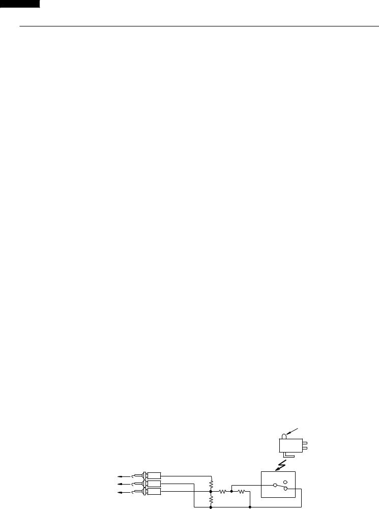
KB-3425LS/K/W KB-4425LS/K/W
TEST PROCEDURES
PROCEDURE |
COMPONENT TEST |
|
LETTER |
||
|
(5)Install the new AH sensor.
(6)Reconnect all leads removed from components during testing.
(7)Re-install the outer case (cabinet).
(8)Reconnect the power supply cord after the cabinets are installed.
(9)Reconnect the oven to the power supply and check the sensor cook operation as follows: 9-1. Fill approximately 200 milliliters (7.2 oz) of tap water in a 1000 milliliter measuring cup.
9-2. Place the container on the center of tray in the oven cavity.
9-3. |
Close the door. |
9-4. |
Touch the UPER MICROWAVE OVEN pad, <pad,< pad, START MINUTE PLUS pad and the |
|
SENSOR LOAD pad on the LCD. And touch the number pad 4 once. |
9-5. |
The control panel is in automatic Sensor operation. |
9-6. |
The oven turns off automatically, and the time for detecting moisture will be displayed. |
If new sensor dose not operate properly, the problem is with the control unit, and refer to explanation below.
CHECKING CONTROL UNIT
(1)Disconnect the power supply cord, and then disassemble as per "OVEN/MICROWAVE DRAWER DISASSEMBLY" page 40.
(2)Open the drawer and block it open.
(3)Discharge high voltage capacitor.
(4)Disconnect the sensor connector that is mounted to control panel.
(5)Then connect the dummy resistor circuit (see fig.) to the sensor connector of control panel.
(6)Disconnect the leads to the primary of the power transformer.
(7)Ensure that these leads remain isolated from other components and oven chassis by using insulation tape.
(8)After that procedure, re-connect the power supply cord.
(9)Check the sensor cook operation proceed as follows: 9-1. Close the door.
9-2. |
Touch the UPER MICROWAVE OVEN pad, <pad,< pad, START MINUTE PLUS pad and the |
|
SENSOR LOAD pad on the LCD. And touch the number pad 4 once. |
9-3. The control panel is in the sensor cooking operation. |
|
9-4. |
After approximately 25 seconds, push plunger of select switch for more than 3 seconds.This condition |
|
is same as judgement by AH sensor. |
9-5. |
After approximately 3 seconds, the display shows “ X X . X X “ which is the time for detecting |
|
moisture. |
|
If the above is not the case, the control unit is probably defective. |
|
If the above is proper, the AH sensor is probably defective. |
(10)Disconnect the power supply cord, and the covers.
(11)Open the door and block it open.
(12)Discharge high voltage capacitor.
(13)Disconnect the dummy resistor circuit from the sensor connector of control panel.
(14)Carry out necessary repair.
(15)Reconnect all leads removed from components during testing and repairing.
(16)Re-install the covers.
(17)Reconnect the power supply cord after the cabinets are installed. Run the oven and check all functions.
(18) Carry out "Water load cooking test" again and ensure that the oven works properly.
R1, R2 : |
22Ω ± 1% 1/2W |
|
|
|
|
R3 : 4.3kΩ ± 5% 1/4W |
|
|
|
Plunger |
|
R4 : |
1MΩ ± 5% 1/4W |
|
|
|
NC |
|
|
|
|
|
|
|
|
|
|
|
NO |
|
To connector (F) |
|
|
|
COM |
|
on Control Unit. |
|
|
|
|
|
|
|
|
|
|
F-1 |
1 |
|
|
|
NO |
2 |
|
|
COM |
||
F-2 |
R1 |
|
|
||
3 |
|
|
|
||
|
|
|
|
|
|
F-3 |
|
R2 |
R3 |
R4 |
NC |
|
CONNECTOR |
|
|||
|
|
|
|
|
|
22
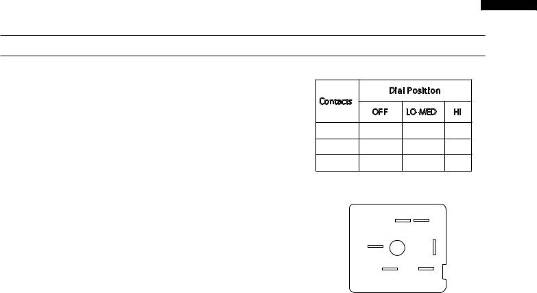
TEST PROCEDURES
PROCEDURE |
COMPONENT TEST |
|
LETTER |
||
|
KB-3425LS/K/W KB-4425LS/K/W
G |
SURFACE ELEMENT CONTROL SYSTEMS |
Dial Position |
|
|||
|
|
|
|
|
|
|
|
|
|
Contacts |
|
|
|
|
|
|
|
OFF |
LO-MED |
HI |
|
Two types of surface elements control systems are |
P2 - P |
O |
X |
X |
|
|
covered in this manual. |
|||||
|
|
|
|
|
||
|
1. |
Standard infinite switch. |
P2 - 4 |
O |
X |
X |
|
P1 - 2 |
O |
X - C |
X |
||
|
|
|
||||
|
2. |
Dual infinite switch. |
O |
- open |
X - closed |
|
|
|
|
||||
|
Standard infinite switch: |
|
|
P1 |
|
|
|
|
|
|
|
||
|
The surface elements and standard infinite switches pro- |
|
|
2 |
|
|
|
vide an infinite choice of heat settings for cooking. Con- |
|
4 |
|
||
|
|
|
|
|||
|
trols are safety type and must be pushed in before turn- |
|
|
|
|
|
|
ing. All surface controls are marked on the control panel |
|
PILOT |
P2 |
|
|
|
for their respective heating element. Power is supplied |
|
|
|
|
|
|
to the surface elements through the infinite switch con- |
|
|
|
|
|
|
tacts P2-4 and P1-2. During actual surface element |
|
|
|
|
|
|
operation, if the control is set to the high position con- |
|
|
|
|
|
|
tacts P1-2 are lock closed providing continuous power |
Element does not heat: |
|
|
||
|
to the element. In all other setting contacts L2-H2 will |
|
|
|
|
|
|
cycle to maintain the correct heat setting. Contacts L1- |
Checking the system with a Voltmeter, if the element |
||||
|
P provide power to the surface element indicator light. |
does not heat up. |
|
|
||
Troubleshooting: |
1. |
Remove the back of the control panel to |
|
There are four ways a surface control system with a |
|
expose the switch terminals. |
|
|
|
||
standard infinite switch can fail. |
2. |
With a Voltmeter set for AC on a scale higher |
|
1. |
The element does not heat. |
|
than 240 Volts measure the voltage drop |
|
between terminals P2 and P1. If the meter |
||
2. |
The switch does not cycle the element off and |
|
reads zero the wiring between the main |
|
terminal block on the range and the switch is |
||
|
on when set to a position other than high. |
|
open. If the meter reads line to line voltage |
|
|
|
(around 240 VAC) go to step 3. |
3.The element operates correctly, but the
|
indicator light does not glow. |
3. |
With the switch turned to the high position |
4. |
Indicator light glows with all infinite switches |
|
measure the voltage drop between terminals |
|
4 and 2. If the meter reads zero the switch |
||
|
in the off position. |
|
is defective. If the meter reads line to line |
|
NOTE: If the indicator light glows very dimly |
|
voltage the switch is good. If the range has |
|
|
standard elements go to step 4. If the range |
|
|
with all the switches in the off position. This |
|
has a glass smooth go to step 5. |
|
problem is caused by a capacitive feed over in |
|
|
|
the wiring and can be corrected by connecting |
4. |
Remove the element and measure the |
|
a 100,000 Ohm 1/4 watt resistor in parallel with |
|
voltage drop between terminals of the terminal |
|
the light. |
|
block. If the meter reads zero the terminal |
Continuity tests can be performed on the infinite switch |
|
block or the wiring between the switch and the |
|
|
terminal block is open. If the meter reads line |
||
contacts. All tests should be performed with power to |
|
to line voltage the element is defective. |
|
the range disconnected, and wiring removed from the |
|
|
|
switch. Set an ohmmeter on R X 1K scale and check |
|
NOTE: Always inspect the terminal block for |
|
the contacts in the following chart and switch terminal |
|
burnt spots that can cause poor connection. |
|
diagram. |
5. |
Raise the top and locate the two terminals on |
|
|
|
||
|
|
|
the element that the wires from 4 and 2 are |
|
|
|
on. Measure the voltage drop between the two |
|
|
|
terminals. If the meter reads zero the wires |
23
 Loading...