SAMSUNG S821 Service Manual

Page 1
WASHING MACHINE
S621GWL/YLW
S621GWS/YLW
S821GWL/YLW
S821GWS/YLW
Manual
SERVICE
WASHING MACHINE
CONTENTS
Caution for the safety during servicing
1. SPECIFICATIONS
2. SAFETY DEVICES
3. OVERVIEW OF THE WASHING MACHINE
5. MAIN FUNCTION
6. TECHNICAL POINT
7. GENERAL ERROR FUNCTION
8. TROUBLE DIAGNOSIS
9. TEST MODE
10. DESIGNATION OF MAIN COMPONENTS
11. PCB SCHEMATIC DIAGRAM
11-1. PCB CIRCUIT DIAGRAM
12. SETTING UP A WASH MACHINE
13. ASSEMBLE AND DISASSEMBLE
14
. TOOLS FOR DISASSEMBLY AND ASSEMBLY
15. EXPLODED VIEW AND PARTS LIST
Page 2
Caution for the safety during servicing
1. Do not allow the customer to repair the product.
The person may be injured or the product life may be shortened.
2. Execute A/S after unplugging the power supply unit.
Be care of the electric shock.
3. Do not plug several plugs in the same outlet.
It may cause the fire due to overheat.
4. Check the damage, pressing or burning of the power plug or outlet.
Replace it promptly if it has problem.((may cause the electric shock or fire)
5. Do not clean the main body with the water.
It may cause the electric shock and fire and shorten the product life))
6. The wiring of the harness shall be free from the moisture and tightened during serving.
It shall not be deviated by certain impact.
7. Remove any dust or filth on the housing section,wiring section,connection section during servicing.
Protect the cause of the fire such as the tracking,and etc.
8. Check any mark of the moisture on the electrical parts, harness section and etc.
Replace the parts or remove the moisture.
9. Check the assembly status of the parts after servicing.
Maintain the status before servicing.
10. Pull out the power cord with holding the plug.
Be care of the electric shock and fire when the cord is damaged.
11. Unplug the power plug from the outlet when the wash machine is not used.
Be care of the electric shock and fire due to the strike of the lightening.
12. Do not use or store the spray or flammable materials(including gasoline,alcohol and etc.)
around the wash machine.
Be care of the explosion or fire due to the electric spark.
13. Do not put the bowl of water or wet laundry on the wash machine.
If the water is penetrated to the wash machine, this may cause the electric shock or fire.
14. Do not install the wash machine in the place where the snow or rain falls.
It may cause the electric shock and fire and shorten the product life.
15. Do not push the control buttons with the awl,pin, or sharp materials.
It may the electric shock and trouble.
16. Check the wash machine is leveled horizontally and installed properly on the floor.
The vibration may shorten the product life.
17. Joint the wire by the connector correctly.
When the wire is jointed by the tape, this may cause the fire due to the tracking.
18. When the wash machine is to be laid for the service, put the pad on the floor and lay the product at
side slowly.
If the wash machine is laid front, the relay may be damaged by the tub.
19. When the wash-heater is replaced, check it is inserted in the bracket-heater and screw the nut.
If the wash--is not inserted in the bracket-heater properly, this may cause the noise and
leakage since it is contacted to the drum.
- 1 -
Page 3
1. Specifications
WASH TYPE
DIMENSION
WATER PRESSURE
WEIGHT
WASH and SPIN CAPACITY
POWER CONSUMPTION
WATER CONSUMPTION
SPIN REVOLUTION
FRONT LOADING TYPE GROSS W 680mm X D 478mm X H 892mm NET W 598mm X D 340mm X H 844mm
50 kPa ~ 800 kPa
GROSS 58 kg
NET 55 kg
3.5 kg (DRY LAUNDRY)
220 V 110 W
WASHING
WASHING and HEATING
MODEL S821 S621
SPIN
220-240V
PUMPING 34 W
MODEL S821 S621 rpm 800 600
240 V 110 W
220 V 900 W
240 V 1050 W
200 W 170 W
43ℓ(STANDARD COURSE)
- 2 -
Page 4
2. Safety Devices
We adapt 5 safety devices for users to use this wash machine safely.
1) Balancing device (ASSY-Main PCB)
When the laundry is out of balance, to prevent the noises and vibrations, the unbalance detecting sensor helps the laundry laid even and continue the dehydating process.
2) Anti-over water supply device
Because water supply value is broken, once water is supplied to the 2/3 level of the door, the water supplied is drained automatically, Over -flow error is displayed on the panel
3) Temperature-regulating device(thermistor)
To prevent over-heating over the temperature setted up, THERMISTOR senses the temperature of the machine continuously and helps the wash machine to work at the temperature given by users.
4 Overheating- controlling system
Under the circumstances of THERMISTOR inferiority or abnormal condition, if wash-heater is overheated, automatically, assy -thermal fuse cuts off the power supply to protect the machine to keep it safe.
5) Delicate clothing safeguard function(ASSY-Main PCB)
To protect the clothings which is weak to high temperature, the wash machine senses the temperature inside the washing tub. if the temperature rises over 50℃wool washing course and Delicate washing course display abnormal water temperature on the panel , after draining the water.
- 3 -
Page 5
3. Overview of the Washing Machine
- 4 -
Page 6
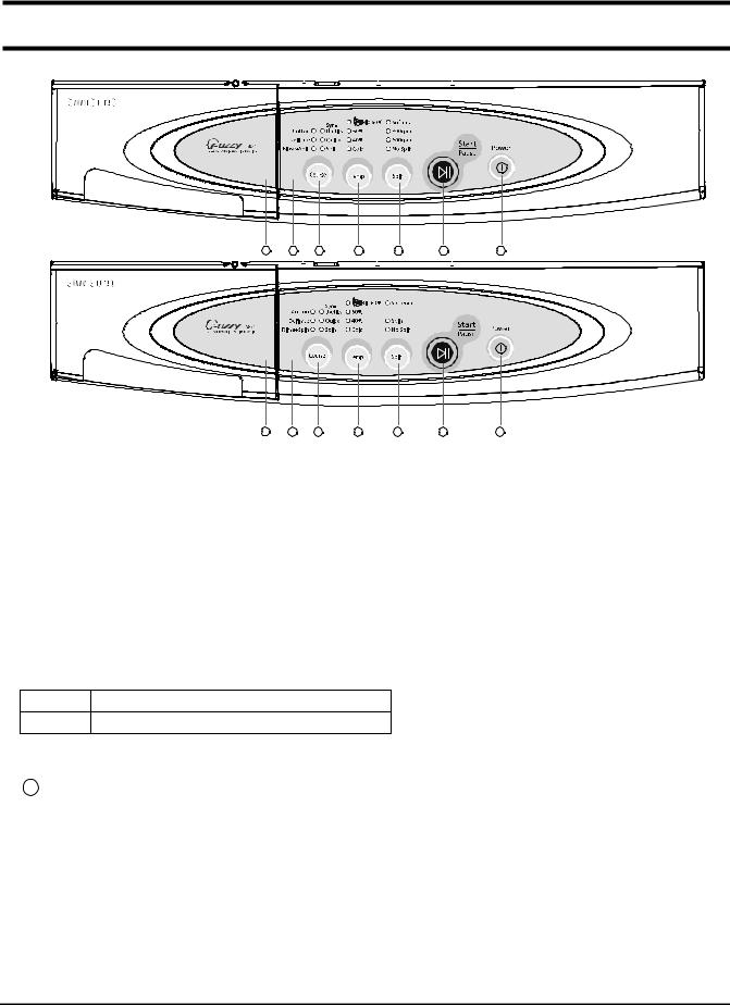
4. Overview of the control panel
S821
1
S621
2 3 4 5 6
1
2 3 4 5 6
1. Detergent dispenser
2. Display panel
Displays wash cycle and error messages by LED lamps.
3. Course button
Press the button repeatedly to select one of the six availabel wash program.
{Cotton.Synthetics.Delicates .Quick.Rinse+Spin.Spin.Cotton }.
4444....
Temperature selection button
Press the button repeatedly to cycle through the available water temperature options
(cold, 40 °C , 60 ° C and Bio 60 ° C).
Bio 60°C : To improve the Wash efficiency, heating during 30 min.
*
5. Spin selection button
Press the button repeatedly to cycle through the available spin speed options.
7
7
S821
no spin, 600, 800 rpm
S621 no spin, 600 rpm
6. Start/Pause button
Press to pause and restart programs.
7777.... 1111((((
On/Off) button
Press once to turn the washing machine on, press again to turn the washing machine off. If the washing machine power is left on for longer than 10 minutes without any buttons being touched, the power automatically turns off.
- 5 -
Page 7
5. Main function
1) Auto power S/W off function
After power on, the auto power S/W off function automatically switches power off for you if you do not press selection button for 10 minutes
After selecting the function, the auto power S/W off function automatically switches power off for you if you do not press start/pause button for 10 minutes
After finishing the last function, the auto power S/W off function automatically switches power off for you if you do not re-select the course button or manual button
2) Door open function
If door is open during the operating, all operating is halted, and door error message will be displayed and error melody will coming out
Door open error can be cleared by colosing the door. the operating keeps going on
3) No spin function
If no spin function selected, the operating is finished after last rinse
- 6 -
Page 8
5. Main function
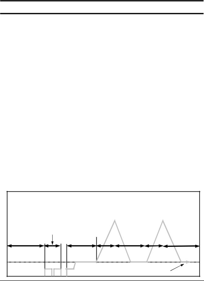
4) Power-out compensation function
If power is out on selected process, the process before power out is stored to EEPROM, once power is back the process before power out continues.
When power is back, washing process starts from the process at the point of the power out, rinse/drain process starts from the initial process.
POWER-OUT COMPENSATION FUNCTION PROCESS
WASHINGSTART
POWER OUT
SAVE DATA to EEPROM
READ DATA
(PROCESS+TIME)
5) Water heater Error function
This function starts working, when the heater works abnormally. (this function begins sensing the heater 1 minutes later, after the heater operating)
The value of the initial thermistor(A1) is compared with that of the thermistor(A2) in 2 minutes (Y=A2-A1)
- For 10 minutes, the variance of temperature(Y) is less than 2℃"course led 6ea on 40℃/60℃led on" message is displayed on the panel.
The value of the initial thermistor(A1) is compared with that of the thermistor(A2) in 2 minutes (Y=A2-A1)
- For 2 minute the variance of temperature increases more than 4.5℃(0.2148V) "course led 6ea on cold/60 led on" message is displayed on the panel.
At this time heater, Error "course led 6ea on cold/60℃led on" is displayed and all working process off
The heater operating continues during heating hours, if washing hour is left over, the residual washing process keeps going without heating.
POWER BACK
MICOM RESTORE
RESTART
PROCESS
RINSE/DRAIN
START
SAVE DATA to EEPROM
RINSE/DRAIN
PROCESS
POWER OUT
POWER BACK
MICOM RESTORE
FINISH
- 7 -
Page 9
5. Main function
6) Fuzzy washing function ( weight-sensing)
After finishing initial water supply, when the fall of the water level needs supplementary water supply, Sensing function perceives the weght with the supplementary water supply numbers and starts to work. Under the course of Cotton, if the supplementary water supply numbers become 3 - 4 times the function is going at default condition ( high water level ), if 1-2 below that is going at middle level, if 0 below low water level, heating hours and rinse hours depend on the above data.
Washing hours
Cotton
High Default Default
Middle Default-12 min 22.80KHZ
Low Default-25 min 23.30KHZ
After sensing weight, above hours is decreased from above default hours
7) Bubble -detecting function
At the each condition of washing&dehydrating , rinse&dehydrating , hydrating, bubble -detecting function works, this function works 5times normally, if the function detects bubbles at 6 times , the bubble-detecting function stops and go on to the next process.
The bubble-detecting function during washing & dehydrating to rinse & dehydrating after 2 times instant dehydrating and before main dehydrating, if the water level is under 25.45KHZ, Bubble
Detecting function thinks there are bubbles and add the bubbles-removing rinse, needing hours are above hours and 6 min 40 sec.
The bubble-detecting function during single hydrating process after 2 times instant dehydrating and before main dehydrating , if the water level is 25.45KHZ below or during main dehydrating, water level data is 23.80KHZ below Bubble-detecting function thinks there are bubbles and add the bubbles-removing rinse 1 times, needing hours are above hours and 5 min 50 sec.
Rinse water level
Bubble-detecting function operating process
20 sec
laundry scattering
draining &reverse
1 min 20sec
unbalance
detecting range
- 8 -
210rpm
5sec20sec 15sec 5sec
bubble detection
(default water level 25.45KHZ below)
210rpm
15sec
Page 10
5. Main function
8) Unbalance detecting & laundry balance positioning system
Just before the hydrating process and just after reversal rotation for balancing laundry position, this function is carried out
The initial 6 sec is the period of reversal rotation for balancing laundry position , Drum rotates 50rpm for initial 6 sec
Next 10 sec, the rotation increases the speed from 50 rpm to 90 rpm slowly
During the next 18 sec, drum rotates at the speed of 90 rpm, the sensor decides the degree of laundry unbalance with TACHO data which is attached to motor
If the degree of unbalanced laundry is over 6 times to default value, laundry balancing system carryies out feed back process 6 times
- 9 -
Page 11
6. Technical point
1) Motor on/off time at each course
Washing Rinse
Course
Cw Off Ccw Off Cw Off Ccw Off
Cotton
Synthetics
Delicates
Quick
13 3 13 3 10 5 10 5 50
7 8 7 8 7 8 7 8 40
5 10 5 10 5 10 5 10 30
12 3 12 3 10 5 10 5 45
2) Final dehydrating r.p.m at each course
Model
Course
Cotton
Synthetics
S821 S621
800 600
800 600
unit:sec
Motor r.p.m
unit:rpm
Delicates
Quick
You can change the r.p.m to the above a table by use spin button under no spin situation.
600 600
800 600
- 10 -
Page 12
6. Technical point
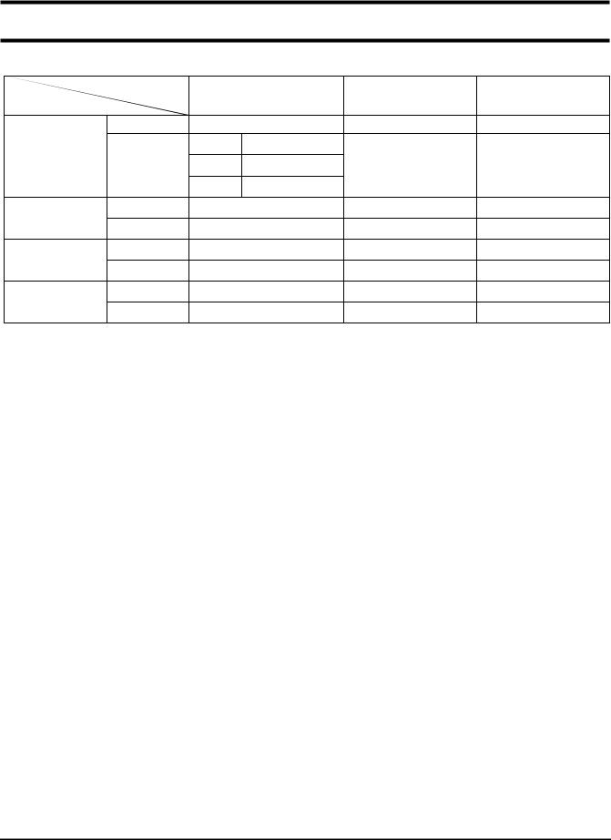
3) The water level data at each course
Course
Cotton
Synthetics
Delicates
Quick
Water level
Washing
Rinse
Washing
Rinse
Washing
Rinse
Washing
Rinse
Default water level(khz)
23.50 24.00 23.70
large 22.45
small 23.30
23.50 24.00 23.70
22.45 24.00 23.50
22.80 23.55 23.35
22.65 23.55 23.35
23.50 24.00 23.70
22.45 24.00 23.50
4) The other water level data
The water data unter each conditon
Supplemetary water
START(Khz)
24.00 23.50middle 22.80
unit:Khz
Supplemetary water
end(khz)
1st water supply (only preparation)
Overflow error
Bubble
detectingatwashing/rinse/dehydrating
Bubble detecting rinse water level
Water level which can open door
Water level which can drive heater
Water level which can reset the drain
If water level is 15KHZ below or 30 KHZ above , sensor-pressur is out of order so needs changing.
24.60 1st water supply level to washing tub
20.50 The water supplied reach 2/3 of door
25.45 Bubble -detecting water level
22.00 The water level which can detect bubbles
over
23.80
24.50 Safety water level of wash heater
24.50 The water level can be detected after 1st draining
It is possible to open the door
unit:Khz
- 11 -
Page 13
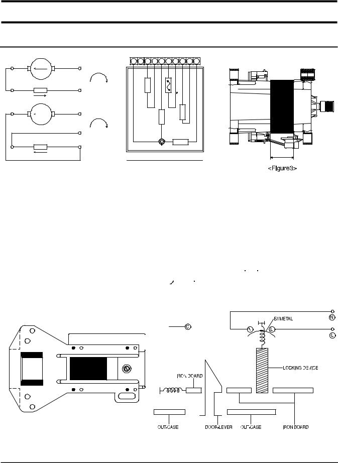
10. Designation of Main Components
10-1 Normal / Reverse Revolution of Motor and R. P. M. Control
89
510
89
Rotor
Stator coil
Rotor
Stator coil
+
CW
-
+
CCW
5
-
10
5
<Figure1> <Figure2>
(
±7%)
Resistance
STATOR(51) ROTOR(8.9) TACHO(3.4) PROTECTOR(6.7) "H"(mm) Code-No. Remark
2.08
1.99
38.8
value
Rated
value
10-2 Door safety Device
12345678910
D E E P S
­H G
I H
E
H C A T
R
P
O
S
-
T
)
E
C
C
L
E
0
D
T
5
D
O
I
1
(
R
M
P
R
STATOR
O T O R
R O T A T S
D E
O
WASHING MOTOR
0 30 DC31-00002H S821
220~240V/50Hz
H
S621
When Door is closed, door stay closed. if "set" is operated, power supplied to , wires have bymetal keep
the door closed, and electronical power flows between and make it operate.
- 23 -
Page 14
10-3 Heater
1) Capacity : AC 230V/800W
2) Location : Bottom of TUB
3) Function : Raise the water temperature supplied at the wash process.
4) Resistance value :
5) Thermal Fuse : 128°C
62.63~69.22
Thermistor
10-4 Detergent tub and water supply value
A Detergent tub is composed of housing and 3 drawers . supplied water flows into the 3 drawer-detergent tub by way of classifier at each washing process. three open drainage way whith detergent and supplied water by way of connector located under the housing flows into washing tub. the water supply valve is composed of a hot water valve(1 way) and a cold water valve(3way) and water flow per min in the valve is below.
Hot water valve(1 way)
water flow(L/min)
resistance value
power consumption
usable water pressure
AC 220v ~ 240V 50/60
10-5 Shock absorber and buffer spring
This wash machine is equipped with 2 Shock absorbers with same capacity and with 2 buffer springs. 2 Shock absorber are placed under the tub and outside case , 4 buffer springs are placed on the right and left of the upper side of outside case. Shock absorber function: during wash, dehydration absorb the shock. buffer spring: buffering the vibration
device
Shock absorber 8±2kg
capacity of Shock absorber
10L
4.3
0.5 ~ 8㎏/
- 24 -
Page 15
10-6 ASSY-TUB BACK
OUT-BEARING
B
TYPE INNER-BEARING(A) OUT-BEARING(B) OIL-SEAL(C) Assy-Housing Bearing(D) Assy-Tub Back
INNER-BEARING
A
OIL-SEAL
C
I ø20 ø17 ø 24.3 DC97-02133A DC97-02103A
10-7 ASSY- DRUM
A
B
(unit : mm)
C
TYPE
(A) (B) (C) CODE-NO. REMARK
I ø20 ø17 ø25 DC97-02099B
10-8 ASSY-PUMP DRAIN
1) Capacity : AC 230V 34W
2) Location : Front bottom(R)
3) Resistance : 15Ω~18
Ω
- 25 -
(unit : mm)
Lifter type
S821/S621
Page 16
12. Setting up a wash machine.
12-1 Remove the safety device for carriage
1) Remove 3 safety device volts with a enclosed wrench for safety device remove
2) Plug the 3 holes with 3 caps after removing the 3 safety device volts.
* Take care of 3 safety device volts and a wrench , you need these when you move wash machine safely.
Caution
You must remove safety device before use , if not, you have much vibration or much load can br impacted on
the machine.
1. Remove safety device behind of machine
To protect the machine, remove the assembled 3 safety device
2. Plug the 3 holes
Plug the 3 holes after safety device withthecapsenclosedinsideof washing tub
12-2 Install the wash machine on the leveled place.
With the water level adjustment device, adjust the 4 adjustment legs to install the machine leveled on the right, left, front and rear side. machine's install condition and size is following.
12-2-1 Initial assembled condition (ass'y cover top)
1) Adjustment legs are stick to the bottom of the machine, when the machine comes out of factory. this condition is ideal for vibration and noise.
2) When you install the machine initially or move the machine in use, unscrew the 4 legs to the left and place the machine level and spin the locking nuts and tighten it strongly.
- 29 -
Page 17
12. Setting up a wash machine.
3) Even though adjustment legs came out all the way, if machine is not levled , prop up the machine with the wood or brick to make it even. (Do not use fragile material or slippery material such as laminated paper)
340598
4 4 8
7 1
12-2-2 The condition of setting up sink( Disassembled Ass'y- Cover Top)
1) Spin the adjustment leg to the left and remove them from the front and rear side of the machine.
2) Remove the 4 locking nuts from adustment legs, and put only adjustment legs back whert those were.
3) After removing the fixing screws(each on right, left side) from the machine whichi is behind ass'y- cover top, disassemble the assy-cover top.
4) Install the sink.
340598
4 4 8
7 1
- 30 -
Page 18
12. Setting up a wash machine.
12-3.
Door Opening Dimension(Slim Model)
(When The Door Vertically Open ) The distance between door
760 mm
and the rear side②is 760mm
Side
Upper
255 mm
(When the door extremely open) The distance between the door edge(①) and the left side of washing machine(②)is255mm
Maximum door angle(③)is170
225 mm
- 31 -
Page 19
13. Assemble and Disassemble
1. ASS’ Y-COVER TOP
1) Remove two screws fixing the top-cover on back side.
2) Push the top-cover back about 15mm and pull it up.
3) It’ s possible to exchange and service Assy-Panel
(PCB), the pressure-sensor, the noise-filter, the water valve and trans(option).
m
m
5
1
SCREW
2. FRAME FRONT
1) Remove the top-cover and the ass’ y drawer.
2) Remove two screws fixing the control-panel on
front side and the screw on right side.
3) Remove the cover-front(L) by using the (-)driver.
4) Pull the lever and open the ass’ y-door.
5) Part the diaphragm and the wire diaphragm
away from the frame-front.
6) Remove the eight screws fixing the frame-front.
7) It’ s possible to exchange and service the heater,
the pump, the shock-absorber and the door lock s/w.
- 32 -
Page 20
13. Assemble and Disassemble
3. BELT
1) Remove the top-cover.
2) Disassemble and assemble the belt.
3) Check the belt is located at center of the motor-pulley. <When assemble the belt> Hook the belt on the motor pulley 1) and place it around the pulley 2).
2
PULLEY
BELT
4. MOTOR
1) Lay down the washer on left side.
2) Remove the wire housing from the motor.
3) Remove the bolt fixing the motor with the box drive on back side.
4) Remove the motor.
1
Motor Assemble Hole
MOTOR
- 33 -
Page 21
14. Tools for Disassembly and Assembly
NO. TOOL
10mm
À
Box driver
13mm 17mm 19mm
Double-ended
Á
spanner
Â
Other(Driver, Nipper, Long nose) General tools for the after service.
à Ä
JIG for the Tub 1(DisassembleandAssemble)
10, 13 17,19mm
Vice pliers Tool to protect the idle and abrasion of the bolt for the box driver.
Heater (1)
Motor (1), Balance (5) 2 holes of each left and right of the shock absorber 1 Pulley hole
Replaceable for the box driver. Since the bolt runs idle when the box driver is used, use the box
driver 17mm.
Ã
À
1 9
m m
1 7
m m
1 3
m m
1 0
m m
Ä
Á
7 1
2 1
9 1
8
3 1
ÃÂ
0 1
- 34 -
Page 22
7. General Error Function
When an error occurs, this function starts to keep generating error melody sounds and displays error indicators as shown in the followings per corresponding error by blinking in 0.5sec interval until the error status is completely cleared out. In this case, all the driving devices are turned off until the error is cleared out.
1. WATER SUPPLY ERROR
- Display shows such as fig. 1
- Water Supply Error occurs when water level frequency does not show changes more than 100Hz or water is not supplied up to the water level presetting for 20 min or more at the time of initial water supply.
-The error status can be cleared by turning POWER S/W OFF and resuming the POWER ON initial status.
2. WATER DRAIN ERROR
- Display shows such as fig.2
- In case the water level frequency is 24.5KHz or less in the initial phase of UNB-detecting cycle.
- Water Drain error can be cleared by turning POWER S/W OFF and resuming the POWER ON initial status.
3. OVER-FLOW ERROR
- Display shows such as fig.3
- Over-Flow error occurs when the water level is in abnormal operation. ItcanbeclearedbyturningPOWERS/WOFF. Water is drained prior to POWER S/W OFF and it is forced to be drained for 2 min if a frequency of more than 24.5 KHz is detected.
fig. 1
fig. 2
fig. 3
:Lighton
:Lightoff
4. UNBALANCE ERROR
- Display shows such as fig4.
- Laundry load is unbalanced; loosen any tangled laundry.
- If only one item of clothing needs washing, such as a bathrobe or jeans, the final spin result might be unsatisfactory and an error message will be shown in the display panel such as fig 4..
- Unbalance error is cleared by POWER S/W OFF and by resuming the POWER ON initial status.
5.WATERHEATERERROR
- Display shows such as fig.5 or fig.6
- In case the water temperature rises by 7° C or more in 1 min. or by 2°C less in 10 min after heating is started.
- It can be cleared by turning POWER S/W OFF.
6 DOOR OPEN ERROR
- Display shows such as fig.7
- Door Open error can be cleared by closing the door.
fig. 4
fig. 5
fig. 6
7. ASS’ Y PRESSURE S/W ERROR
* Generated Frequency Signal of WATER LEVEL(W/L) S/W (KHz)
Level Low Level High Level
Abnormal W/L Frequency 30.00 KHz 15.00 KHz
- 12 -
fig. 7
Page 23
7. General Error Function
- If the same signal as the above table is detected for more than 5 seconds, it is a PRESSURE S/W Error.
- When the error occurs, water drain pump will operate for 3 min. and
then turn off the water drain pump. Then the display shows fig. 8 indicating a pressure s/w error indicator.
8. ABNORMAL WATER TEMPERATURE ERROR
- In case the water temperature is 50°C or more in Delicate and Wool
course.
- At the time of initial water supply, if the water temperature is not
appropriate, water starts to be drained and it is forced to be drained for 2 min when the abnormal frequency of 24.5KHz is detected.
- Display shows fig. 9
- This error can be cleared by POWER S/W OFF.
9. WATER LEAKAGE ERROR (E9)
- Water Leakage error occures when water is drained naturally after
washing program starts.
10. Tacho Error
- This error occurs in case motor thaco is out of order or tacho siganals inputted are fewer than 2
- Display shows fig. 11
- This error can be cleared by power s/w off
11. Motor Triac short Error
- This error occurs in case over 300 per 1 sec tacho signals are inputted
power S/w should be off.
-fig. 12 is diplayed.
- This error can be cleared by power s/w off
fig. 8
fig. 9
fig. 10
fig. 11
fig. 12
12. Thermistor error
- This error occurs, when Thermistor circuit is abnormal or the detected
electrical volt is 0.2v below or 4.5v over
- fig. 13 is displayed
- This error can be cleared by power s/w off
- 13 -
fig. 13
Page 24
8. Trouble Diagnosis
- As the micom wash machine is configured of the complicate structure, there might be the service call. Below information is prepared for exact trouble diagnosis and suitable repair guide.
Caution for the Repair and Replacement
Please follow below instruction for the trouble diagnosis and parts replacement.
1) As some electronic components are damaged by the charged static electricity from the resin part of wash machine or the human body, prepare the human body earth or remove the potential difference of the human body and wash machine by contacting the power supply plug when the work contacting to PCB is executed.
POWER SUPPLY PLUG
2) Since AC220~240V is applied to the triac T1 and T2 on P.C.B, the electric shock may occur by touching and be careful that the strong and weak electricity are mixed.
3) As the P.C.B assembly is designed for no trouble, do not replace the P.C.B assembly by the wrong diagnosis and follow the procedure of the trouble diagnosis when the micom is not operated normally.
- 14 -
Page 25
8-1. Trouble Diagnosis
No Item Cause and treatment
- Is the PCB connector connected well?
- Is the voltage normal?
- Is the power supply plug connected well?
1 The power is not supplied
2 The water is not supplied.
The wash does not start though
3
the water supply is stopped.
- Is the noise filter connected well?
- Is the secondary output of the power supply transformation normal?
- Is the fuse disconnected? (option)
• If above points are not found, the PCB assembly is out of order. Replace it.
- Is the knob open?
- Did you push START/PAUSE button after selecting the course?
- Is the water supply valve connected well?
- Is the winding of the water supply valve continuous?
- Is the connection and operation of the pressure switch normal?
• If above points are not found, the PCB assembly is out of order. Replace it.
- Is the connection and operation of the pressure switch normal?
- Is the pressure switch hose damaged so that the air is leaked?
- Is the pressure switch hose bent?
- Check the operation of the water level switch.
• If above points are not found, the PCB assembly is out of order. Replace it.
The drum does not rotate during
4
washing.
The drum rotates by one direction
5
during washing. (The drum rotates to one direction for SPIN.)
6 Drainage problem.
7 Dehydration problem.
8 Abnormal noise during SPIN.
Leak breaker or current/leak
9
breaker is down during washing.
10 The heating is not executed.
- Is the belt connected well?
- Is the winding of the motor continuous? (Rotor winding, stator winding, generator)
- Is the motor protector normal?
• If above points are not found, the PCB assembly is out of order. Replace it.
- The PCB assembly is out of order. Replace it. (Inversion relay open trouble)
- Is the drainage hose bent?
- Is the winding of the drainage pump continuous?
- Is the drain filter clogged by the waste?
• If above points are not found, the PCB assembly is out of order.
Replace it.
- The unbalance is detected.
- Put in the laundry uniformly and start again.
- Is the pulley nut loosen?
- Is the transport safety device removed?
- Is the product installed on the level and stable place? (Little noise may be generated during the high-speed SPIN.)
<When the leak breaker and current breaker is installed separately>
- When the leak breaker is down, check and make the earth of the outlet.
- When the current is down, the current is leaked.
<Is the breaker down when the leak/current breaker is combined?>
- Check the rated capacity of the current and leak breaker. The current breaker may be down due to the lack of the current when the wash machine and other apparatus are used.
In this case, execute the cold water wash to check whether the current capacity is lack.
- Is the wash heater terminal unplugged?
- Is the wash heater normal?
- If above points are not found, the PCB assembly is out of order. Replace it.
- 15 -
Page 26
8-2 . Problem Checkking And Method Of Pcb
8-2-1 The Part Of Power Source
NO Power On
YES
The Voltage Of BetweenⓐandⓑIs As Big As 12V?
YES
NO
Check The Trans
TRANS
The Voltage Of Betweenⓒand As Big As 12V?
YES
The Voltage Of Betweenⓔand As Big As 5V?
YES
Is
Is
D11,12,13,14
2200UF
D10
CE7
NO
NO
TR7
7805
Check The Diode(D15-D19) And Condenser(CE7)
Exchange TR7(7805) And Check The Condenser(CE6)
CE6
470UF
16 47
17 48 20
- 16 -
Page 27
8-2-2. Reset Part
The Value Of
Measurement Result Of
Between Micom 23 And
Gnd Is 5V?
Check IC4
YES
NO
Check The Power Source
8-2-3. Interrupt Part
Check The Curve
Output Ofⓐ?
Check The Micom
Number 31 ?
IC4 7033
R19
23
CE4 1UF
Check D11 - D14
Check TR12, R29
Check The Part Of
Oscillator
C14
R31 2.2K
R29 4.7K
TR12 815
31
C11
R30 C12
- 17 -
Page 28
8-2-4. Checking The Part Of An Oscillator
When The Micom 18,19
Check, The Value Is
8Mhz?
YES
Exchange Micom And Check R53
NO
Check Resonator
RESO
8MHz
R53 1M
18
19
- 18 -
Page 29
8-2-5. Driving Part Checking
◆◆◆◆
Confirm The Output Of DC5V, When The Every Part Of Micom Number Check,
According To The Some Problem Condition
ex) When The Drain Is Not Operating But Pump Motor Is Operating, Check
The 5Voltage Of Micom
Micom Number, 9 Is
5Voltage?
YES
The Part Of
Is
0 Voltage?
YES
Check R38, TRIAC2
NO
Micom Bad
NO
Check The IC 65003
MICOM
IC65003
TRIAC1
TRIAC3
TRIAC2
※※※※
Check The Micom 12th In The Above Method When The Cold Water Is Bad
R40
R35
R38
POWER
DOOR
COLD
PUMP
1
7
12
9
- 19 -
Page 30
8-2-6. Confirm The Driving Part Of Motor
Motor Is Not Spinning
NO
Motor Is Not Turnning
Right And Left
NO
Check The Tacho Part
YES
Check BD1, TRIAC4
YES
Check RELAY2
CM4
R50
BD1
COIL1
RELAY3
CM5
R51
TRIAC4
12V
MICOM
IC 65003
R34
5
1W 300
3
D15
- 20 -
Page 31
8-2-7. Checking The Tacho Part
Have The Motor Turn In Hand
Is The Rectangular
CurveInTheMicom
21,10th ?
YES
Exchange The Motor
R43 1K
R41
C19
TR13
NO
Check The Surroundings
Circuit And TR13
MICOM
R41 4.7K
21
815
C18
- 21 -
Page 32
9. Test Mode
Bio 60 60
40
Rinse+Spin
1
1. Driving Compartment Test Mode
A. Hold down “ 1” and “ 2” keys simultaneously and then press POWER S/W “ 4” on. B. The driving compartment can be tested when you press “ 3” key right after entering
into the initial stage of the TEST MODE.
• Driving Compartment Test
COLD VALVE ON(0.3sec)→[OFF(0.3sec) Pump MOTOR ON(0.3sec)→OFF(0.3sec)→MOTOR Left (0.5sec)→OFF(0.5 sec) MOTOR Right (0.5sec)→OFF(0.3sec)→HEATER RELAY ON(0.3sec)→OFF(0.3sec)→DOOR OPEN (Function continues when door is closed)
Cold
2
Softener
800rpm 600rpm
No Spin
Power
Star t/ Pause
3 4
- 22 -
Page 33
15. TOP(FRONT) - Exploded View
WAA13
32
WAA12
WAA28
WDA04
WDA02
WDA05
WDA06
WDA03
WDA01
WDA13
WDA16
WDA25
WDA33
- 35 -
Page 34
15. TUB - Exploded View
WDB10
WDB32
WDB46
WDB12
WDB31
WDB35
WDB38
WDB34
WDB33
WDB06
WDB46
WDB08
WDB02
WDB26
WDB42
WDB41
WDB03
WDB40 WDB17
WDB37
WDB39
WDB29
- 36 -
Page 35
15. CASE - Exploded View
WAA11
WDC01
WDC21
WAB15
WDC17
WDC06
WAA37
WDC14
WDC25
WDC33
WAA46
WAC10
WDC19
WDC33
WAC07
WDC03
WDC12
WDC14
- 37 -
WAC11
WAC08
WAC04
Page 36
15. Parts List
LLLLOOOOCCCCAAAATTTTIIIIOOOONNNNNNNNOOOO.... CCCCOOOODDDDEEEENNNNOOOO.... DDDDEEEESSSSCCCCRRRRIIIIPPPPTTTTIIIIOOOONNNN SSSSPPPPEEEECCCCIIIIFFFFIIIICCCCAAAATTTTIIIIOOOONNNN QQQQ''''TTTTYYYY RRRREEEEMMMMAAAARRRRKKKK
WAA DC96-0052A ASSY-M.WIR E HARNESS SS-PJT,MAIN WAA3 MF-S62-00 ASSY PCB PARTS MF-S62-00 S62GWL,GWS/YLW WAA3 MF-S82-00 ASSY PCB PARTS MF-S82-00 S82GWL,GWS/YLW WAA28 DC64-00429F INLAY-PANEL SS-PJT,PC,T0.5,-,-,LILAC,ENG(S62GWL) S62GWL/YLW WAA28 DC64-00429G INLAY-PANEL SS-PJT,PC,T0.5,-,-,IMPERIAL-SILVER,ENG S82GWS/YLW WAA28 DC64-00429H INLAY-PANEL SS-PJT,PC,T0.5,-,-,IMPERIAL-SILVER,ENG S62GWS/YLW WAA28 DC64-00429J INLAY-PANEL SS-PJT,PC,T0.5,-,-,LILAC,ENG(S82GWL/YLW) S82GWL/YLW WAA32 DC64-00428A PANEL-CONTROL SB-PJT,HIPS,-,-,-,-,SNOW/W WAA37 DC32-30006P SENSOR PRESSURE DN-S4(P29),TERMINAL-T WAA46 DC62-3034A VALVE-WATER SWF-P2,NYLON#6,-,-,-,EATON( WAB5 DC96-00522A ASSY-WIRE HARNESS SS-PJT,SUB WAB22 DC6-0004A CUSION-MORTOR SWF-6V,BUTYL,-,-,-,ID6,/OD WAB22 DC6-0004B CUSION-MORTOR S82,EPDM,OD20,ID6,-,BLK WAB28 DC62-0022K HOSE-PUMP S005J,PP(BB0),ID2,OD26,-,L WAC04 DC62-0289B HOSE-WATER(C) WIP403SRW,PVC+NYLON,ID0. WAC07 DC97-0039D ASSY-HOSE DRAIN(O) S005J,PP(BB0)/L82 WAC08 DC97-02079C ASSY-LEG SB-PJT,SLIM/25MM/CHINA 4 WAC0 DC96-0054A ASSY-POWER CORD S62,0.75MM(UCP2) WAC DC96-0049A ASSY-PUMP DRAIN P809/P609,220~240V/50H
WDA01 DC97-00702D ASSY-FRAME FRONT SB-PJT/WHT,ROUND-TYPE 1 WDA02 DC97-00417B ASSY-FRAME PLATE(U) SWF-P12,NO-SPRAY/SB-EA 1
WDA03 DC97-0000D ASSY-HINGE SB-PJT,OPEN ANGLE 80DEG WDA04 DC97-0232D ASSY-HOUSING DRAWER SB-PJT/ONE-WAY,SPOON WDA05 DC97-04628F ASSY-PANEL FRONT S62GWL,LILAC/SB-PJT S62GWL/YLW WDA05 DC97-04628B ASSY-PANEL FRONT S82GWS,SILVER/SB-PJT S82GWS/YLW WDA05 DC97-04628C ASSY-PANEL FRONT S82GWL,LILAC/SB-PJT S82GWL/YLW WDA05 DC97-04628E ASSY-PANEL FRONT S62GWS,SILVER/SB-PJT S62GWS/YLW WDA06 DC6-00707A BODY-DRAWER SB-PJT,MT3320,-,-,-,-,-,- WDA3 DC63-00353A COVER-DOOR SB-PJT,HIPS,-,-,-,-,-,-,ROUND WDA6 DC6-0003A DOOR-GLASS GLASS,NTR,SWF-P2 WDA25 DC6-00057A HOLDER-GLASS DWM599W,ABS(HG-0760),-,-,-, WDA26 DC62-10305B HOSE-DRAWER TUB S821,EPDM,ID35,OD40,-,L1 WDA33 DC97-04752A ASSY-LEVER-DOOR WDB02 DC9-2077A ASSY-CLAMP DIAPHGRAM SWF-P2,TUB WDB03 DC97-02099B ASSY-DRUM SB-PJT,DRUM-F/B(0.4T) WDB06 DC97-0203A ASSY-TUB BACK S005J(SLIM),BACK/000RPM WDB08 DC9-2078A ASSY-WIRE DIAPHRAGM SWF-P2,FRAME-FRONT
WDB10 DC65-60125A BAND-RING HSWR,YELW38,5,T2,4 1
WDB2 6602-00073 BELT-TIMING GEAR POLYURETHAN, 270,J3,MEG WDB7 DC6-00856A BRACKET-HEATER SB-PJT,STS430,-,-,-,-,- WDB26 DC6-2029C DOOR-DIAPHRAGM P805J,EPDM,-,GRY,-,-,(WAS WDB29 DC47-00006D HEATER KAWAI,SS-PJT,SUS36L,-,-,230V,-,- WDB3 DC62-0303B HOSE-AIR S82,EPDM,ID24,OD47,-,L30,BLK, 0.06 WDB32 DC62-0305B HOSE-DRAWER TUB S82,EPDM,ID35,OD40,-,L
P-PJT,LEVER+SPRING 1
1 1
- 38 -
Page 37
15. Parts List
LLLLOOOOCCCCAAAATTTTIIIIOOOONNNNNNNNOOOO.... CCCCOOOODDDDEEEENNNNOOOO.... DDDDEEEESSSSCCCCRRRRIIIIPPPPTTTTIIIIOOOONNNN SSSSPPPPEEEECCCCIIIIFFFFIIIICCCCAAAATTTTIIIIOOOONNNN QQQQ''''TTTTYYYY RRRREEEEMMMMAAAARRRRKKKK
WDB33 DC62-002B HOSE-FILTER TUB S82,EPDM,ID65,-,-,-,-,C WDB34 DC3-00002H MOTOR-DRUM HXGP2I,S803J,-,50HZ,-,-,LOW-R
WDB35 DC60-40141A BOLT-HEX SMIOC/DAMPER,HEX
WDB37 DC62-4083A PACKING-TUB SWF-P2,EPDM,-,-,-,-,-,BLK,- WDB38 DC66-076D PULLEY SB-PJT,ALDC,-,-,ID2.5,-,-,CENTER WDB39 DC62-00007A SEAL-OIL -,NBR(SD25),BLK,-,-,-,P609/NBU WDB4 DC6-00365A TUB-FRONT SL-600,FRPP(GR30%),-,-,-,- WDB42 DC62-203C VANE-CHECK SB-PJT,EPDM,- ,-,BLK,CHINA WDB46 DC66-0072A WEIGHT-BALANCER SL-600,GC-50,SLIM/LOWER
WDB46 DC66-0037B WEIGHT-BALANCER SB-PJT,CONCREET,-,-,-,-, WDC0 DC97-04627A ASSY-COVER TOP SB-PJT,ABS/WHT WDC03 DC97-0202H ASSY-FRAME S82,SB-PJT/T0.8 WDC06 DC6-40345A BRACKET-PRESSURE GI or GA,SWK-P2,T.0,- WDC2 DC6-0672A COVER-FRONT(L) SWF-P2,PP(BJ-730),-,-,-, WDC4 DC66-6049A DAMPER-SHOCK SWF-P2,-,-,80N, 2 WDC7 DC6-0022A DOOR-LOCK S/W 250V(20V)6A,BLK,DANBY.P6 WDC9 DC29-00006A FILTER-EMI DFC-272R,P/PV/SLIM,250V,2A, WDC25 DC62-03C HOSE-PRESSURE S82,EPDM,ID3.5,OD7.5,-, WDC33 DC6-0044A SPRING-HANGER S005J,HSWR,CD3.0,-,L75,L 2
- 39 -
Page 38
15. Screw/Bolt List
CCCCOOOODDDDEEEENNNNOOOO.... DDDDEEEESSSSCCCCRRRRIIIIPPPPTTTTIIIIOOOONNNN SSSSPPPPEEEECCCCIIIIFFFFIIIICCCCAAAATTTTIIIIOOOONNNN QQQQ''''TTTTYYYY AAAASSSSSSSSEEEEMMMMBBBBLLLLYYYYLLLLOOOOCCCCAAAATTTTIIIIOOOONNNN
60-0042 BOLT-FLANGE M7,L6(29.4),ZPC(YEL),SWRCH8A ­DC60-40005A BOLT-HEX M4,L60,ZPC2(YEL),SS4C,-,-,-,- ­60-00232 BOLT-HEX D7,L7(39.4),ZPC(YEL),SWRCH8A WEIGHT/L 60-00422 BOLT-HEX M0,L20,ZPC(YEL),SWRCH0A ­DC60-4044A BOLT-HEX M0,L4,ZPC2(YEL),SM0C/DAMPER 2 DAMPER+FRAME
DC60-40141A
DD60-5008A NUT-FLANGE -,M5XP0.8,FZY,MSWR0,- 2 HINGE DC60-5048B NUT-HEX SM20C(NYLON),M2,-,-,ZPC3(YEL),-,HEX,P-PROJECT PULLEY DC60-009B SCREW-MACHINE -,-,M5,L2,RH,+,-,-,STS430,SEAL-LOCK 2 HINGE+FRAME DC60-009B SCREW-MACHINE -,-,M5,L2,RH,+,-,-,STS430,SEAL-LOCK 2 HOLD-GLASS+HINGE 600-000947 SCREW-MACHINE TH,+,M4,L0,NTR/WHT,STS304 2 W/V+FRAME DC60-3005B SCREW-SPECIAL -,-,D4,L2,PH,+,FLANGE,-,ZnFe(YEL),- ­DC60-3005B SCREW-SPECIAL -,-,D4,L2,PH,+,FLANGE,-,ZnFe(YEL),- 2 Shutter DC60-3005B SCREW-SPECIAL -,-,D4,L2,PH,+,FLANGE,-,ZnFe(YEL),- 2 C/TOP+FRAME DE60-0046A SCREW-TAP PH -,-,FEFZY,-,PH,M3,-,L8,-,- 2 ­DE60-002A SCREW-TAP TITE -,SWR0,M4,L0,TH,+,-,3,ZPC2,- ­DE60-002A SCREW-TAP TITE -,SWR0,M4,L0,TH,+,-,3,ZPC2,- E/W(SUB)+FRAME(F) DE60-002A SCREW-TAP TITE -,SWR0,M4,L0,TH,+,-,3,ZPC2,- B/K-PRESSURE+FRAME DE60-002A SCREW-TAP TITE -,SWR0,M4,L0,TH,+,-,3,ZPC2,- P/CORD(E/W) DC60-20054D SCREW-TAPPING -,-,D4,L2,TH,+,,-,STS304,- 4 COVER-DOOR DC60-20060A SCREW-TAPPING -,-,D4,L8,TH,+,2,-,FE,FZY LEVER-DOOR+SPRING 6002-000444 SCREW-TAPPING TH,+,2S,M4,L4,NTR,STS304 2 B/K-HEATER DC60-20054D SCREW-TAPPING -,-,D4,L2,TH,+,,-,STS304,- VANE-CHECK DC60-20050C SCREW-TAPPING -,FE,D3,L8,-,-,2S,-,FZY,- 2 B/K+PRE-S/W DC60-20054A SCREW-TAPPING -,-,D4,L0,TH,+,,-,ZPC3,- 2 B/K-C.T DC60-20063A SCREW-TAPPING -,FE,D3.5,L20,TH,-,2,-,FZY,- 2 S/W-DOOR+FRAME DC60-20030A SCREW-TAPPING -,STS304,M4,L2,FH,-,,-,WHT,- C-PANEL+FRAME DC60-20049A SCREW-TAPPING -,SCM430,D4,L2,PH,+,2,-,-,- 5 PCB+C-PANEL DC60-20054C SCREW-TAPPING -,-,D4,L2,TH,+,,-,FE FZY,- CLAMP-HOSE+FRAME DC60-20060A SCREW-TAPPING -,-,D4,L8,TH,+,2,-,FE,FZY 8 FRAME+FRAME-FRONT DC60-20060A SCREW-TAPPING -,-,D4,L8,TH,+,2,-,FE,FZY 4 FRAME+PLATE-UPPER DC60-2027A SCREW-TAPPING -,-,D4,L2,TH,+,2,-,-,STS430 2 PUMP+FRAME DC60-2038A SCREW-TAPPING -,SWCH8A,D4,L2,PH,TORX,,-,ZPC2,- P/CORD 6002-000445 SCREW-TAPPING TH,+,2S,M4,L8,NTR,STS304 2 PANEL+FRM+HOUSING-D DC60-20049A SCREW-TAPPING -,SCM430,D4,L2,PH,+,2,-,-,- HOUSING-DRAWER DC60-20054C SCREW-TAPPING -,-,D4,L2,TH,+,,-,FE FZY,- HOUSING-DRAWER DC60-2036A SCREW-TAPPING -,-,D5,20,TH,+,2,-,ZPC3,COVER-TOP 2 FRAME(TOP) DC60-20054C SCREW-TAPPING -,-,D4,L2,TH,+,,-,FE FZY,- ­DC60-60040A WASHER-NYLON -,ID0.5,OD32,T2,-,PBSP-/2H FIXER DC60-60044B WASHER-PLAIN SBC,ID8.4,OD30,T3,-,-,- FIXER DC60-60044A WASHER-PLAIN -,ID0.5,OD30,T3,-,STS304 2 DAMPER+TUB DC60-60049A WASHER-SPRING -,ID0.5,OD8,T2.5,-,SIR -
BOLT-HEX
SM10C/DAMPER,HEX,M8,L66,-,ZPC2(YEL),-,- 2 DAMPER+TUB
- 40 -
Page 39
11-1. PCB CIRCUIT DIAGRAM
2 7
- 27 -
Page 40
11-1. ASSY-PCB Part List
NO. Part Code Code NO Q'ty Description Spercificatio Remark
1 2 3 4 5 6 7 8
9 10 11 12 13 14 15 16 17 18 19 20 21 22
WB002 WB002 WB003 WB004 WB004 WB004 WB004 WB010 WB003 WB006 WB006 WB006 WB006 WB006 WB007 WB008 WB007 WB007 WB009 WB010 WB011 WB012
1401-001007 1401-001024 0402-001023 3501-001180 3501-001156 3501-001157 3501-001007 DC26-00005B 0402-000137 0504-000130 DE13-20016A 0504-000159
0504-00080
0501-000465 1202-000141 2802-001058 DE13-20017A 1103-001160 DE30-20016A 3404-001022 DE07-20040A 0703-001056
1
THYRISTOR-TRIAC
5
THYRISTOR-TRIAC
1
DIODE-BRIDGE
1
RELAY-MINIATURE
2
RELAY-POWER
3
RELAY-POWER
1
RELAY
1
TRANS-FORMER
6
DIODE-RECTIFIER
2
TR-DIGITAL
1
IC-VOLTREGU
2
TR-DIGITAL
2
TR-DIGITAL
1
TR-SMALL
1
IC-DRIVE
1
RESONATOR-CERAMIC
3
IC-DRIVE
1
IC-EEPROM
1
BUZZER
7
SWITCH-TACT
*
LED LAMP
1
LED DISPLAY
10A,SM10LZ47(TOSHIBA) 2A,SM2LZ47(TOSHIBA) RBV1506,600V,15A,SIP-4 12VDC,RTE24012 12VDC,0.53W16000MA,1FORMC 12VDC,0.53W16000MA,1FORMC 12Vdc,200mW,5A,(TAKAMISAYA) 450MA,220~240VAC,11VDC 1N4007,1000V,1A KSR1105 KA7805A KSR2105 KRC246S MMBT390X 7033,SOT-89 8MHz,02%,TP,10×5×8mm KID65003AP,DIP,STICK 4C010,128×8BIT,DIP,8P CBE2220BA,STICK 15V,20mA,130°±40gf,6×6×5mm SLH-34VC70F,RED,T,P15 Y-GRN,4dig,7seg,46×19×24.6mm
TRIAC4 TRIAC2 BD1 RELAY3 RELAY5 RELAY1,2 RELAY6 TRANS D15~D19 TR3,TR4 TR7 TR1,TR2 TR3,TR4 TR11-13 IC4 RESO IC3,IC5,IC6 IC2 BZ SW1~7
- 28 -
Page 41
11. PCB Schematic Diagram
- 26 -
Loading...