


 Loading...
Service Manual
The keynote of Product
1.Speed
•Up to 16 ppm in A4 (17 ppm in Letter)
2.Processor
•Jupiter4e 150 MHz
3.Printer Language
•GDI
Laser Printer
ML-1660/1665
4.Memory
•8 MB
5.Interfaces
•Compatible with USB 2.0
6.Toner cartridge
•Initial : 0.7K
•Sales : 1.5K
Samsung Electronics Co.,Ltd. December. 2009 Printed in Korea.
VERSION NO. : 1.00 CODE : 1660-00000E

Contents
chapter 1 Precautions
1.1Safety Warning……………………………………………………… 1-1
1.2Caution for safety…………………………………………………… 1-2
1.2.1Toxic material…………………………………………………… 1-2
1.2.2 Electric Shock and Fire Safety Precautions… ……………… 1-2 |
|
1.2.3 Handling Precautions… ……………………………………… |
1-3 |
1.2.4Assembly / Disassembly Precautions………………………… |
1-3 |
1.2.5 Disregarding this warning may cause bodily injury… ……… |
1-4 |
1.3 ESD Precautions… ………………………………………………… |
1-5 |
chapter 2 Product Overview
2.1Product Specifications……………………………………………… 2-1
2.1.1Product Overview……………………………………………… 2-1
2.1.2Specifications………………………………………………… 2-2
2.1.3Model Comparison Table……………………………………… 2-7
2.2System Overview…………………………………………………… 2-8
2.2.1Front View……………………………………………………… 2-8
2.2.2Rear View… …………………………………………………… 2-9
2.2.3System Layout… ……………………………………………… 2-10
2.2.4Engine H/W Specifications…………………………………… 2-17
2.2.5 |
Engine F/W ContolAlgorithm………………………………… |
2-23 |
2.2.6 |
S/W Descriptions… …………………………………………… |
2-25 |
chapter 3 Maintenance and Disassembly
3.1 Precautions when replacing parts………………………………… 3-1
3.1.1 Precautions when assembling and disassembling………… |
3-1 |
|
3.1.2 |
Preautions when handling PBA… …………………………… 3-1 |
|
3.1.3 |
Releasing Plastic Latches… ………………………………… |
3-1 |

Contents
3.2 Screws used in the printer… ……………………………………… 3-2
3.3Cover………………………………………………………………… 3-3
3.3.1Left/Right cover………………………………………………… 3-3
3.3.2Rear bracket… ………………………………………………… 3-3
3.3.3Cover-open… ………………………………………………… 3-4
3.3.4Top/Front cover………………………………………………… 3-4
3.4Main PBA… ………………………………………………………… 3-5
3.5SMPS/HVPS board… ……………………………………………… 3-6
3.6Fuser unit… ………………………………………………………… 3-7
3.7LSU…………………………………………………………………… 3-8
3.8Drive unit… ………………………………………………………… 3-9
3.9Step motor…………………………………………………………… 3-10
3.10Pick up roller… …………………………………………………… 3-11
chapter 4 Alignment and Troubleshooting
4.1 Alignment andAdjustments……………………………………… 4-1
4.1.1Control Panel…………………………………………………… 4-1
4.1.2Understanding the LEDs……………………………………… 4-2
4.1.3JAM Removal… ……………………………………………… 4-3
4.1.4Printing a report……………………………………………… 4-5
4.1.5Periodic Defective Image…………………………………… 4-8
4.1.6Firmware upgrade…………………………………………… 4-9
4.1.7 |
Using the smart panel program… …………………………… 4-10 |
|
4.2 Troubleshooting…………………………………………………… |
4-12 |
|
4.2.1 |
Procedure of Checking the Symptoms……………………… |
4-12 |
4.2.2Bad discharge… ……………………………………………… 4-15
4.2.3Malfunction…………………………………………………… 4-19
4.2.4Bad image……………………………………………………… 4-24

Contents
chapter 5 System Diagram
5.1Block Diagram… …………………………………………………… 5-1
5.2Connection Diagram……………………………………………… 5-2
chapter 6 Reference Information
6.1 |
Tool for Troubleshooting… ………………………………………… |
6-1 |
6.2 |
Acronyms andAbbreviations… …………………………………… |
6-2 |
6.2.1Acronyms… …………………………………………………… 6-2
6.2.2Service Parts…………………………………………………… 6-4
6.3 A4 ISO 19798 Standard Pattern………………………………… 6-8 6.3.1 A4 ISO 19752 Standard Pattern……………………………… 6-8 6.4 Selecting a location… ……………………………………………… 6-9
attached Exploded Views & Parts List
Precautions
1. Precautions
In order to prevent accidents and damages to the equipment please read the precautions listed below carefully before servicing the product and follow them closely.
1.1 Safety warning
(1)Only to be serviced by a factory trained service technician.
High voltages and lasers inside this product are dangerous. This product should only be serviced by a factory trained service technician.
(2)Use only Samsung replacement parts.
There are no user serviceable parts inside the product. Do not make any unauthorized changes or additions to the product as these could cause the product to malfunctions and create an electric shocks or fire hazards.
(3)Laser Safety Statement
The product is certified in the U.S. to conform to the requirements of DHHS 21 CFR, chapter 1 Subchapter J for Class 1(1) laser products, and elsewhere, it is certified as a Class I laser product conforming to the requirements of IEC 825. Class I laser products are not considered to be hazardous. The laser system and product are designed so there is never any human access to laser radiation above a
Class I level during normal operation, user maintenance, or prescribed service condition.
Warning >> Never operate or service the product with the protective cover removed from Laser/Scanner assembly. The reflected beam, although invisible, can damage your eyes.
When using this product, these basic safety pre-cautions should always be followed to reduce risk of fire, electric shock, and personal injury.
Service Manual |
1-1 |
Samsung Electronics |
|

Precautions
1.2 Caution for safety
1.2.1 Toxic material
This product contains toxic materials that could cause illness if ingested.
(1)If the LCD control panel is damaged, it is possible for the liquid inside to leak. This liquid is toxic. Contact with the skin should be avoided. Wash any splashes from eyes or skin immediately and contact your doctor. If the liquid gets into the mouth or is swallowed, see a doctor immediately.
(2)Please keep imaging unit and toner cartridge away from children. The toner powder contained in the imaging unit and toner cartridge may be harmful, and if swallowed, you should contact a doctor.
1.2.2 Electric shock and fire safety precautions
Failure to follow the following instructions could cause electric shock or potentially cause a fire.
(1)Use only the correct voltage, failure to do so could damage the product and potentially cause a fire or electric shock.
(2)Use only the power cable supplied with the product. Use of an incorrectly specified cable could cause the cable to overheat and potentially cause a fire.
(3)Do not overload the power socket, this could lead to overheating of the cables inside the wall and could lead to a fire.
(4)Do not allow water or other liquids to spill into the product, this can cause electric shock. Do not allow paper clips, pins or other foreign objects to fall into the product, these could cause a short circuit leading to an electric shock or fire hazard.
(5)Never touch the plugs on either end of the power cable with wet hands, this can cause electric shock. When servicing the product, remove the power plug from the wall socket.
(6)Use caution when inserting or removing the power connector. When removing the power connector, grip it firmly and pull. The power connector must be inserted completely, otherwise a poor contact could cause overheating possibly leading to a fire.
(7)Take care of the power cable. Do not allow it to become twisted, bent sharply around corners or wise damaged. Do not place objects on top of the power cable. If the power cable is damaged it could overheat and cause a fire. Exposed cables could cause an electric shock. Replace the damaged power cable immediately, do not reuse or repair the damaged cable. Some chemicals can attack the coating on the power cable, weakening the cover or exposing cables causing fire and shock risks.
(8)Ensure that the power sockets and plugs are not cracked or broken in any way. Any such defects should be repaired immediately. Take care not to cut or damage the power cable or plugs when moving the machine.
(9)Use caution during thunder or lightning storms. Samsung recommends that this machine be disconnected from the power source when such weather conditions are expected. Do not touch the machine or the power cord if it is still connected to the wall socket in these weather conditions.
(10)Avoid damp or dusty areas, install the product in a clean well ventilated location. Do not position the machine near a humidifier or in front of an air conditioner. Moisture and dust built up inside the machine can lead to overheating and cause a fire or cause parts to rust.
(11)Do not position the product in direct sunlight. This will cause the temperature inside the product to rise possibly leading to the product failing to work properly and in extreme conditions could lead to a fire.
(12)Do not insert any metal objects into the machine through the ventilator fan or other part of the casing, it could make contact with a high voltage conductor inside the machine and cause an electric shock.
Service Manual |
1-2 |
Samsung Electronics |
|

Precautions
1.2.3 Handling precautions
The following instructions are for your own personal safety to avoid injury and so as not to damage the product.
(1)Ensure the product is installed on a level surface, capable of supporting its weight. Failure to do so could cause the product to tip or fall.
(2)The product contains many rollers, gears and fans. Take great care to ensure that you do not catch your fingers, hair or clothing in any of these rotating devices.
(3)Do not place any small metal objects, containers of water, chemicals or other liquids close to the product which if spilled could get into the machine and cause damage or a shock or fire hazard.
(4)Do not install the machine in areas with high dust or moisture levels, beside on open window or close to a humidifier or heater. Damage could be caused to the product in such areas.
(5)Do not place candles, burning cigarettes, etc on the product, These could cause a fire.
1.2.4 Assembly / Disassembly precautions
Replace parts carefully and always use Samsung parts. Take care to note the exact location of parts and also cable routing before dismantling any part of the machine. Ensure all parts and cables are replaced correctly. Please carry out the following procedures before dismantling the product or replacing any parts.
(1)Check the contents of the machine memory and make a note of any user settings. These will be erased if the main board or network card is replaced.
(2)Ensure that power is disconnected before servicing or replacing any electrical parts.
(3)Disconnect interface cables and power cables.
(4)Only use approved spare parts. Ensure that part number, product name, any voltage, current or temperature rating are correct.
(5)When removing or re-fitting any parts do not use excessive force, especially when fitting screws into plastic.
(6)Take care not to drop any small parts into the machine.
(7)Handling of the OPC Drum
-The OPC Drum can be irreparably damaged if it exposed to light.
Take care not to expose the OPC Drum either to direct sunlight or to fluorescent or incandescent room lighting. Exposure for as little as 5 minutes can damage the surface of the photoconductive properties and will result in print quality degradation. Take extra care when servicing the product. Remove the OPC Drum and store it in a black bag or other lightproof container. Take care when working with the Covers (especially the top cover) open as light is admitted to the OPC area and can damage the OPC Drum.
-Take care not to scratch the green surface of OPC Drum Unit.
If the green surface of the Drum Cartridge is scratched or touched the print quality will be compromised.
Service Manual |
1-3 |
Samsung Electronics |
|

Precautions
1.2.5 Disregarding this warning may cause bodily injury
(1)Be careful with the high temperature part.
The fuser unit works at a high temperature. Use caution when working on the printer. Wait for the fuser to cool down before disassembly.
(2)Do not put finger or hair into the rotating parts.
When operating a printer, do not put hand or hair into the rotating parts (Paper feeding entrance, motor, fan, etc.). If do, you can get harm.
(3)When you move the printer.
This printer weighs 6kg including toner cartridge and cassette. Use safe lifting and handling techniques.
Use the lifting handles located on each side of the machine. Back injury could be caused if you do not lift carefully.
(4)Ensure the printer is installed safely.
The printer weighs 6kg, ensure the printer is installed on a level surface, capable of supporting its weight. Failure to do so could cause the printer to tip or fall possibly causing personal injury or damaging the printer.
(5)Do not install the printer on a sloping or unstable surface. After installation, double check that the printer is stable.
Service Manual |
1-4 |
Samsung Electronics |
|

Precautions
1.3 ESD precautions
Certain semiconductor devices can be easily damaged by static electricity. Such components are commonly called “Electrostatically Sensitive (ES) Devices” or ESDs. Examples of typical ESDs are: integrated circuits,some field effect transistors, and semiconductor “chip” components.
The techniques outlined below should be followed to help reduce the incidence of component damage caused by static electricity.
Caution >>Be sure no power is applied to the chassis or circuit, and observe all other safety precautions.
1.Immediately before handling a semiconductor component or semiconductor-equipped assembly, drain off any electrostatic charge on your body by touching a known earth ground. Alternatively, employ a commercially available wrist strap device, which should be removed for your personal safety reasons prior to applying power to the unit under test.
2.After removing an electrical assembly equipped with ESDs, place the assembly on a conductive surface, such as aluminum or copper foil, or conductive foam, to prevent electrostatic charge buildup in the vicinity of the assembly.
3.Use only a grounded tip soldering iron to solder or desolder ESDs.
4.Use only an “anti-static” solder removal device. Some solder removal devices not classified as “anti-static” can generate electrical charges sufficient to damage ESDs.
5.Do not use Freon-propelled chemicals. When sprayed, these can generate electrical charges sufficient to damage ESDs.
6.Do not remove a replacement ESD from its protective packaging until immediately before installing it.
Most replacement ESDs are packaged with all leads shorted together by conductive foam, aluminum foil, or a comparable conductive material.
7.Immediately before removing the protective shorting material from the leads of a replacement ESD, touch the protective material to the chassis or circuit assembly into which the device will be installed.
8.Maintain continuous electrical contact between the ESD and the assembly into which it will be installed, until completely plugged or soldered into the circuit.
9.Minimize bodily motions when handling unpackaged replacement ESDs. Normal motions, such as the brushing together of clothing fabric and lifting one’s foot from a carpeted floor, can generate static electricity sufficient to damage an ESD.
Service Manual |
1-5 |
Samsung Electronics |
|
Product spec and feature
2. Product spec and feature
2.1 Product Specifications
2.1.1 Product Overview
1. Speed
• Up to 16 ppm in A4 (17 ppm in Letter)
2. Processor
• Jupiter4e 150 MHz
3. Printer Language
• GDI
4. Memory
• 8 MB
5. Interfaces
• Compatible with USB 2.0
ML1660
6. Toner cartridge
• Initial : 0.7K
• Sales : 1.5K
Service Manual |
2-1 |
Samsung Electronics |
|

Product spec and feature
2.1.2 Specifications
• Product Specifications are subject to change without notice. See below for product specifications.
2.1.2.1 General Print Engine
|
Items |
Specification |
|
Engine Speed |
|
Simplex |
Up to 16 ppm inA4 (17 ppm in Letter) |
|
|
|
|
|
|
Duplex |
Manual |
|
|
|
|
Warmup time |
|
From Sleep |
≤ 30 sec |
|
|
|
|
FPOT |
|
From Ready |
≤ 10 sec |
|
|
|
|
|
|
From Sleep |
≤ 30 sec |
|
|
|
|
Resolution |
|
|
Up to 1200 x 600 dpi effective output |
|
|
|
|
2.1.2.2 Controller & S/W
|
Items |
Specification |
|
Processor |
|
|
Jupiter4e 150 MHz |
|
|
|
|
Memory |
|
Std. |
8 MB |
|
|
|
|
|
|
Option |
N/A |
|
|
|
|
Printer Languages |
|
GDI |
GDI |
|
|
|
|
Fonts |
|
- |
Windows Fonts |
|
|
|
|
Driver |
|
Default Driver |
SPL |
|
|
|
|
|
|
Install |
SPL |
|
|
|
|
|
|
Supporting OS |
Windows 2000/XP(32/64bits)/Vista(32/64bits)/2003 |
|
|
|
Server(32/64bits)/2008 Server(32/64bits) / Win7 /2008 R2 |
|
|
|
|
|
|
|
Various Linux OS: |
|
|
|
- Red Hat 8~9, |
|
|
|
- Fedora Core 1~4 |
|
|
|
- Mandrake 9.2~10.1 |
|
|
|
- SuSE 8.2~9.2 |
|
|
|
Mac OS 10.3~10.6 |
|
|
|
|
|
|
WHQL |
Windows 2000/XP(32/64bits)/Vista(32/64bits)/2003 |
|
|
|
Server(32/64bits)/2008 Server(32/64bits) / Win7 /2008 R2 |
|
|
|
|
|
|
Compatibility |
Win 2000/XP(32/64bits)/2003 Server/Vista(32/64bits),2008 |
|
|
|
Server(32/64bits)/ WIn7 /2008 R2 |
|
|
|
|
Wired Network |
|
Protocol |
N/A |
|
|
|
|
|
|
Supporting OS |
N/A |
|
|
|
|
Service Manual |
2-2 |
Samsung Electronics |
|

Product spec and feature
|
Items |
Specification |
|
Wireless Network |
|
Protocol |
N/A |
|
|
|
|
|
|
Supporting OS |
N/A |
|
|
|
|
Application |
|
Smart Panel |
SmartPanel for Windows/ Macintosh/LINUX |
|
|
|
|
|
|
Printer Setting |
N/A |
|
|
|
|
|
|
Network Management |
N/A |
|
|
|
|
|
|
IP Setting |
N/A |
|
|
|
|
Interface |
|
Parallel |
N/A |
|
|
|
|
|
|
USB |
Compatible with USB 2.0 |
|
|
|
|
|
|
Wired Network |
N/A |
|
|
Wireless Network |
N/A |
|
|
|
|
User Interface |
|
LCD |
N/A |
|
|
|
|
|
|
LED |
2 LED |
|
|
Key |
2 key |
|
|
|
|
2.1.2.3 Paper Handling
|
Items |
Specification |
|
Standard Capacity |
|
|
150-sheet Tray@80g/ |
|
|
|
|
Max. Capacity |
|
|
150 sheets @ 80g/ |
|
|
|
|
Printing |
|
Max. Size |
216 x 356 mm (8.5" x 14") |
|
|
|
|
|
|
Min. Size |
76 x 183 mm (3.0" x 7.2") |
|
|
|
|
Standard |
|
Capacity |
150 sheets @ 80g/ |
Cassette Tray |
|
|
|
|
Media sizes |
A4, A5, A6, ISO B5, JIS B5, Executive, Letter, O cio, Folio, |
|
|
|
|
Legal,Custom |
|
|
|
|
|
|
Media types |
Plain, Thin, Recycled, Thick, Archive |
|
|
|
|
|
|
Media weight |
16~32lb (60 to 120g/ ) |
|
|
|
|
|
|
Sensing |
Paper Empty |
|
|
|
|
Optional |
|
Capacity |
N/A |
Cassette Tray |
|
|
|
|
Media sizes |
N/A |
|
|
|
|
|
|
|
Media types |
N/A |
|
|
|
|
|
|
Media weight |
N/A |
|
|
|
|
|
|
Sensing |
N/A |
|
|
|
|
|
|
Output Stacking |
|
|
|
|
|
Output Stacking |
|
Face-Down |
100 sheets @ 75g/ (Base Line Paper : Samsung Premium/ |
|
|
|
Xerox4200) NN Condition |
|
|
|
|
Duplex |
|
Supporting |
N/A |
|
|
|
|
Service Manual |
2-3 |
Samsung Electronics |
|

Product spec and feature
2.1.2.4 Consumables
|
Items |
Specification |
|
Toner Cartridge |
|
Black |
Initial :Average Cartridge Yield 0.7K standard pages. |
|
|
|
Sales :Average cartridge Yield 1.5K standard pages. |
|
|
|
Declared cartridge yield in accordance with ISO/IEC 19752. |
|
|
|
|
|
|
Key |
Electronic key(CRUM) Only |
|
|
|
|
|
|
Life detect |
Toner gauge sensor by dot count |
|
|
|
|
2.1.2.5 Maintenanace part
Items |
Life |
Transfer roller |
30K pages |
|
|
Fuser unit |
30K pages |
|
|
Pick up roller |
30K pages |
|
|
2.1.2.6 Reliability & Service
Items |
Specification |
Printing Volume (SETAMPV) |
75 sheets/month |
|
|
MPBF |
10,000 sheets |
|
|
MTTR |
30 min. |
|
|
SET Life Cycle |
30,000 sheets or 5 years (whichever comes first) |
|
|
Service Manual |
2-4 |
Samsung Electronics |
|

Product spec and feature
2.1.2.7 Environment
Items |
Specification |
||
Operating |
Temperature |
10C to 32C |
|
Environment |
Humidity |
20% to 80% |
|
|
|
|
|
Acoustic Noise |
Printing |
49 dBA |
|
Level(Sound Power/ |
|
|
|
Standby |
Back Ground Level |
||
Pressure) |
|
|
|
Sleep |
Back Ground Level |
||
|
|||
|
|
|
|
Power Consumption |
Ready |
Less than 40W |
|
|
|
|
|
|
AVG. |
Less than 270W |
|
|
|
|
|
|
Max/Peak |
Less than 300W |
|
|
|
|
|
|
Sleep / Power Off |
Less than 2.8W / Less than 0.45W (Conformity to EPA) |
|
|
|
|
|
Dimension |
SET |
341 x 224 x 184 mm (13.42” x 8.81” x 7.24”) |
|
(W x D x H) |
|
|
|
SET Packing |
394 x 278 x 241 mm (15.5” x 10.0” x 9.5”) |
||
|
|
|
|
|
Toner |
284 x 231.5 x 47.8mm |
|
|
|
|
|
|
Toner Packing |
361 x 270 x 113 mm |
|
|
|
|
|
Weight |
SET |
4.12kg |
|
|
|
|
|
|
Toner |
0.68kg |
|
|
|
|
|
|
Gross |
5.6kg |
|
|
|
|
|
2.1.2.8 Packing & Accessory
Items |
Life |
Driver & Network Install CD-ROM
Power Cable
In-Box USB Cable (CIS/China/Korea/India)
Quick Install Guide
Warranty Registration Card
User’s Manual (PDF File)
Service Manual |
2-5 |
Samsung Electronics |
|

Product spec and feature
2.1.2.9 Options
Items |
Specification |
Memory |
N/A |
|
|
Second Cassette |
N/A |
|
|
Wired Network |
N/A |
|
|
Wireless Network |
N/A |
|
|
Hard Disk |
N/A |
|
|
Duplex Unit |
N/A |
|
|
Service Manual |
2-6 |
Samsung Electronics |
|
Product spec and feature
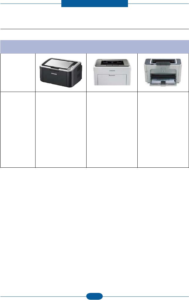
2.1.3 Model Comparison Table
|
Samsung |
Samsung |
HP |
|
ML1660 |
ML2240 |
P1505n |
|
|
|
|
Image
Speed |
16 ppm (A4) |
22 ppm (A4) |
23 ppm (A4) |
|
|
|
|
|
|
processor |
150 MHz |
150 MHz |
266 MHz |
|
|
|
|
|
|
Memory |
8 MB |
8 MB |
32 MB |
|
|
|
|
|
|
Print Language |
GDI |
GDI |
PCL5e |
|
|
|
|
|
|
Input |
150 sheets Bin |
150 sheets Bin |
250 sheets Bin, |
|
10 Manual |
||||
|
|
|
||
|
|
|
|
|
Duplex |
Manual |
Manual |
Manual |
|
|
|
|
|
|
Interface |
USB 2.0 |
USB 2.0 |
USB 2.0 |
|
|
|
|
|
|
Size (mm) |
341 x 224 x 184 mm |
353 x 298 x 213 mm |
379 x 243 x 225 mm |
|
|
|
|
|
|
Toner |
Standard 0.7K / 1K |
Standard 1.5K |
Standard 2K |
Service Manual |
2-7 |
Samsung Electronics |
|

Product spec and feature
2.2 System Overview
This chapter describes the functions and operating principal of the main component.
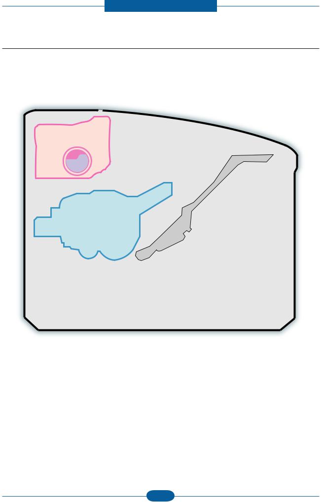
2.2.1 Front View
This illustration may differ from your machine depending on its model.
1 |
Control panel |
5 |
Paper length guide |
2 |
Top cover |
6 |
Paper width guides |
3 |
Toner cartridge |
7 |
Output support |
4 |
Tray |
8 |
Output tray (face down) |
Service Manual |
2-8 |
Samsung Electronics |
|
Product spec and feature
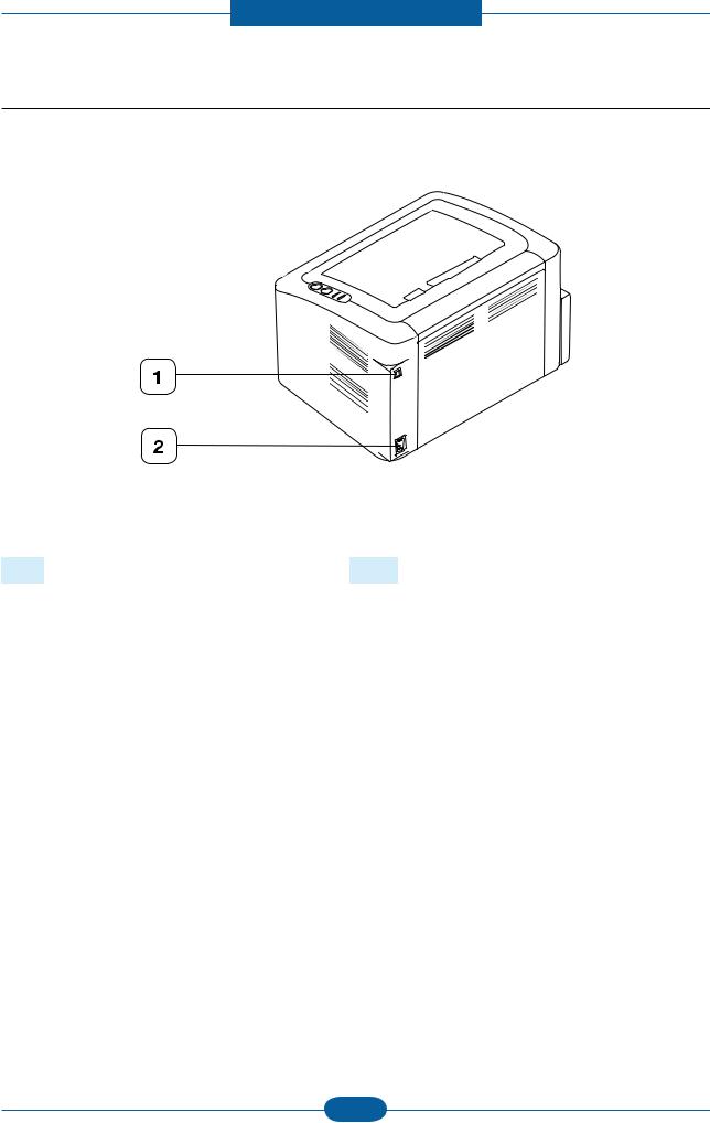
2.2.2 Rear View
This illustration may differ from your machine depending on its model.
1 |
USB port |
2 |
Power receptacle |
Service Manual |
2-9 |
Samsung Electronics |
|
Product spec and feature
2.2.3 System Layout
This model is consisted of the Engine parts and F/W, and said engine parts is consisted of the mechanical parts comprising Frame, Feeding, Developing, Driving, Transferring, Fusing, Cabinet and H/W comprising the main control board, power board, operation panel, PC Interface.
 3
3
14
1
2
6 4
8 |
7 |
|
|
|
9 |
 10
10
11 13
12
NO. NAME
1Pressure roller
2Heat roller
3Exit roller
4Toner Cartridge
5LSU
6Charge roller
7OPC
5
NO. NAME
8Transfer roller
9Deve roller 10 Supply roller
11 Feed roller
12 Friction pad
13 Pickup roller
Service Manual |
2-10 |
Samsung Electronics |
|
Product spec and feature
2.2.3.1 Feeding Part
It is consists of a basic cassette, an MP tray for supplying different types of media (envelope, label, special paper) and parts related to paper transferring.
1) Separation method
Paper is separated by the friction pad mounted to the center of the cassette.
2) Input tray
This model has a bin-type tray.
It takes a center loading method and applies ‘friction pad separating method.’
Both the side guide and the rear guide can be adjusted for for various types of papers from A6 to legal size paper.
It has a paper existence sensing function
(Capacity: 150 sheets (80g/ paper standard), paper arranging function, various size papers accepting function. In the front side, there is a paper level indicator.
3) Pickup roller
It has functions such as a paper pickup function, driving control function, paper feeding function, and removing electronic static function. Pick up roller is drive by solenoid.
Service Manual |
2-11 |
Samsung Electronics |
|
Product spec and feature
2.2.3.2 Transfer Roller
-The transfer roller delivers the toner of the OPC drum to the paper.
-There is no PTLAss’y.
-Life Span : Print over 30,000 sheets (in15~30 )
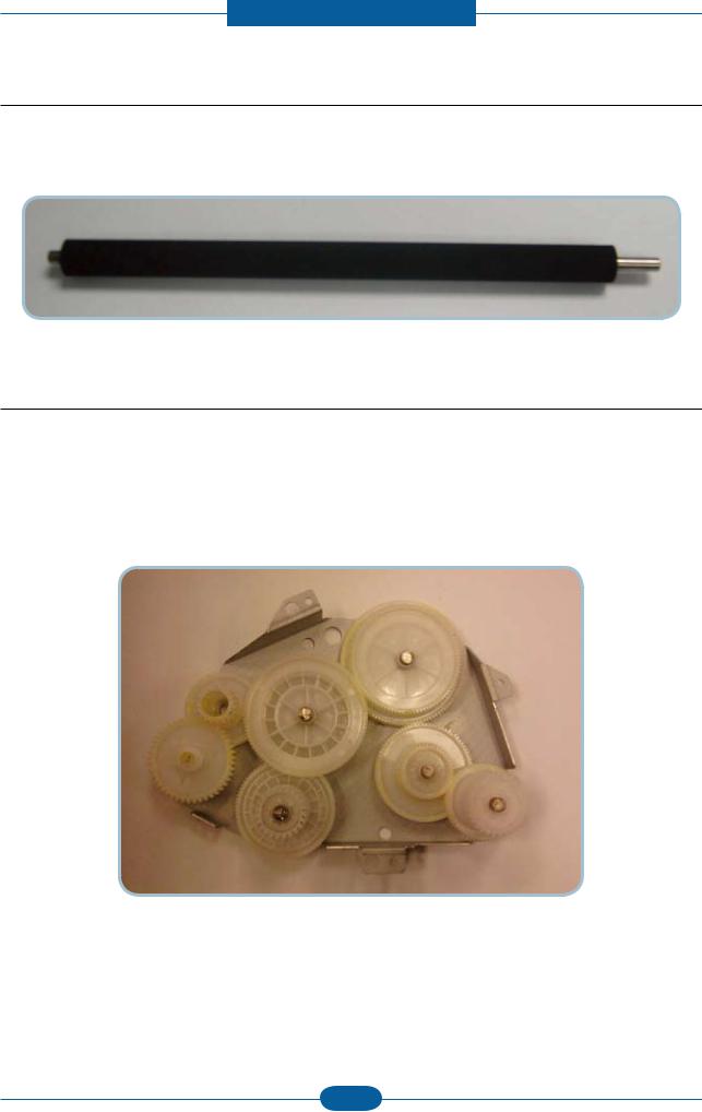
2.2.3.3 Driver Assy
-In ML-1660, the driving device is consisted of OPC, Pickup, Feed, Fuser, GearTrain connected with Mounting member. A step motor for driving is assembled to the left frame.
•Driving Frequency: Step Motor 840 PPS (1050rpm)
•It is a power delivery unit by gearing: Step Motor → Pick-up/Feeder/Transfer/Fuser/Exit
Service Manual |
2-12 |
Samsung Electronics |
|
Product spec and feature
2.2.3.4 Fuser
It is consisted of a halogen lamp, heat roller, pressure roller, thermistor and thermostat. It sticks the toner on a paper by heat and pressure to complete the printing job.
1)Thermostat
When a heat lamp is overheated, a Thermostat cuts off the main power to prevent overheating.
-Thermostat Type : NonContact type dual THERMOSTAT
-Control Temperature : 170 ± 5
2)Thermistor
It is a temperatrue detecting sensor.
-Temperature Resistance : 7 (180 )
3)Heat roller
The heat roller transfers the heat from the lamp to apply a heat on the paper.
The surface of a heat roller is coated with Teflon, so toner does not stick to the surface.
4)Pressure roller
A pressure roller mounted under a heat roller is made of a silicon resin, and the surface also is coated with Teflon. When a paper passes between a heat roller and a pressure roller, toner adheres to the surface of a paper permanently.
5)Halogen Lamp
-Voltage 120 V : 115 ± 5 %
220 V : 230 ± 5 %
- Capacity : 600 Watt ± 25 W
Service Manual |
2-13 |
Samsung Electronics |
|

Product spec and feature
6)Items for safety
Protecting device for overheating
-1st protection device: Hardware cuts off when overheated
-2nd protection device: Software cuts off when overheated
-3rd protection device: Thermostat cuts off main power.
Safety device
-A fuser power is cut off when a front cover is opened
-Maintain a temperature of fuser cover’s surface under 80(C for user, and attach a caution label at where customer can see easily when customer open a rear cover.
Service Manual |
2-14 |
Samsung Electronics |
|
Product spec and feature
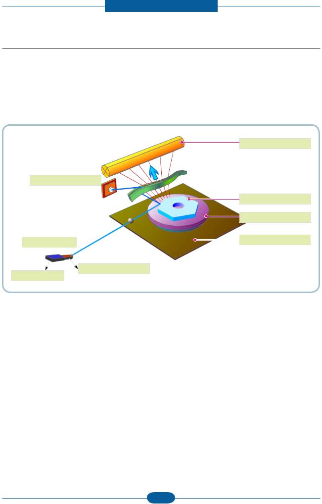
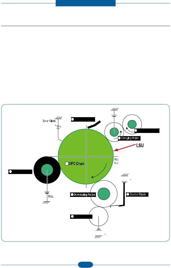
2.2.3.5 LSU (Laser Scanner Unit)
It is the core part of the LBP which switches from the video data received to the controller to the electrostatic latent image on the OPC drum by controlling laser beam, exposing OPC drum, and turning principle of polygon mirror. The OPC drum is turned with the paper feeding speed. The /HSYNC signal is created when the laser beam from LSU reaches the end of the polygon mirror, and the signal is sent to the controller. The controller detects the /HSYNC signal to adjust the vertical line of the image on paper. In other words, after the /HSYNC signal is detected, the image data is sent to the LSU to adjust the left margin on paper. The one side of the polygon mirror is one line for scanning.
OPC Drum
Photo Diode
Polygon Mirror
Polygon Motor
|
|
|
|
Motor Driver |
LD Driver circit |
|
|
|
|
|
|
|||
|
|
|
|
|
LD(Laser Diode)
Protector panel
Service Manual |
2-15 |
Samsung Electronics |
|
Product spec and feature
2.2.3.6 Toner Cartridge
By using the electronic photo process, it creates a visual image. In the toner cartridge, the OPC unit and the developing unit are in a body. The OPC unit has OPC drum and charging roller, and the toner cartridge unit has toner, supply roller, developing roller, and blade (Doctor blade)
•Developing Method : Non magnetic 1 element contacting method
•Toner : Non magnetic 1 element shatter type toner
•Charging capacity : - 39.1 ± 3 μC/g
•Average OD : 8.0 ± 0.5 (Toner)
•The life span of toner (ISO 19752 pattern / A4 standard)
→Initial toner : 0.7K
→Sales toner : 1.5K
•Toner Residual Sensor : Dot count with CRUM(CRU Monitor)
•OPC Cleaning : Collect the toner by using cleaning blade
•Handling of wasted toner : Collect the wasted toner in the cleaning frame by using cleaning blade
•OPC Drum Protecting Shutter : None
•Classifying device for toner cartridge: ID is classified by CRUM.
8 Cleaning Blade
-100V
Max -1.4KV |
|
2 |
Cleaning Roller |
1 |
|
0.20mW
|
-720V |
6 |
-150V↓ |
7 


 -350V
-350V
+3.5kV |
3 |
4 |
|
|
5 


 -550V
-550V
Service Manual |
2-16 |
Samsung Electronics |
|
Product spec and feature
2.2.4 Engine H/W Specifications
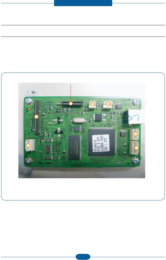
2.2.4.1 Main PBA
The Engine Board and the Controller Board are in one united board, and it is consisted of CPU part and print part in functional aspect. The CPU is functioned as the bus control, I/O handling, drivers, and PC interface. The main board sends the Current Image of Video data to the LSU and manages the conduct of Electrophotography for printing. It is consisted of the circuits of the motor (paper feed, pass) driving, clutch driving, pretransfer lamp driving, current driving.
The signals from the paper feed jam sensor and paper empty sensor are directly inputted to the main board.
CN6, Power I/F |
|
CN4, LSU I/F |
|
CN8, Pick |
|
CN2, Fuser |
|||||
|
|
|
|
|
|
up_clutch |
|
|
|
|
|
|
|
|
|
|
|
|
|
|
|
||
|
|
|
|
|
|
|
|
|
|
|
|
|
|
|
|
|
|
|
|
|
|
|
|
|
|
|
|
|
|
|
|
|
|
|
|
|
|
|
|
|
|
|
|
|
|
|
|
|
|
|
|
|
|
|
|
|
|
|
|
|
|
|
|
|
|
|
|
|
|
|
|
|
|
|
CN7, Main |
|
CN1, Hyper |
|
CN5, Sensor |
||||
motor drive |
|
|
|
|
|
|
|
|
|
|
|
|
|
|
|||
|
|
|
|
|
|
|
|
|
Service Manual |
2-17 |
Samsung Electronics |
|

Product spec and feature
(a) Asic(Jupiter4e)
• CPU Core : Use 32Bit RISC Processor of Jupiter4e, and control system by operating Operation Block of the System Program inside Flash Memory.
-Main Function Block:
Completely Integrated System for Embedded Applications,
32 Bit Risc Architecture, Efficient and Powerful ARM9 CPU
LSU Interface Module for Interfacing PVC with LSU
2 Channel General Purpose DMA Controller for High Speed I/O
Dual Memory Bus Architecture
-Operation Frequency : 150MHz
-Operation Voltage : 3.3V
-POWER ON RESET TIME : 6.6ms below
(b) Memory
1)Flash Memory
Store System Program and can be download System Program through PC Interface
-Capacity : 0.5M Byte
-Access Time : 70 nsec
2)SDRAM
When Printing, use Band Buffer, System Working Memory Area . - 8M capa : 8M Byte basic.
8M :Printing System Working Memory Area - Access Time : 60 nsec
Service Manual |
2-18 |
Samsung Electronics |
|

Product spec and feature
(c) Sensor Input Circuit
■ Paper Empty Sensing
The Paper empty sensor on the tray detects the state of paper empty and the state of paper width i.e. narrow paper width or not.
■ Regi Sensing
N/A
■ Paper Feeding
When paper passes the actuator (feed sensor part), it detects the signal of Photo interrupter, informs the paper feeding state to CPU, and then sprays the image data after certain time.
If it doesn’t detect the feed sensor within 1sec. after paper is fed, paper Jam0 is occurred (LED will be display Orange color).
■ Paper Exit Sensing
N/A
■ Cover Open Sensing
The Cover open sensor is located on the HVPS. After the top cover is opened, +24VS (Solenoid, Main Motor, Polygon motor part of LSU and HVPS), which is supplied to the each unit, is cut off.
In case, the red will be ON for informing the facts to user.
■ SOLENOID Driving
Clutches are driven by turning on TRs, which is controlled by CPU. The diode in the Clutch driving circuits protects TR driven from the noise pulse, which is occurred when the solenoid is de-energized.
■ Motor Driving
The main motor driving circuits is on the main board
There is motor driver IC on the main board control the step motor.
Service Manual |
2-19 |
Samsung Electronics |
|
Product spec and feature
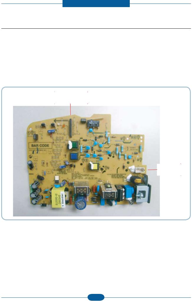
2.2.4.2 HVPS and SMPS Board
The HVPS Board and SMPS Board are in one united board.
The HVPS board creates the high voltage of THV/MHV/Supply/Dev and supplies it to the developer part for making best condition to display the image. The HVPS part takes the 24V and outputs the high voltage for THV/MHV/BIAS, and the outputted high voltage is supplied to the toner, OPC cartridge, and transfer roller
It is the power source of entire system. It is assembled by an independent module, so it is possible to use for common use. It is mounted at the side of the set.
It is consisted of the SMPS part, which supplies the DC power for driving the system, and the AC heater control part, which supplies the power to fuser. SMPS has two output channels. Which are +3.3V and +24V.
Main board
Fuser
Service Manual |
2-20 |
Samsung Electronics |
|
Loading...