


LTS180
GB |
18 VOLT WET / DRY TILE SAW |
USER’S MANUAL |
1 |
FR |
SCIE COUPE-CARRELAGE À EAU / À SEC 18 VOLT |
MANUEL D’UTILISATION |
6 |
DE |
18 VOLT NASS / TROCKEN FLIESENSCHNEIDER |
BEDIENUNGSANLEITUNG |
12 |
ES |
SIERRA HÚMEDA/SECA DE 18 VOLT PARA AZULEJOS |
MANUAL DE UTILIZACIÓN |
18 |
GB ORIGINAL INSTRUCTIONS |
FR TRADUCTION DES INSTRUCTIONS ORIGINALES |
DE ÜBERSETZUNG DER ORIGINALANLEITUNG ES TRADUCCIÓN |
|||
DE LAS INSTRUCCIONES ORIGINALES IT TRADUZIONE DELLE ISTRUZIONI ORIGINALI |
NL VERTALING VAN DE ORIGINELE INSTRUCTIES PT TRADUÇÃO |
||||
DAS INSTRUÇÕES ORIGINAIS |
DK OVERSÆTTELSE AF DE ORIGINALE INSTRUKTIONER SE ÖVERSÄTTNING AV DE URSPRUNGLIGA INSTRUKTIONERNA |
||||
FI ALKUPERÄISTEN OHJEIDEN SUOMENNOS NO OVERSETTELSE AV DE ORIGINALE INSTRUKSJONENE |
RU ПЕРЕВОД ОРИГИНАЛЬНЫХ ИНСТРУКЦИЙ |
PL TŁUMACZENIE |
|||
INSTRUKCJI ORYGINALNEJ |
CZ PŘEKLAD ORIGINÁLNÍCH POKYNŮ HU AZ EREDETI ÚTMUTATÓ FORDÍTÁSA |
RO TRADUCEREA INSTRUCŢIUNILOR ORIGINALE |
LV TULKOTS NO |
||
ORIĢINĀLĀS INSTRUKCIJAS |
LT ORIGINALIŲ INSTRUKCIJŲ VERTIMAS EE ORIGINAALJUHENDI TÕLGE HR PRIJEVOD ORIGINALNIH UPUTA SI PREVOD ORIGINALNIH NAVODIL |
||||
SK PREKLAD POKYNOV V ORIGINÁLI GR μΕΤΑΦΡΑΣΗ ΤΩΝ ΠΡΩΤΟΤΥΠΩΝ ΟΔΗΓΙΩΝ TR ORIJINAL TALIMATLARIN TERCÜMESI

10
1
14
2
3 |
9 |


 8 4
8 4 


5
7
 6
6
13
12
11


 10
10
9
8
Fig. 2
2
16
15
17
18
Fig. 1 |
Fig. 3 |
14
1
13
Fig. 4 |
Fig. 5 |
|
1
19
Fig. 6 |
Fig. 8 |
|
|
|
20 |
|
11 |
|
|
|
|
7 |
|
|
|
|
|
|
|
|
|
Fig. 7 |
|
Fig. 9 |
||

Important! |
It is essential that you read the instructions in this manual before operating this machine. |
Attention ! |
Il est indispensable que vous lisiez les instructions contenues dans ce manuel avant la mise en service |
|
de l’appareil. |
Achtung! |
Bitte lesen Sie unbedingt vor Inbetriebnahme die Hinweise dieser Bedienungsanleitung. |
¡Atención! |
Es imprescindible que lea las instrucciones de este manual antes de la puesta en servicio. |
Attenzione! |
Prima di procedere alla messa in funzione, è indispensabile leggere attentamente le istruzioni contenute |
|
nel manuale. |
Let op ! |
Het is van essentieel belang dat u de instructies in deze gebruiksaanwijzing leest vooraleer u dit toestel |
|
in gebruik neemt. |
Atenção! |
É indispensável que leia as instruções deste manual antes de utilizar a máquina. |
OBS! |
Denne brugsanvisning skal læses igennem inden ibrugtagning. |
Observera! |
Det är nödvändigt att läsa instruktionerna i denna bruksanvisning innan användning. |
Huomio! |
On ehdottoman välttämätöntä lukea tässä käyttöohjeessa annetut ohjeet ennen käyttöönottoa. |
Advarsel! |
Det er meget viktig at du leser denne brukerveiledningen før du tar maskinen i bruk. |
ÇÌËχÌËe! |
иe e‰ Т·У НУИ Л Б‡ФЫТНУП ЛМТЪ ЫПeМЪ‡ МeУ·ıУ‰ЛПУ Ф У˜eТЪ¸ ЛМТЪ ЫНˆЛЛ ЛБ М‡ТЪУfl˘e„У |
|
ÛÍÓ‚Ó‰ÒÚ‚‡. |
Uwaga! |
Przed przystąpieniem do użytkowania tego urządzenia, należy koniecznie zapoznać się z zaleceniami |
|
zawartymi w niniejszym podręczniku. |
Důležité upozornění! |
Nepoužívejte tento přístroj dříve, než si přečtete pokyny uvedené v tomto návodu. |
Figyelem! |
Feltétlenül fontos, hogy a jelen használati útmutatóban foglalt előírásokat az üzembe helyezés előtt |
|
elolvassa! |
Atenţie! |
Este esenţial să citiţi instrucţiunile din acest manual înainte de operarea acestui aparat. |
Uzmanību! |
Svarīgi, lai jūs pirms mašīnas darbināšanas izlasītu instrukcijas šajā rokasgrāmatā. |
Dėmesio! |
Prieš pradėdami eksploatuoti šį prietaisą, svarbu, kad perskaitytumėte šiose instrukcijose pateiktus |
|
nurodymus. |
Tähtis! |
Enne trelli kasutama hakkamist tuleb käesolevas juhendis esitatud juhised kindlasti läbi lugeda. |
Upozorenje! |
Neophodno je da pročitate ove upute prije uporabe ovog uređaja. |
Pomembno! |
Pred uporabo tega stroja, obvezno preberite navodila iz tega priročnika. |
Dôležité! |
Pre prácou s týmto zariadením je dôležité, by ste si prečítali pokyny v tomto návode. |
Προσοχή! |
Είναι απαραίτητο να διαβάσετε τις συστάσεις των οδηγιών αυτών πριν και τη θέση σε |
Dikkat! |
λειτουργία. |
Cihazın çalıştırılmasından önce bu kılavuzda bulunan talimatları okumanız zorunludur. |
Subject to technical modifications / Sous réserve de modifications techniques /Technische Änderungen vorbehalten / Sujeto a modificaciones técnicas / Con riserva di eventuali modifiche tecniche /Technische wijzigingen voorbehouden / Com reserva de modificações técnicas / Med forbehold for tekniske ændringer / Med förbehåll för tekniska ändringar / Tekniset muutokset varataan / Med forbehold om tekniske endringer / åÓ„ÛÚ ·˚Ú¸ ‚ÌeÒeÌ˚ ÚeıÌ˘eÒÍËe ËÁÏeÌeÌËfl / Z zastrzeżeniem modyfikacji technicznych / Změny technických údajů vyhrazeny / A műszaki módosítás jogát fenntartjuk /
Sub rezerva modificaţiilor tehnice / Paturam tiesības mainīt tehniskos raksturlielumus / Pasiliekant teisę daryti techninius pakeitimus / Tehnilised muudatused võimalikud /Podloæno tehniËkim promjenama /Tehnične spremembe dopuščene/
Technické zmeny vyhradené / Υπό την επιφύλαξη τεχνικών τροποποιήσεων / Teknik değişiklik hakkı saklıdır

GB FR DE ES IT NL PT DK SE FI NO RU PL CZ HU RO LV LT EE HR SI SK GR TR
English
SPECIFIC SAFETY RULES
DANGER! Keep hands away from cutting area and the blade. Keep your second hand on auxiliary handle, or motor housing. If both hands are holding the saw, they cannot be cut by the blade.
Do not reach underneath the workpiece. The guard cannot protect you from the blade below the workpiece.
Adjust the cutting depth to the thickness of the workpiece. Less than a full tooth of the blade teeth should be visible below the workpiece.
Never hold piece being cut in your hands or across your leg. Secure the workpiece to a stable platform.
It is important to support the work properly to minimize body exposure, blade binding, or loss of control.
Hold power tool by insulated gripping surfaces when performing an operation where the cutting tool may contact hidden wiring or its own cord.
Contact with a "live" wire will also make exposed metal parts of the power tool "live" and shock the operator.
When ripping always use a rip fence or straight edge guide. This improves the accuracy of cut and reduces the chance of blade binding.
Always use blades with correct size and shape (diamond versus round) of arbour holes. Blades that do not match the mounting hardware of the saw will run eccentrically, causing loss of control.
Never use damaged or incorrect blade washers or bolts. The blade washers and bolt were specially designed for your saw, for optimum performance and safety of operation.
Causes and operator prevention of kickback:
•kickback is a sudden reaction to a pinched, bound or misaligned saw blade, causing an uncontrolled saw to lift up and out of the workpiece toward the operator;
•when the blade is pinched or bound tightly by the kerf closing down, the blade stalls and the motor reaction drives the unit rapidly back toward the operator;
•If the blade becomes twisted or misaligned in the cut, the teeth at the back edge of the blade can dig into the top surface of the wood causing the blade to climb out of the kerf and jump back toward the operator.
Kickback is the result of saw misuse and/or incorrect operating procedures or conditions and can be avoided by taking proper precautions as given below.
Maintain a firm grip with both hands on the saw and position your arms to resist kickback forces. Position your body to either side of the blade, but
not in line with the blade. Kickback could cause the saw to jump backwards, but kickback forces can be controlled by the operator, if proper precautions are taken.
When blade is binding, or when interrupting a cut for any reason, release the trigger and hold the saw motionless in the material until the blade comes to a complete stop. Never attempt to remove the saw from the work or pull the saw backward while the blade is in motion or kickback may occur.
Investigate and take corrective actions to eliminate the cause of blade binding.
When restarting a saw in the workpiece, centre the saw blade in the kerf and check that saw teeth are not engaged into the material. If saw blade is binding, it may walk up or kickback from the workpiece as the saw is restarted.
Support large panels to minimize the risk of blade pinching and kickback. Large panels tend to sag under their own weight. Supports must be placed under the panel on both sides, near the line of cut and near the edge of the panel.
Do not use dull or damaged blades. Unsharpened or improperly set blades produce narrow kerf causing excessive friction, blade binding and kickback.
Blade depth and bevel adjusting locking levers must be tight and secure before making cut. If blade adjustment shifts while cutting, it may cause binding and kickback.
Use extra caution when making a "plunge cut" into existing walls or other blind areas. The protruding blade may cut objects that can cause kickback.
Check lower guard for proper closing before each use. Do not operate the saw if lower guard does not move freely and close instantly. Never clamp or tie the lower guard into the open position. If saw is accidentally dropped, lower guard may be bent. Raise the lower guard with the retracting handle and make sure it moves freely and does not touch the blade or any other part, in all angles and depths of cut.
C heck the operation of the lower guard spring. If the guard and the spring are not operating properly, they must be serviced before use. Lower guard may operate sluggishly due to damaged parts, gummy deposits, or a build-up of debris.
Lower guard should be retracted manually only for special cuts such as "plunge cuts" and "compound cuts." Raise lower guard by retracting handle and as soon as blade enters the material, the lower guard must be released. For all other sawing, the lower guard should operate automatically.
1

GB FR DE ES IT NL PT DK SE FI NO RU PL CZ HU RO LV LT EE HR SI SK GR TR
English
SPECIFIC SAFETY RULES
Always observe that the lower guard is covering the blade before placing saw down on bench or floor. An unprotected, coasting blade will cause the saw to walk backwards, cutting whatever is in its path. Be aware of the time it takes for the blade to stop after switch is released.
DESCRIPTION
1.Lock-off button
2.Spindle lock
3.Bevel scale
4.Bevel lock knob
5.Edge guide lock knob
6.Cutting wheel
7.Base
8.Flow adjustment knob
9. Water bottle release button
10.Water bottle
11.Depth lock knob
12.Wheel wrench storage
13.Battery pack (not included)
14.Switch trigger
15.Inner wheel washer
16.Wheel
17.Outer wheel washer
18.Wheel screw
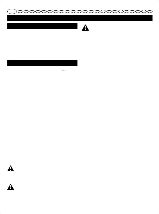
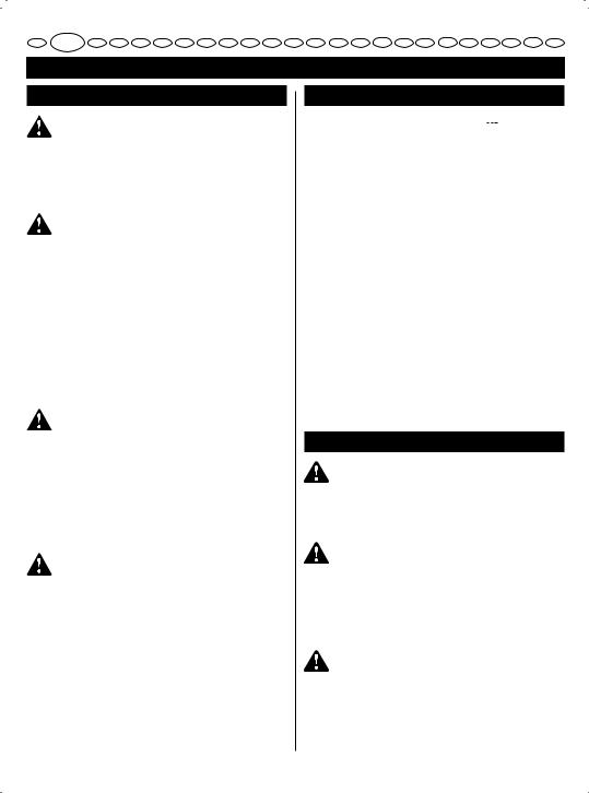
19. Incorrect method of support
20. Correct method of support
ASSEMBLY
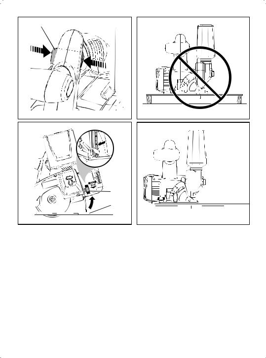
ATTACHING GRAVITY FEED WATER BOTTLE
See Figure 2.
The gravity feed water bottle has a built in air vent that equalizes pressure and allows water to fl ow more freely.
Remove the battery.
Unscrew the nozzle assembly.
Fill water bottle to desired level. Do not overfi ll. Replace nozzle assembly.
Hold water bottle so that nozzle faces down.
NOTE: Water will not escape the bottle unless the tip of the nozzle is depressed.
Insert the water bottle as shown. Gently press down on the bottle until it clicks into place.
To remove water bottle, depress the water bottle release button.
NOTE: For dry cutting, leave water bottle installed to prevent dust and debris from clogging the water supply system.
CAUTION
Water bottle is designed for water only. Use of any other fluid may cause damage to the tool.
WARNING
A 101.6 mm wheel is the maximum wheel capacity of the saw. Also, never use a wheel that is too thick to allow outer wheel washer to engage with the flat on the spindle. Larger wheels will come in contact with the wheel guards, while thicker wheels will prevent wheel screw from securing wheel on spindle. Either of these situations could result in a serious accident.
WARNING
Do not use cutting wheels rated less than the no load speed of this tool. Failure to heed this warning could result in personal injury. Do not use wheel with cracks, gaps, or teeth.
WARNING
Do not use toothed or segmented wheels. Use only continuous rimmed diamond wheels suited for masonry materials.
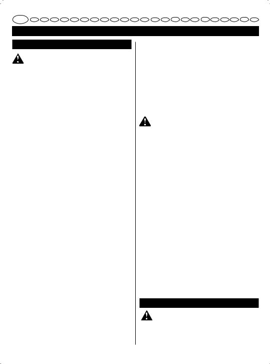
INSTALLING CUTTING WHEEL
See Figure 3.
Remove the battery pack from the saw.
Remove the wheel wrench (5 mm hex key) from the storage area.
Depress the spindle lock button and remove the wheel screw and outer wheel washer.
NOTE: Turn the wheel screw clockwise to remove.
CAUTION
To prevent damage to the spindle or spindle lock, always allow motor to come to a complete stop before engaging spindle lock.
NOTE: Do not run the saw with spindle lock engaged. Wipe a drop of oil onto the inner wheel washer and outer wheel washer where they contact the wheel.
WARNING
If inner wheel washer has been removed, replace it before placing cutting wheel on spindle. Failure to do so could cause an accident since wheel will not tighten properly.
Replace the outer wheel washer.
2
GB FR DE ES IT NL PT DK SE FI NO RU PL CZ HU RO LV LT EE HR SI SK GR TR
English
ASSEMBLY
Depress the spindle lock button, then replace the wheel screw. Tighten the wheel screw securely by turning it counterclockwise.
Return the wheel wrench to the storage area.
NOTE: Never use a cutting wheel that is too thick to allow the outer wheel washer to engage with the fl ats on the spindle.
SPECIFICATIONS
Voltage |
|
18 V |
|
|
|
Wheel Diameter |
|
102 mm |
|||
Wheel Arbor |
|
15.9 mm |
|||
Cutting Depth at 0º |
22.2 mm |
||||
Cutting Depth at 45º |
15.9 mm |
||||
No Load Speed |
|
4,500 min-1 |
|||
Wheel Type |
|
Continuous Rim |
|||
|
|
|
Diamond Wheel |
||
Weight (not incl. battery pack) |
2.6 Kg |
||||
|
|
|
|
||
|
|
BATTERY |
COMPATIBLE |
||
MODEL |
|
PACK |
CHARGER |
||
|
|
(not included) |
(not included) |
||
|
|
|
|
||
|
|
|
BCL-1800 |
||
|
|
BPL-1820 |
BCS618 |
||
|
|
BPL-1815 |
BCL1418 |
||
|
|
BCL1418+ |
|||
|
|
|
|||
|
|
|
BCL1418+ |
||
LTS180 |
|
BPP-1815 |
BCA-180 |
||
|
BC-1815S |
||||
|
|
BPP-1815M |
BC-1800 |
||
|
|
BPP-1817 |
BCL-1800 |
||
|
|
BCS618 |
|||
|
|
BPP-1817M |
BCL1418 |
||
|
|
|
BCL1418+ |
||
|
|
|
BCL1418+ |
||
|
|
|
|
|
|
OPERATION |
|
|
|
|
|
|
|
|
|
|
|
WARNING
Always wear a dust mask when operating tile saws. Failure to do so could result in serious injury.
WARNING
Always wear safety goggles or safety glasses with side shields when operating products. Failure to do so could result in objects being thrown into your eyes, resulting in possible serious injury.
WARNING
Do not use any attachments or accessories not recommended by the manufacturer of this product. The use of attachments or accessories not recommended can result in serious personal injury.
APPLICATIONS
You may use this product for the purposes listed below: Wet cross cutting, rip cutting, and bevel cutting
of man-made tile, pavers, and natural stone tile materials.
For dry cutting of the above materials, a special cutting wheel is required (not provided).
This product will accept Ryobi One+ 18V lithium-ion battery packs and Ryobi One+ 18V nickel-cadmium battery packs.
For complete charging instructions, refer to the Operator’s Manuals for your Ryobi One+ battery pack and charger models.
BATTERY PROTECTION FEATURES
RYOBI 18 V lithium-ion batteries are designed with features that protect the lithium-ion cells and maximize battery life. Under some operating conditions, these built-in features may cause the battery and the tool it is powering to act differently from nickel-cadmium batteries.
During some applications, the battery electronics may signal the battery to shut down, and cause the tool to stop running. To reset the battery and tool, release the trigger and resume normal operation.
NOTE: To prevent further shut down of the battery, avoid forcing the tool.
If releasing the trigger does not reset the battery and tool, the battery pack is depleted. If depleted, the battery pack will begin charging when placed on the lithium-ion charger.
INSTALLING THE BATTERY PACK
See Figure 4.
Place the battery pack in the saw. Align the raised rib on the battery pack with the groove inside the saw, then slide the battery pack into the saw.
Make sure the latches on each side of your battery pack snap into place and the battery pack is secured in the saw before beginning operation.
3
GB FR DE ES IT NL PT DK SE FI NO RU PL CZ HU RO LV LT EE HR SI SK GR TR
English
OPERATION
WARNING
Always remove battery pack from your tool when you are assembling parts, making adjustments, cleaning, or when not in use. Removing battery pack will prevent accidental starting that could cause serious personal injury.
REMOVING THE BATTERY PACK
See Figure 4.
Locate the latches on the side of the battery pack and depress them to release the battery pack from the saw.
Remove battery pack from the saw.
CUTTING WHEELS
The best of cutting wheels will not cut effi ciently if they are dull or badly worn. Using a dull wheel will place a heavy load on the saw. Keep extra wheels on hand, so that sharp wheels are always available.
STARTING/STOPPING THE SAW
See Figure 5.
To start the saw:
Depress the lock-off button. Depress the switch trigger.
Always let the wheel reach full speed, then guide the saw into the workpiece.
To stop the saw: Release the switch trigger.
After you release the switch trigger, allow the wheel to come to a complete stop. DO NOT remove the saw from the workpiece while the wheel is moving.
LOCK-OFF BUTTON
See Figure 6.
The lock-off button reduces the possibility of accidental starting. The lock-off button is located on the handle above the switch trigger. The lock-off button must be depressed before you pull the switch trigger. The lock resets each time the trigger is released.
NOTE: You can depress the lock-off button from either the left or right side.
ADJUSTING WHEEL DEPTH
See Figure 7.
Always keep correct wheel depth setting. The correct wheel depth setting for all cuts should not exceed 6.35 mm below the material being cut. More wheel depth will increase the chance of kickback and cause the cut to be rough. For more depth of cut accuracy, a scale is located on the rear bracket.
Loosen the depth adjustment knob. Determine the desired depth of cut.
Locate the depth of cut scale on the rear bracket. Hold the base fl at against the workpiece and raise or lower the saw until the indicator mark on bracket aligns with the notch on the wheel guard.
Tighten the depth adjustment knob securely.
OPERATING THE SAW
See Figure 8 - 9.
It is important to understand the correct method for operating the saw. Refer to the fi gures in this section to learn the correct and incorrect ways for handling the saw.
WARNING
When lifting the saw from the workpiece, the wheel is exposed on the underside of the saw.
To make the best possible cut:
Hold the saw firmly with both hands.
Avoid placing your hand on the workpiece while making a cut.
Support the workpiece so that the cut (kerf) is always to your side.
Support the workpiece near the cut.
Clamp the workpiece securely so that the workpiece will not move during the cut.
Always place the saw on the workpiece that is supported, not the “cut off” piece.
Place the workpiece with the “good” side down.
Draw a guideline along the desired line of cut before beginning your cut.
MAKING CUTS
Always draw the line to be cut on the tile using a marker or grease pencil. If the tile is shiny and hard-to-mark, place masking tape on the tile and mark the tape.
A common problem when cutting tile is straying from the marked line. Once you’ve strayed from the mark, you can not force the wheel back to the line by twisting the tile. Instead, back up and recut the tile slicing off a small amount of tile until the wheel is back on track.
To avoid this problem, use a straight edge guide whenever possible for making cross cuts and miter cuts.
If wet cutting is desired, it should be performed outside.
MAINTENANCE
WARNING
When servicing, use only identical RYOBI replacement parts. Use of any other parts may create a hazard or cause product damage.
4

GB FR DE ES IT NL PT DK SE FI NO RU PL CZ HU RO LV LT EE HR SI SK GR TR
English
MAINTENANCE
Avoid using solvents when cleaning plastic parts. Most plastics are susceptible to damage from various types of commercial solvents and may be damaged by their use. Use clean cloths to remove dirt, dust, oil, grease, etc.
WARNING
Do not at any time let brake fluids, gasoline, petroleumbased products, penetrating oils, etc., come in contact with plastic parts. Chemicals can damage, weaken or destroy plastic which may result in serious personal injury.
Do not abuse power tools. Abusive practices can damage tool as well as workpiece.
WARNING
Do not attempt to modify this tool or create accessories not recommended for use with this tool. Any such alteration or modification is misuse and could result in a hazardous condition leading to possible serious personal injury.
ENVIRONMENTAL PROTECTION
Recycle raw materials instead of disposing as waste. The machine, accessories and p a ck a g i n g s h o u l d b e s o r t e d fo r environmental-friendly recycling.
SYMBOLS
|
Safety Alert |
V |
Volts |
min-1 |
Revolutions or reciprocations per minute |
|
Direct current |
|
CE Conformity |
|
Please read the instructions carefully before |
|
starting the machine. |
Wear ear protection
Wear eye protection
Recycle unwanted
Waste electrical products should not be disposed of with household waste. Please recycle where facilities exist. Check with your Local Authority or retailer for recycling advice.
5

GB FR DE ES IT NL PT DK SE FI NO RU PL CZ HU RO LV LT EE HR SI SK GR TR
Français
RÈGLES PARTICULIÈRES DE SÉCURITÉ
DANGER ! Eloignez vos mains du disque et de la zone de coupe. Gardez votre deuxième main sur la poignée auxiliaire ou sur le carter moteur. Si vos deux mains maintiennent la scie, elles ne peuvent pas se faire couper par le disque.
Ne tentez pas d’atteindre le dessous de l’élément à couper. Le carter de protection ne peut pas vous protéger du disque qui dépasse de l’élément à couper.
Ajustez la profondeur de coupe à l’épaisseur de l’élément à couper. Il ne doit pas dépasser plus d’une dent entière du disque sous l’élément à couper.
Ne maintenez jamais l’élément à couper dans vos mains ou entre vos jambes. Fixez-le sur un plan de travail stable. Il est important que le travail soit bien supporté pour minimiser les risques de blessures, de blocage du disque et de perte de contrôle.
Maintenez l’outil électrique par ses surface de préhension isolées lorsque vous effectuez des opérations susceptibles de faire entrer en contact l’accessoire de coupe avec des câbles cachés ou avec le propre câble d’alimentation de l’outil. Le contact avec un fi l “sous tension” pourrait véhiculer cette tension électrique vers les parties métalliques de l’outil et exposer l’opérateur à un choc électrique.
Lorsque vos effectuez une coupe longitudinale, utilisez toujours le guide latéral ou le guide de coupe. La précision de la coupe en sera améliorée et le disque aura moins de chances d’être tordu.
Utilisez toujours des disques dont la forme de l’ouverture centrale (en forme de diamant contrairement à ronde) correspond à la broche.
Les disques qui ne correspondent pas au système de fi xation de l’outil tourneront de façon excentrée et entraîneront une perte de contrôle.
N’utilisez jamais des boulons ou rondelles de disque qui seraient endommagés. Les rondelles et le boulon du disque ont été spécialement conçus pour votre scie, afi n de procurer des performances et une sécurité optimales.
Causes et prévention du rebond:
•le rebond est une réaction soudaine au pincement, au blocage ou au mauvais alignement d’un disque, qui entraîne, s’il n’est pas contrôlé, un soulèvement de la scie par rapport à l’élément à couper en direction de l’opérateur;
•lorsque le disque est fortement pincé ou coincé dans le trait de coupe qui se resserre, il se bloque et la réaction du moteur projette rapidement l’appareil vers l’arrière en direction de l’opérateur;
•si le disque se coince ou perd son alignement avec la coupe, les dents situées à l’arrière du disque peuvent mordre dans la face supérieure de l’élément à couper et entraîner un rebond de la scie vers l’opérateur.
Le rebond est le résultat d’une utilisation incorrecte de la scie et/ou de mauvaises procédures ou conditions d’utilisation, et il peut être évité en prenant les précautions indiquées ci-dessous.
Maintenez fermement la scie des deux mains et positionnez vos bras de façon à pouvoir résister aux forces de rebond. Positionnez votre corps d’un côté ou de l’autre du disque de coupe, et non dans son alignement. Le rebond peut entraîner un saut de la scie vers l’arrière, mais les forces de rebond peuvent être contrôlées par l’opérateur si des précautions appropriées sont prises.
Lorsque le disque se bloque, ou lorsque vous interrompez la coupe pour une raison quelconque, relâchez l’interrupteur et maintenez la scie immobile dans le matériau jusqu’à ce que la lame s’arrête complètement. Ne tentez jamais d’enlever la scie de l’élément à couper ou de la faire reculer tant que le disque continue de tourner, sous peine de provoquer un rebond. Examinez le travail et effectuez les corrections adéquates pour éliminer la cause du blocage du disque.
Lorsque vous redémarrez la scie dans l’élément à couper, centrez le disque dans le trait de coupe et vérifiez que ses dents ne mordent pas dans le matériau. Si le disque se coince, il est susceptible d’être entraîné ou de rebondir par rapport à l’élément à couper au moment du redémarrage.
Supportez les grands carreaux pour minimiser les risques de pincement et de rebond. Les grands carreaux ont tendance à s’affaisser sous leur propre poids. Supportez les carreaux des deux côtés, à proximité du trait de coupe et près du bord du carreau.
N’utilisez pas de disques émoussés ou endommagés. Des disques émoussés ou endommagés produisent des traits de coupe étroits, ce qui entraîne un frottement excessif, un coincement du disque et un rebond.
Les leviers de verrouillage des réglages de profondeur et d’angle de coupe de la lame doivent être bien serrés avant de commencer la coupe. Si les réglages changent pendant la coupe, un blocage du disque et un rebond peuvent se produire.
Soyez particulièrement attentif lorsque vous effectuez une «coupe en plongée» dans des murs existants ou autres zones aveugles. La partie du disque qui dépasse peut couper des éléments et provoquer un rebond.
6
GB FR DE ES IT NL PT DK SE FI NO RU PL CZ HU RO LV LT EE HR SI SK GR TR
Français
RÈGLES PARTICULIÈRES DE SÉCURITÉ
Vérifiez que le carter inférieur de protection se referme bien avant chaque utilisation. N’utilisez pas la scie si le mouvement de la protection inférieure n’est pas libre et si elle ne se referme pas instantanément. Ne bloquez jamais la protection inférieure en position ouverte. Si la scie chute de façon accidentelle, la protection inférieure peut s’en trouver tordue. Soulevez la protection inférieure à l’aide de sa poignée de rétractation et assurez-vous qu’elle fonctionne librement et qu’elle ne touche pas le disque ni aucun autre élément, à tous les angles et toutes les profondeurs de coupe.
Vérifiez le fonctionnement du ressort de rappel de la protection inférieure. Si la protection ainsi que son ressort ne fonctionnement pas correctement, ils doivent être réparés avant utilisation. La protection inférieure peut fonctionner de façon lente si des éléments sont endommagés, en cas de dépôts gommeux, ou en cas d’accumulation de débris.
Le carter de protection inférieur ne doit être rétracté à la main que pour des coupes spéciales telles que les «coupes plongeantes» et les «coupes combinées». Soulevez le carter de protection inférieur à l’aide de sa poignée de rétractation dès que le disque pénètre dans le matériau, la protection devant être soulevée. Pour toutes les autres coupes, le carter de protection doit toujours fonctionner automatiquement.
Vérifiez toujours que le carter de protection inférieur recouvre le disque de coupe avant de poser la scie sur un plan de travail ou sur le sol. Un disque non protégé et toujours en rotation fera se déplacer la scie vers l’arrière, et coupera tout ce qui se trouvera sur son chemin. Soyez conscient du temps nécessaire à l’arrêt du disque une fois l’interrupteur relâché.
DESCRIPTION
1.Bouton de verrouillage
2.Blocage de broche
3.Echelle d’inclinaison
4.Bouton de blocage de l’angle de coupe
5.Bouton de verrouillage du guide
6.Disque de coupe
7.Semelle
8.Bouton de réglage de l’écoulement
9. Bouton de déverrouillage du réservoir d’eau
10.Réservoir d’eau
11.Bouton de blocage de la profondeur
12.Logement de la clé de disque
13.Pack batterie (non compris)
14.Gâchette-interrupteur
15.Rondelle intérieure de disque
16.Disque
17.Rondelle extérieure de disque
18.Boulon de disque
19. Méthode incorrecte pour supporter le carreau
20. Méthode correcte pour supporter le carreau
MONTAGE
MONTAGE DU RÉSERVOIR D’ALIMENTATION EN EAU PAR GRAVITÉ
Voir Figure 2.
Le réservoir d’alimentation en eau par gravité comporte une mise à l’air libre qui égalise la pression et permet à l’eau se s’écouler plus librement.
Retirez la batterie.
Dévissez l’embout.
Remplissez le réservoir avec de l’eau jusqu’au niveau désiré. Ne le remplissez pas trop.
Remettez l’embout en place.
Maintenez le réservoir de façon que l’embout soit dirigé vers le bas.
NOTE: L’eau ne s’écoulera pas du réservoir tant que l’extrémité de l’embout ne sera pas enfoncée.
Mettez le réservoir en place tel qu’illustré. Appuyez doucement sur le réservoir jusqu’à ce qu’il s’emboîte en place.
Pour retirer le réservoir, appuyez sur le bouton de déverrouillage du réservoir.
NOTE: Lorsque vous coupez à sec, laissez le réservoir d’eau en place pour éviter que la poussière et les débris ne bouchent le système d’alimentation en eau.
ATTENTION
Le réservoir n’est conçu pour contenir de l’eau. L’utilisation de tout autre liquide peut endommager l’outil.
AVERTISSEMENT
Le diamètre maximal de disque que la scie peut utiliser est de 101.6 mm. De plus, n’utilisez jamais de disque trop épais qui empêcherait la rondelle extérieure du disque de s’insérer dans la partie aplatie de l’axe de broche. Les disques de trop grand diamètre entreraient en contact avec les protections, tandis que les disques trop épais empêcheraient le boulon de bien bloquer le disque sur la broche. L’une comme l’autre de ces situations est susceptible de causer des accidents graves.
7
GB FR DE ES IT NL PT DK SE FI NO RU PL CZ HU RO LV LT EE HR SI SK GR TR
Français
MONTAGE
AVERTISSEMENT
N’utilisez pas de disques de coupe dont la vitesse maximale de rotation est inférieure à la vitesse de rotation à vide de l’outil. Le non respect de cet avertissement peut entraîner des blessures. N’utilisez pas de disques fêlés ou comportant des espaces ou des dents.
AVERTISSEMENT
N’utilisez pas de disques segmentés ou à dents. N’utilisez que des disques au diamant à jante lisse prévus pour les travaux de maçonnerie.
MONTAGE DU DISQUE DE COUPE
Voir Figure 3.
Retirez le pack batterie de la scie.
Sortez la clé de montage (clé hexagonale de 5 mm) de son logement.
Enfoncez le bouton de blocage de broche et dévissez le boulon puis retirez la rondelle extérieure du disque.
NOTE: Tournez le boulon dans le sens des aiguilles d’une montre pour le dévisser.
ATTENTION
Pour éviter d’endommager la broche ou le blocage de broche, laissez toujours le moteur s’arrêter complètement avant de bloquer la broche.
NOTE: Ne mettez pas la scie en marche avec le blocage de broche enfoncé.
Déposez une goutte d’huile sur la rondelle intérieure et sur la rondelle extérieure du disque à l’endroit où elles entrent en contact avec le disque.
AVERTISSEMENT
Si la rondelle extérieure a été retirée, remettez-la en place avant de mettre le disque en place sur la broche. Le non respect de cet avertissement peut entraîner un accident car le disque ne serait pas bien serré.
Remettez la rondelle extérieure en place.
Enfoncez le bouton de blocage de broche, puis revissez le boulon de serrage du disque. Serrez fermement le boulon en le tournant dans le sens inverse des aiguilles d’une montre.
Remettez la clé en place dans son logement.
NOTE: N’utilisez jamais de disque de coupe trop large qui empêcherait la rondelle extérieure de s’insérer dans la partie aplatie de l’axe de broche.
CARACTÉRISTIQUES
Tension |
|
18 V |
|
|
||
Diamètre du disque |
102 mm |
|||||
Axe de broche |
|
15.9 mm |
||||
Profondeur de coupe à 0° |
22.2 mm |
|||||
Profondeur de coupe à 45° |
15.9 mm |
|||||
Vitesse à vide |
|
4,500 tr.mn-1 |
||||
Type de disque |
|
A jante lisse |
||||
|
|
|
Au diamant |
|||
Poids (sans pack batterie) |
2.6 Kg |
|||||
|
|
|
|
|
||
MODÈLE |
BATTERIE |
|
CHARGEUR |
|||
(non fournie) |
|
(non fournie) |
||||
|
|
|
||||
|
|
|
|
|
||
|
|
|
|
BCL-1800 |
||
|
|
BPL-1820 |
|
BCS618 |
||
|
|
BPL-1815 |
|
BCL1418 |
||
|
|
|
BCL1418+ |
|||
|
|
|
|
|||
|
|
|
|
BCL1418+ |
||
LTS180 |
|
|
BCA-180 |
|||
BPP-1815 |
|
BC-1815S |
||||
|
|
BPP-1815M |
|
BC-1800 |
||
|
|
|
BCL-1800 |
|||
|
|
BPP-1817 |
|
|||
|
|
|
BCS618 |
|||
|
|
BPP-1817M |
|
BCL1418 |
||
|
|
|
|
BCL1418+ |
||
|
|
|
|
BCL1418+ |
||
UTILISATION
AVERTISSEMENT
Portez toujours un masque anti-poussières lorsque vous coupez du carrelage. Si vous ne le faites pas vous pouvez subir de graves blessures.
AVERTISSEMENT
Portez toujours des lunettes de sécurité ou des lunettes de protection équipées de volets latéraux lorsque vous coupez des matériaux.
Dans le cas contraire, des objets pourraient être projetés vers vos yeux et provoquer de graves blessures.
AVERTISSEMENT
N’utilisez pas d’accessoires non recommandés par le fabricant de ce produit. L’utilisation d’accessoires non recommandés peut entraîner de graves blessures.
8
 Loading...