


ELT 738 - ELT 1040
|
ELECTRIC BRUSH CUTTER |
ELEKTRISCH ONTGINNINGSMAAIER |
|
OPERATOR’S MANUAL |
GEBRUIKSHANDLEIDING |
|
DÉBROUSSAILLEUSE ELECTRIQUE |
ELEKTRISK BØRSTEBESKÆRER |
|
MANUEL D’UTILISATION |
BRUGERVEJLEDNING |
|
ELEKTRISCH FREISCHNEIDER |
ELEKTRISK RÖJMOTORSÅG |
|
GEBRAUCHSANLEITUNG |
BRUKSANVISNING |
|
DECESPUGLIATORE ELETTRICO |
ELEKTRISK BUSKKLIPPER |
|
||
|
MANUALE D’ISTRUZIONI PER L’USO |
EIERENS HÅNDBOK |
|
||
|
DESBROZADORA ELÉCTRICA |
PENSAIKKOAURA |
|
MANUEL DE ISTRUCCIONES |
KÄYTTÖOHJE |
|
APARADOR DE RELVA ELÉCTRICO |
ЗЛЕКФСПКЙНЗФП ИБМНПКПРФЙКП |
|
MANUAL DE INSTRUÇÕES |
ЕГЧЕЙСЙДЙП ПДЗГЙЩН ЧСЗУЗУ |
|
|
|
ELT 738 - ELT 1040
1 |
|
5 |
|
|
|
2 |
|
6 |
|
|
|
3 |
|
7 |
|
|
|
4 |
|
8 |
|
|
|
2

ELT 738 - ELT 1040
9 |
14 |
|
|
10
15
11
16
12
17
13
3
ELT 738 - ELT 1040
SAFETY WARNINGS
•Read the instructions carefully. Be familiar with the controls and proper use of the unit.
•Children and adolescents must not manipulate unit, except for adolescents in training and under the supervision of a specialist.
•Keep all bystanders at least 5 m away from the unit during operation.
•Before starting, make sure that the cutting head is not in contact with anything, such as a branch, stone.
•Use the unit only in daylight or good artificial light.
•Be aware of the risk of injury ta the head, hands and feet.
•When working with the unit, always wear sturdy, rubber-soled footwear and body protection appropriate to operation of the unit.
•When working with the unit, use the safety attachments supplied.
•Before starting, adjust the handle to your size.
•Do not overreach. Keep proper footing and balance at all times.
•All interventions, whether for maintenance, repair or for changing cutting head or safety attachments, must be undertaken with the motor stopped.
•Frequently inspect the condition of the cutting head, All damaged parts must immediately be replaced.
•Follow all the required precautions when undertaking replacement.
•Use only replacement parts recommended by the manufacturer.
•All guards must be installed properly before operating the unit.
•Caution-Danger! Cutting head is still running.
•Keep unit clean of vegetation and other materials.
•Keep connecting wires away from the tools.
•Turn off the unit and pull the main plug before set-up or cleaning of the unit, and before testing for tangled or damaged wires.
•The connecting wires must be inspected regularly for signs of damage or age.
•The unit must not be used if the connecting wires are not in perfect condition.
•Maintenance/servicing and cleaning of the unit or adjustments to cutting height or work height may only be performed when the motor is off/still and the main plug is disconnected.
•Cord Sets - Make sure your cord set is in good condition. When using a cord set, be sure to use a cord that is heavy enough to carry the current that your unit wilI draw. An undersized cord set will cause a drop in line voltage resulting in power and overheating.
•The table (below) shows the correct size to use depending on the cord length and nameplate amperage rating. If in doubt, use the next heavier size Iine gauge. The smaller the gauge number, the heavier the cord.
MINIMUM WIRE SIZE FOR EXTENSION CORDS FOR 23OV APPLIANCES USING 0-6 AMPS
Cord length (m) |
7 |
15 |
30 |
45 |
|
||||
|
|
|
|
|
|
|
|
|
|
Wire size (mm2) |
1,2 |
1,6 |
1,6 |
2,0 |
|
||||
|
|
|
|
|
|
|
|
|
|
|
|
|
|
|
|
|
|
|
|
|
|
|
|
|
|
|
|
|
|
|
|
|
|
|
|
|
|
|
|
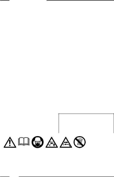
Attention! |
|
|
|
|
|
|
|
|
|
|
|
Observe the |
Read |
Wear head, |
|
following |
operator’s |
eye and ear |
|
safety |
manual. |
protection. |
|
warnings. |
|
|
|
|
|
|
|
|
|
|
If the electric |
|
|
|
|
Keep |
|
|
|
||||
cord is |
|
|
|
||||
bystanders at |
|
|
|
||||
damaged |
Do not |
Ignition/ |
Ignition/ |
||||
least 15 m |
|||||||
remove plug |
operate unit |
Power Switch |
Power Switch |
||||
away from |
|||||||
from socket |
in rain. |
On/Start/Run |
off or stop. |
||||
unit during |
|||||||
and replace |
|
|
|
||||
operation. |
|
|
|
||||
it. |
|
|
|
||||
|
|
|
|
|
|
||
|
|
|
|
|
|
|
|
4
ENGLISH
ASSEMBLY INSTRUCTIONS
D-HANDLE
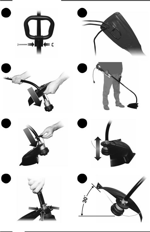
1.Push the D-handle down onto the boom (Fig. 1).
2.Install and tighten the bolt, washer, and wing nut.
STRING GUARD
1.Place the string guard onto the boom above the clamp assembly (Fig. 2).
2.Fit the safety protection onto the bar above the coupling joint in the direction of the motor (fig. 3)
3.See fig. 4 for putting the safety protection extension into position.
OPERATING INSTRUCTIONS
CONNECTING THE CORD
To prevent disconnection when you connect the extension cord to the power cord, use the cord hook (Fig. 5), or tie the cords in a knot.
STARTING / STOPPING
1.Press control switch to switch on the appliance, release to switch off.
HOLDING THE TRIMMER
1. Hold the trimmer as shown (Fig. 6).
ADJUSTING LINE LENGTH
The trimmer has a bump (cutting) head, which releases more trimming line without stopping the motor.
1.When the cord starts to get a bit short, knock the cutting head on the bare ground or on hard ground to make the appliance work at top speed. Repeat the process as often as necessary (Fig. 7).
DECORATIVE TRIMMING
Use a 30-degree angle to remove all vegetation around trees, posts, fences (Fig. 8).
EDGING
When edging, let the tip of the trimming line do the work (fig. 8).
TRIMMING TIPS (Fig. 9)
1.The cutting head will be at the correct angle by holding it parallel to the ground.
2.DO NOT FORCE THE UNIT.
3.Cut to your left for best cutting, and to throw the clippings away from the operator.
4.Move the trimmer slowly in and out of the area being cut, using a forward-backward or side-to-side motion. Maintain top speed for best cutting.
5.Trim only when grass and weeds are dry.
6.The life of your cutting line depends on your trimming techniques, what is being cut, and where the cutting is being done. Some line breakage will occur from:
•Entanglement with foreign matter
•Normal line fatigue
•Attempting to cut thick weeds
•Forcing the line into walls or fenceposts
5

ELT 738 - ELT 1040
MAINTENANCE AND REPAIR INSTRUCTIONS
INSTALLING A NEW TRIMMING LINE
The trimming line may be replaced by two methods - rewinding the existing reel or installing a prewound reel.
Rewinding the Existing Reel
To rewind the existing reel you must:
1.Check for the correct line size.
2.Remove the inner reel and spring.
3.Wind the reel with the new line.
4.Reinstall the existing reel and spring.
The Correct Line to Use
Use a Ø 2,00 mm dual line reel.
Removing the Existing Reel
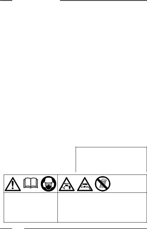
1.Unscrew the Bump Knob counterclockwise (Fig. 10).
2.Remove the inner reel (Fig. 11).
3.Use a clean cloth to clean the inside of the outer spool (Fig.12).
4.Check the indexing teeth on the reel and spool for wear (Fig.13). If necessary, replace the reel and spool.
Winding the Existing Reel
1.Insert the ends of new trimming line into the inner reel holes (Fig.14).
2.Loop the line into two equal lengths before inserting it into the holes.
3.Wind the line, in even and tight layers (Fig.15), onto the reel, and in the direction indicated.
4.Push the ends of the line into the slots (Fig. 16).
Reinstalling the Reel
1.Insert the ends of the line through the eyelets in the outer spool (Fig. 17).
2.Grasp the ends and pull firmly to release the line from the slots in the spool.
3.Install the Bump Knob clockwise (See Fig. 10).
Line installation is now complete.
Installing a prewound reel
1.Use the same instructions as the existing reel:
•The Correct Line to Use;
•Removing the Existing Reel;
•Reinstalling the Reel.
CLEANING / STORAGE
1.Do not block the air vents.
2.Do not use strong detergents on the plastic housing or handle.
3.Moisture can cause a shock hazard. Wipe off moisture with a soft cloth.
4.Clean the unit thoroughly before storing. Hang the unit by the handle loop and store it in a dry, well-ventilated area, out of the reach of children.
6
|
|
|
ENGLISH |
|
|
|
SPECIFICATIONS |
|
|
||
|
|
|
|
||
|
|
|
|
||
MODEL |
ELT 738 |
ELT 1040 |
|
||
Motor |
|
|
|
|
|
Motor |
Electric |
Electric |
|
||
Operating RPM |
7000-8000 g/m |
7500 - 8500 g/m |
|
||
Ignition Switch |
Control switch |
Control switch |
|
||
Drive shaft |
6,2 mm |
6,2 mm |
|
||
Cutting head |
"Bump Head" |
"Bump Head" |
|
||
reel feeding |
reel feeding |
|
|||
|
|
||||
Vibration Level |
1,65 m/s2 (700 W) |
2,15 m/s2 (1000 W) |
|
||
Sound pressure level |
LPAm = 74,6 dB (A) (700 W) |
LPAm = 75,75 dB (A) (1000 W) |
|
||
(no load) |
|
||||
|
|
|
|
|
|
Measured sound power |
LWA = 94,6 dB (A) (700 W) |
LWA = 95,36 dB (A) (1000 W) |
|
||
level (no load) |
|
||||
|
|
|
|
|
|
Guaranteed sound power level |
LWA = 96 dB (A) (700 W) |
LWA = 96 dB (A) (1000 W) |
|
||
|
|||||
(no load) |
|
|
|
|
|
|
|
|
|
||
Cutting path diameter |
370 mm (700 W) |
370 mm (1000 W) |
|
||
Operating weight |
4,9 Kg (700 W) |
5,5 Kg (1000 W) |
|
||
Trimming line diameter |
2,0 mm (700 W) |
2,0 mm (1000 W) |
|
||
|
|
|
|
|
|
TROUBLESHOOTING
PROBLEM |
CAUSE |
ACTION |
||
|
|
|
|
|
• Motor will not start |
1. Motor stops / will not start |
1. |
Check curd to see if it is |
|
|
|
|
|
plugged into an electrical |
|
|
|
|
outlet |
|
2. |
Cutting head bound with |
2. |
Stop motor and clean cutting |
|
|
grass or debris |
|
head |
|
|
|
|
|
• Cutting head will not turn |
1. Flex shaft broken |
1. |
Contact service dealer |
|
when throttle is squeezed |
2. |
Flex shaft not engaged |
2. |
Contact service dealer |
|
||||
|
|
|
|
|
• Cutting head will not advance |
1. Cutting head out of line |
1. |
Refill with new cutting line |
|
line |
2. Inner reel bound up |
2. |
Replace inner reel |
|
|
3. |
Cutting head dirty |
3. |
Clean inner reel and outer |
|
|
|
|
spool |
|
4. |
Indexing teeth worn or |
4. |
Replace inner reel and outer |
|
|
burred |
|
spool |
|
5. |
Line welded |
5. |
Disassemble, remove the |
|
|
|
|
welded section and rewind |
|
|
|
|
the line |
|
6. |
Line twisted when refilled |
6. |
Disassemble and rewind reel |
|
7. |
Nut enough line is exposed |
7. |
Push the Bump Knob and |
|
|
|
|
pull out 102 mm of line until |
|
|
|
|
the line is outside of the |
|
|
|
|
cutting head |
|
|
|
|
|
All information, illustrations and specifications in this manual are based on the latest product information available at the time of printing, We reserve the right to make changes at any time without notice.
7

ELT 738 - ELT 1040
CONSIGNES DE SÉCURITÉ
•Lisez attentivement les instructions. Familiariservous avec les commandes et Ie maniement de l’appareil.
•Les enfants et adolescents ne doivent pas manipuler les appareils, à l’exception des adolescents en formation sous la surveillance d’un spécialiste.
•Les personnes présentés doivent se tenir éloignées de 15 m minimum de l’appareil en fonctionnement.
•Avant de d émarrer l’appareil, vérifier que la tête de coupe n’est pas en contact avec un objet, tel que branche, pierre, etc.
•Utilisez l’appareil uniquement de jour ou avec un bon éclairage artificiel.
•Faites attention aux risques de blessure à la tête aux mains et aux pieds.
•Lorsque vous utilisez l’appareil, vous devez toujours porter des chaussures solides avec des semelles anti-dérapantes et un équipement de protection corporelle approprié.
•Lorsque vous travaillez avec l’appareil, utiliser les dispositifs de protection fournis.
•Avant de commencer à travailler, réglez la poignée à votre taille.
•Ne présumez pas de vos forces. Veillez à prendre des appuis stables à tous moments.
•Les interventions d’entretien et de réparation, ainsi que le changement de la tête de coupe et l’enlèvement dss dispositifs de protection ne doivent être effectués que lorsque le moteur est à l’arrêt.
•Contrôlez fréquemment l’état de la tête de coupe. Toute pièce endom-magée doit être immédiatement remplacée. Suivez toutes les précautions nécessaires lors de ce remplacement.
•N’utiliser que les pièces détachées recommandées par Ie fabricant.
•Vous devez installer correctement toutes les protections avant d’utiliser I’appareil.
•Attention! Danger! La tête de coupe continue à tourner!
•Veillez à ce que l’appareil ne soit pas enco mbré de végétation ou autres matériaux.
•Gardez toujours le cordon d’alimentation et les rallonges à distance des outils de coupe.
•Éteignez l’appareil et débranchez la prise principal0 avant tout ajustage ou nettoyage. • Procédez de même pour tester les cordons enchevêtrés ou abîmés.
•Les cordons doivent être vérifiés régulièrement afin de détecter tout dommage ou usure.
•L’appareil ne doit être utilisé que si les cordons sont en parfaite condition.
•Ne procéder à l’entretien et au nettoyage de l’appareil ou au réglage de la position de coupe que lorsque le moteur est arrêté et que le cordon d’alimentation est débranché.
•Prolongateurs: Assurez-vous qu’ils sont en bon état et d’un calibre suffisant pour transporter le courant nécessaire à l’appareil. Un cordon de taille insuffisante provoquerait une baisse de tension et une surchauffe. Le tableau ci-dessous indique la dimension correcte à utiliser en fonction de la longueur du cordon et du nombre d’ampères. En cas de doute, utilisez un cordon d’un calibre supérieur. Plus le chiffre correspondant au calibrage est petit, plus le cordon est résistant.
SECTION MINIMUM DES PROLONGATEURS POUR DES APPAREILS DE 230 VOLTS UTILISANT DE 0 A 6 AMPERES
Longueur (m) |
7 |
15 |
30 |
45 |
|
||||
|
|
|
|
|
|
|
|
|
|
Section (mm2) |
1,2 |
1,6 |
1,6 |
2,0 |
|
||||
|
|
|
|
|
|
|
|
|
|
|
|
|
|
|
|
|
|
|
|
|
|
|
|
|
|
|
|
|
|
|
|
|
|
|
|
|
|
|
|
|
|
|
|
|
|
|
|
|
|
|
|
|
|
|
|
|
|
|
|
|
|
|
|
|
|
|
|
|
|
|
|
|
|
|
|
|
|
|
|
|
|
|
|
|
|
|
|
|
|
|
|
Les personnes |
|
|
|
|
|||
Attention! |
|
|
Portez des |
présentes |
Si le câble |
|
|
|
|||
|
|
doivent se |
électrique est |
|
|
|
|||||
Observez les |
Lisez le |
lunettes et |
N’utilisez pas |
Interrupteur |
Interrupteur |
||||||
tenir éloignées |
abîmé |
||||||||||
consignes de |
manuel |
des protège- |
de 15 m |
enlevez la |
l’appareil |
marche. On/ |
arrêt. off ou |
||||
sécurité |
d’utilisation. |
oreilles et |
sous la pluie. |
Start/Run. |
stop. |
||||||
minimum de |
fiche et |
||||||||||
suivantes. |
|
|
tête. |
|
|
|
|||||
|
|
l’appareil en |
remplacez-le. |
|
|
|
|||||
|
|
|
|
|
|
|
|||||
|
|
|
|
fonctionnement. |
|
|
|
|
|||
|
|
|
|
|
|
|
|
|
|
|
|
8
FRANÇAIS
INSTRUCTIONS DE MONTAGE
POIGNÉE EN D
1.Faites glisser la poignée en D le long du manche (Fig. 1).
2.Mettez en place l’écrou, le boulon et la rondelle, puis serrez.
CAPOT DE PROTECTION
1.Montez la protection sur la tige audessus du raccord d'accouplement en l'orientant vers le moteur (Fig. 2).
2.Placez la rallonge de protection de la façon illustrée sur la figure 3.
3.Mettez les vis en place à l’aide d’un tournevis Phillips (Fig. 4).
INSTRUCTIONS D’UTILISATION
CONNEXION DU PROLONGATEUR
Afin d’éviter toute déconnexion intem-pestive lorsque vous connectez le prolongateur au cordon d’alimentation, utilisez le fixe-cordon (Fig. 5). Vous pouvez également nouer le prolongateur et le cordon.
DÉMARRAGE / ARRÊT
1.Pour démarrer l'appareil appuyez sur l'interrupteur de commande et lâchez-le pour l'arrêter.
MANIEMENT
1.Tenez le coupe-bordures comme indiqué (Fig. 6).
RÉGLAGE DE LA LONGUEUR DU FIL DE COUPE
Ce coupe-bordure possède un système de coupe à fil, permettant de dérouler le fil de coupe sans arrêter le moteur.
1.Lorsque le câble commence à être court, frappez la tête de coupe directement sur le sol ou sur un terrain dur en faisant fonctionner l'appareil à grande vitesse (fig. 7).
COUPE DÉCORATIVE
Inclinez l’appareil selon un angle de 30° pour retirer toute végétation autour des arbres, des poteaux, des haies etc. (Fig. 8).
BORDURES
Lorsque vous coupez des bordures, laissez l’extrémité du fil effectuer la coupe.
COUPE DES BORDURES (Fig. 9)
1.La tête de coupe se trouvera à un angle correct en étant parallèle au sol.
2.NE FORCEZ PAS L’APPAREIL.
3.Pour effectuer une meilleure coupe et évacuer les débris d’herbe loin de vous, travaillez sur votre gauche.
4.Déplacez le coupe-bordures lentement à l’intérieur et à l’extérieur de la zone de coupe, par un mouvement d’avant en arrière et de gauche à droite. Conservez une vitesse élevée pour une meilleure coupe.
5.Coupez uniquement lorsque le gazon et les herbes sont secs.
6.La durée de vie de votre fil dépend de vos techniques de coupe, de ce que vous coupez, et des endroits où vous effectuez ces coupes. Des ruptures de fil peuvent être causées par:
•des objets s’accrochant au fil;
•une usure normale du fil;
•une tentative de couper des herbes épaisses et robustes;
•un choc contre des murs ou des barrières.
9

ELT 738 - ELT 1040
INSTRUCTIONS D’ENTRETIEN / RÉPARATION
INSTALLATION D’UN NOUVEAU FIL DE COUPE
Vous pouvez remplacer le fil de coupe de deux manières différentes : en enroulant un nouveau fil sur la bobine existante ou en installant une nouvelle bobine de fil.
Utilisation de la bobine existante
Pour utiliser la bobine réceptrice existante, vous devez:
1.Vérifier le diamètre du fil à utiliser.
2.Enlever la bobine réceptrice et le ressort.
3.Enrouler le nouveau fil de coupe sur la bobine réceptrice.
4.Réinstaller la bobine réceptrice et le ressort.
Fil de coupe à utiliser
Utilisez une bobine réceptrice à deux fils avec un fil de coupe de Ø 2,00 mm.
Démontage de la bobine existante
1.Dévissez le bouton de serrage du fil dans le sens inverse des aiguilles d’une montre (Fig.10).
2.Démontez la bobine réceptrice (Fig. 11).
3.A l’aide d’un chiffon propre, nettoyez l’intérieur de la bobine débitrice (Fig. 12).
4.Vérifiez le degré d’usure des dents (Fig.13). Si nécessaire, remplacez les bobines réceptrice et débitrice.
Enroulage du fil
1.Insérez les extrémités du nouveau fil de coupe dans les trous de la bobine réceptrice (Fig.14).
2.Formez une boucle de façon à obtenir deux longueurs égales avant d’insérer le fil dans les trous.
3.Enroulez le fil autour de la bobine en couches régulières et serrées (Fig.15), dans le sens indiqué.
4.Placez les extrémités du fil dans les encoches (Fig. 16).
Réinstallation de la bobine
1.Insérez les extrémités du fil dans les oeillets de la bobine débitrice (Fig. 17).
2.Attrapez les extrémités et tirez fermement, afin de libérer le fil des encoches de la bobine réceptrice.
3.Serrez le bouton de serrage dans le sens des aiguilles d’une montre (voir Fig. 18).
L’installation du fil est maintenant terminée.
Installation d’une nouvelle bobine
1 . Procédez comme pour la bobine réceptrice existante:
•Choix du fil de coupe à utiliser;
•Démontage de la bobine réceptrice existante;
•Réinstallation de la bobine réceptrice.
NETTOYAGE / STOCKAGE
1.N’obstruez pas les filtres à air.
2.N’utilisez pas de détergeants puissants sur les revêtements en plastique ni sur la poignée.
3.L’humidité entraîne des risques de courtscircuits. Essuyez donc bien la machine avec un chiffon doux.
4.Nettoyez soigneusement l’appareil avant de l’entreposer. Accrochez-le par la poignée dans un endroit sec et aéré, hors de portée des enfants.
10
|
|
|
|
|
|
|
FRANÇAIS |
|
|
|
|
SPÈCIFICATIONS |
|
|
|
|
|||
|
|
|
|
|
|
|
|||
|
|
|
|
|
|||||
MOTEUR |
|
ELT 738 |
|
ELT 1040 |
|
||||
MOTEUR |
|
|
|
|
|
|
|
|
|
Moteur |
|
Electrique |
|
Electrique |
|
||||
Régime nominal |
|
7000-8000 g/m |
|
7500 - 8500 g/m |
|
||||
Démarreur |
|
Bouton d’accélération |
|
Bouton d’accélération |
|
||||
Arbre d’entraînement |
|
6,2 mm |
|
6,2 mm |
|
||||
Tête de coupe |
|
Avance du fil de coupe |
|
Avance du fil de coupe |
|
||||
|
"Bump Head" |
|
"Bump Head" |
|
|||||
|
|
|
|
||||||
Niveau de vibration |
|
1,65 m/s2 (700 W) |
|
2,15 m/s2 (1000 W) |
|
||||
Niveau de pression du son |
|
LPAm = 74,6 dB (A) (700 W) |
|
LPAm = 75,75 dB (A) (1000 W) |
|
||||
(sans charge) |
|
|
|
||||||
|
|
|
|
|
|
|
|
|
|
Niveau de puissance du son |
|
LWA = 94,6 dB (A) (700 W) |
|
LWA = 95,36 dB (A) (1000 W) |
|
||||
mesuré (sans charge) |
|
|
|
||||||
|
|
|
|
|
|
|
|
|
|
Niveau de puissance du son à |
LWA = 96 dB (A) (700 W) |
|
LWA = 96 dB (A) (1000 W) |
|
|||||
|
|
||||||||
garantie (sans charge) |
|
|
|
|
|
|
|
|
|
|
|
|
|
|
|
||||
Diamètre trajectoire de coupe |
|
370 mm (700 W) |
|
370 mm (1000 W) |
|
||||
Poids |
|
4,9 Kg (700 W) |
|
5,5 Kg (1000 W) |
|
||||
Diamètre du fil de coupe |
|
2,0 mm (700 W) |
|
2,0 mm (1000 W) |
|
||||
|
|
|
|
|
|
|
|
|
|
|
|
|
DÉPANNAGE |
|
|
|
|
|
|
|
|
|
|
|
|
||||
PROBLÈME |
CAUSE |
ACTION |
|
||||||
|
|
|
|
|
|
|
|
||
• Le moteur ne démarre pas |
1. |
Le moteur s’arrête/ne |
1. |
Vérifiez si le cordon de |
|
||||
|
|
|
démarre pas |
|
|
raccordement est branché |
|
||
|
|
|
|
|
|
|
sur une prise électrique |
|
|
|
2. |
Tête de coupe encombrée |
2. |
Arrêtez le moteur et nettoyez |
|
||||
|
|
|
d’herbe et de débris |
|
|
la tête de coupe |
|
||
|
|
|
|
|
|
|
|
||
• La tête de coupe ne tourne |
1. |
Arbre flexible cassé |
1. |
Contactez votre distributeur |
|
||||
pas lorsque le bouton |
|
|
|
|
|
|
agréé |
|
|
d’accélération est actionné |
2. |
Arbre flexible mal engagé |
2. |
Contactez votre distributeur |
|
||||
|
|
|
|
|
|
|
agréé |
|
|
|
|
|
|
|
|
|
|
||
• La tête de coupe ne fait pas |
1. |
Plus de fil dans la tête de |
1. |
Réinstallez du fil |
|
||||
avancer le fi |
|
|
coupe |
2. |
Remplacez la bobine |
|
|||
|
2. |
Bobine réceptrice bloquée |
|
||||||
|
|
|
|
|
|
|
réceptrice |
|
|
|
3. |
Tête de coupe encrassée |
3. |
Nettoyez la bobine réceptrice |
|
||||
|
|
|
|
|
|
|
et la bobine débitrice |
|
|
|
4. |
Dents usées et |
4. |
Remplacez la bobine |
|
||||
|
|
|
|
|
|
|
réceptrice ébarbées et la |
|
|
|
|
|
|
|
|
|
bobine débitrice |
|
|
|
5. |
Fil noué |
5. |
Demontez la tête, ôtez la partie |
|
||||
|
|
|
Fil tordu lors de son rembobinage |
|
|
nouée et rembobinez le fil |
|
||
|
6. |
6. |
Demontez et rembobinez |
|
|||||
|
7. |
Pas assez de fil à |
7. |
Appuyez sur le bouton de l'extérieur |
|
||||
|
|
|
|
|
|
|
déblocage du fil et tirez 102 mm de |
|
|
|
|
|
|
|
|
|
fil, jusqu'à ce que ce dernier soit |
|
|
|
|
|
|
|
|
|
hors de la tête de coupe |
|
|
Toutes les informations, illustrations et spécifications de ce manuel sont basées sur les dernières informations disponibles au moment où nous les imprimons. Nous nous réservons le droit d’apporter des modifications à tout moment, sans notification préalable.
11
ELT 738 - ELT 1040
GEFAHRENHINWEISE
•Lesen Sie diese Anweisungen sorgfältig durch. Machen Sie sich mit der Bedienung und der Handhabung des Gerätes vertraut.
•Kinder und Jugendliche dürfen Geräte mit metallischen Arbeits-werkzeugen nicht handhaben, ausgenommen sind Jugendliche in der Ausbildung unter Aufsicht eines Fachkundigen.
•Es dürfen sich keine Personen in weniger als 15 m Entfernung von dem Gerät aufhalten, während es in Betrieb ist.
•Vor dem Starten muß darauf geachtet werden, daß der Schneidkopf keine Berührung mit Gegenstanden, z-B. Äste, Steine usw., hat.
•Das Gerät darf nur tagsüber bzw. bei guter künstlicher Beleuchtung eingesetzt werden.
•Seien Sie sich der Verletzungsgefahr von Kopf, Händen und Füßen bewußt.
•Beim Arbeiten mit dem Gerät muß festes Schuhwerk mit griffiger Sohle und sachgemäße Körperschutz-ausrüstung entsprechend dem jeweiligen Verwendungszweck getragen werden.
•Arbeiten Sie nie ohne die vorge-sehenen Schutzvorrichtungen mit dem Gerät.
•Der Griff muß vor Arbeitsbeginn entsprechend der Körpergrösße eingestellt werden.
•Überschätzen Sie sich nicht, Beim Arbeiten ist auf einen sicheren Stand zu achten.
•Wartungsund Reinigungsarbeiten sowie das Auswechseln der Abeits-werkzeuge und das Abnehmen der Schutzeinrichtungen dürfen nur bei stiIlgesetztem Motor vorgenommen werden.
•Der Schneidekopf ist in regelmäßigen kurzen Abständen auf Beschädigung zu prüfen und gegebenenfalls sofort auszutauschen. Beim Auswechseln sind die erforderlichen Vorsichtsmaßnahmen zu treffen.
•Es dorfen nur die vom Hersteller empfohlenen Ersatzteile verwendet werden.
•Alle Schutzeinrichtungen müssen ordnungsgerne
angebracht sein, bevor Sie mit dem Gerät zu arbeiten beginnen.
•Achtung Gefahr! Schneidwerkzeug läuft nach.
•Achten Sie darauf, daß keine Pflanzen oder sonstige Gegenstände im Gerät verfangen sind.
•Halten Sie Stromund Verlängerungs-kabel immer von den Schneide-werkzeugen entfernt.
•Schalten Sie das Gerät ab und ziehen Sie den Stecker aus der Steckdose, bevor Sie das Gerät einstellen oder reinigen und bevor Sie es auf verwiekelte bzw. beschädigte Kabel prüf en.
•Die Kabel müssen regelmäßig geprüft werden, um Beschädigung und Verschleiß mit Sicherheit festzustellen.
•Das Gerät darf nur mit Kabeln in einwandfreiem Zustand benutzt werden.
•Wartungs-und Reinigungsarbeiten am Gerät und das Verstellen der Schnitt-bzw. Arbeitshöhe dürfen nur bei stillgesetztem Motor und gezogenem Netzstecker vorgenommen werden.
•Gehen Sie sicher, dass Ihre Kabel in gutem Zustand sind, und dass Sie ein Kabel verwenden, das stark genug ist für den Strom, den Ihr Gerät abnehmen wird.
•Ein zu kleines Kabel worde einen Spannungsabfall verursachen, der wiederum Überhitzung und Spannungsabfall hervorrufen würde. Die Tabelle zeigt die zu verwendende korrekte Grösse, welche von der Länge des Kabels und der auf dem Namensschil dangegebenen Ampèrezahl abhängt. Im Zweifelsfall benutzen Sie die nächstgrössere Leitungsstärke. Je kleiner die Messzahl, desto stärker das Kabel.
MIN. LEITUNGSQUERSCHNIIT DER
VERLÄNGERUNGSKABEL FÜR DIESES GERÄT
Kabellänge (m) |
7 |
15 |
30 |
45 |
|
||||
|
|
|
|
|
|
|
|
|
|
Querschnitt (mm2) |
1,2 |
1,6 |
1,6 |
2,0 |
|
||||
|
|
|
|
|
|
|
|
|
|
|
|
|
|
|
|
|
|
|
|
|
|
|
|
|
|
|
|
|
|
|
|
|
|
|
|
|
|
|
|
|
|
|
|
|
|
|
|
|
|
|
|
|
|
|
|
|
|
|
|
|
|
|
|
|
|
|
|
|
|
|
|
|
|
|
|
|
|
|
|
|
|
|
|
|
|
|
|
Es dürfen sich |
Bei |
|
|
|
||
Achtung! |
|
|
|
keine Personen |
Beschädigung |
|
|
|
||
|
|
Tragen Sie |
in weniger als |
des |
Verwenden |
Einschalter. |
Ausschalter. |
|||
Beachten Sie |
|
|
||||||||
Lesen Sie die |
Sicherheits- |
15 m |
Elektrokabels |
Sie das Gerät |
||||||
folgende |
Bedienanleitung. |
brille und |
Entfernung von |
den Stecker aus |
nicht im |
On/Start/ |
Off oder |
|||
Sicherheits- |
dem Gerät |
der Steckdose |
Run. |
Stop. |
||||||
hinweise. |
|
|
Gehürschutz. |
aufhaken, |
nehmen und |
Regen. |
|
|
||
|
|
|
|
während es in |
durch einen |
|
|
|
||
|
|
|
|
Betrieb ist. |
neuen ersetzen. |
|
|
|
||
|
|
|
|
|
|
|
|
|
|
|
12

DEUTSCH
EINBAUANWEISUNGEN
HANDGRIFF
1.Lassen Sie den Handgriff den Schaft entlang gleiten (Abb. 1).
2.Plazieren Sie die Schraube, die Scheibe und die Flügelmutter und ziehen Sie sie fest.
SCHUTZKAPPE
1.Den Schutz auf die Stange oberhalb des Verbindungsstückes montieren und auf den Motor richten (Abb. 2).
2.Die Schutzverlängerung wie in Abb. 3 positionieren.
3.Montieren sie die schrauben mit en Schraubendreher (Abb. 4).
BENUTZUNGSANWEISUNGEN
ANSCHLUSSDES VERLÄNGERUNGSKABELS
Verwenden Sie immer den Kabelhalter, wenn Sie das Verlängerungskabel anschließen, um eine ungewollte Trennung sicher zu verhindern (Abb. 5). Sie können auch eine Knotenverbindung zwischen Verlängerungsschnur und Versorgungsschnur herstelle.
EIN- / AUSSCHALTEN
1.Zum Einschalten den Start-Schalter drücken, und zum Abschalten diesen wieder kurz betätigen.
HANDHABUNG
1.Halten Sie den Rasenrandschneider wie abgebildet (Abb. 6).
LÄNGENEINSTELLUNG DES SCHNEIDEDRAHTES
Dieser Rasenrandschneider ist mit einem Bump-Head-System ausgestattet, durch das der Schneidedraht abgewickelt werden kann, ohne den Motor abzusteflen.
1.Wenn der Schneiddraht kurz zu werden droht, den Scherkopf auf nackten Erdboden oder harten Boden schlagen und dabei das Gerät bei großer Geschwindigkeit laufen lassen (Abb. 7).
DEKORATIVER SCHNITT
Neigen Sie den Rasenrandschneider in einem 30°-Winkel, um die Vegetation um die Baume, Pfosten, Schranken usw. herum zu entfernen (Abb. 8).
RASENRAND
Lassen Sie das Ende des Schneidedrahtes am Rasenrand seine Schnittfunktion ausüben.
RASENRANDSCHN ITT (Abb. 9)
1.Der Schneidekopf muß parallel zum Boden gehalten werden.
2.ÜBERBEANSPRUCHEN SIE DAS GERÄT NICHT.
3.Arbeiten Sie nach links, um optimale Schnittergebnisse zu erzielen und das Schnittgut sowie Steine u.ä. vom Bediener weg zu schleudern.
4.Führen Sie den Rasenrandschneider langsam in den Schnittbereich hinein und wieder heraus, indem Sie Vorwärts-/Rückwärtsbewegungen oder seitliche Bewegungen ausführen. Behatten Sie für beste Schnittergebnisse die hohe Geschwindigkeit aufrecht.
5.Schneiden Sie nur Rasen und Gras in trockenem Zustand.
6.Die Lebensdauer Ihres Schneidedrahts ist von Ihrer Schnittechnik, dem Schnittgut und den Stellen, an denen Sie das Gerät einsetzen, abhängig. Drahtbruch kann auf folgenden Ursachen beruhen:
•es haben sich Steine, Äste o.ä. . am Draht verfangen;
•der normale Verschleiß des Drahtes;
•Sie haben versucht, zu dicke Stengel zu schneiden;
•das Gerät ist gegen eine Mauer oder Schranke geprallt.
13

ELT 738 - ELT 1040
WARTUNGSUND REPARATURANWEISUNGEN
EINBAU EINES NEUEN
SCHNEIDEDRAHTES
Sie können den Schneidedraht auf zwei Arten ersetzen: indem Sie einen neuen Draht auf die vorhandene Rolle wickeln oder indem Sie eine neue Drahtrolle einbauen.
Weiterverwendung der vorhandenen Rolle
Gehen Sie folgendermaßen vor:
1.Vergewissern Sie sich hinsichtlich der einzusetzenden Drahtart.
2.Nehmen Sie die Aufwickelrolle und die Feder heraus.
3.Wickeln Sie den neuen Schneidedraht auf die Rolle auf.
4.Setzen Sie Aufwichelrolle und Feder wieder ein.
Zu verwendender Schneidedraht
Nehmen Sie eine Doppeldraht-Auf-wickelrolle mit einem Schneidedraht von Ø 2,00 mm.
Ausbau der vorhandenen Rolle
1.Die Schraube des Festziehknopfes im Gegenuhrzeigersinn los (Abb. 10).
2.Bauen Sie die Aufwickelrolle aus (Abb. 11).
3.Reinigen Sie die Aufwickelrolle mit einem sauberen Lappen (Abb.12).
4.Prüfen Sie den Verschleiß der Zähne (Abb. 13). Falls erforderlich, wechseln Sie die Aufund Abwickel rollen aus.
Aufwickeln des Drahtes
1.Führen Sie die Enden des neuen Schneidrahtes in die Löcher der Aufwickelrolle ein (Abb. 14).
2.Bilden Sie einen Schleife, um zwei gleiche Drahtlängen zu erhalten, bevor Sie den Draht in die Löcher der Spule einführen.
3.Wickeln Sie den Draht gleichmäßig und eng (Abb. 15) in der angegebenen Richtung auf.
4.Führen Sie die Drahtenden in die Schlitze ein (Abb. 16).
Wiedereinbau der Rolle
1.Führen Sie die Drahtenden in die Ösen der Abwickelrolle ein (Abb. 17).
2.Ziehen Sie kräftig an den Drahtenden um den Draht aus der Aussparung der Aufwickelrolle hervorzuziehen.
3.Schrauben Sie den Festziehknopf in Uhrzeigerrichtung wieder fest (Abb. 10).
Der Drahteinbau ist hiermit abgeschlossen.
Einbau Einer Neuen Rolle
1.Gehen Sie wie bei der Wiedewerwendung der vorhandenen Aufwickelrolle vor:
•Wahl d es zu verwendender Schneidedraht;
•Ausbau der vor handenen Aufwickelrolle;
•Wiedereinbau der Aufwickelrolle.
REINIGUNG / AUFBEWAHRUNG
1.Verstopfen Sie die Luftfitter nicht.
2.Verwenden Sie keine scharfen Reinigungsmittel für die Plastikteile und den Griff.
3.Feuchtigkeit birgt Kurzschlußrisiken. Wischen Sie das Gerät gründlich mit einem weichen Lappen ab.
4.Reinigen Sie den Rasenrandschneider sorgfältig, bevor Sie ihn wegräumen. Setzen Sie ihn immer in seine Wandhalterung ein, die sich in einem trockenen und gut belüfteten Raum außerhalb der Reichweite von Kindern befinden muß.
14
|
|
|
DEUTSCH |
|
|
|
SPEZIFIKATIONEN |
|
|
||
|
|
|
|
||
|
|
|
|
||
TYPE |
ELT 738 |
ELT 1040 |
|
||
Motor |
|
|
|
|
|
Betriebsart |
Elektrisch |
Elektrisch |
|
||
Nenndrehzahl |
7000-8000 g/m |
7500 - 8500 g/m |
|
||
Einschalter |
Start-Schalter |
Start-Schalter |
|
||
Antriebswelle |
6,2 mm |
6,2 mm |
|
||
Schneidekopf |
Stoßweiser Drahtvorschub |
Stoßweiser Drahtvorschub |
|
||
Bump-Head-System |
Bump-Head-System |
|
|||
|
|
||||
Vibrationen |
1,65 m/s2 (700 W) |
2,15 m/s2 (1000 W) |
|
||
Schalldruckpegel gem |
LPAm = 74,6 dB (A) (700 W) |
LPAm = 75,75 dB (A) (1000 W) |
|
||
DIN 45 635 Teil 1 (im Leerlauf) |
|
||||
Schallleistungsstufe gemessen |
LWA = 94,6 dB (A) (700 W) |
LWA = 95,36 dB (A) (1000 W) |
|
||
(im Leerlauf) |
|
|
|
|
|
|
|
|
|
|
|
Schallleistungs - Stufe |
LWA = 96 dB (A) (700 W) |
LWA = 96 dB (A) (1000 W) |
|
||
Gewährleistet (im Leerlauf) |
|
||||
|
|
|
|
|
|
|
|
|
|
||
Schnittkreisdurchmesser |
370 mm (700 W) |
370 mm (1000 W) |
|
||
Gewicht |
4,9 Kg (700 W) |
5,5 Kg (1000 W) |
|
||
Schneidedraht-Durchmesser |
2,0 mm (700 W) |
2,0 mm (1000 W) |
|
||
|
|
|
|
|
|
PANNENHILFE
PROBLEM |
URSACHE |
EINGRIFF |
||
|
|
|
|
|
• Der Motor springt nicht an |
1. Motor bleibt stehen / läuft nicht |
1. |
Prüfen Sie, ob das |
|
|
|
an |
|
Anschlußkabel in einer |
|
|
|
|
Steckdose steckt |
|
2. |
Schneidekopf durch Gras oder |
2. |
Motor abschalten und |
|
|
sonstige Gegenstände blockiert |
|
Schneidekopf reinigen |
|
|
|
|
|
• Der Schneidekopf dreht sich |
1. Flexible Welle gebrochen |
1. |
Sprechen Sie Ihren |
|
nicht, wenn der Gastaster |
|
|
|
Vertragshändler an |
betätigt wird |
2. Flexible Welle falsch eingefühlt |
2. |
Sprechen Sie Ihren |
|
|
|
|
|
Vertragshändler an |
|
|
|
|
|
• Der Schneidedraht wickelt |
1. Es ist kein Draht mehr |
1. |
Neuen Draht einsetzen |
|
sich nicht ab |
|
vorhanden |
|
|
|
2. |
Aufwickelrolle sitzt fest |
2. |
Die Aufwickelrolle auswechseln |
|
3. |
Schneidekopf verschmutzt |
3. |
Aufund Abwickelrolle reinigen |
|
4. |
Zähne abgenutzt und schartig |
4. |
Aufund Abwickelrolle |
|
|
|
|
auswechseln |
|
5. |
Drähte verwickelt schartig |
5. |
Kopf ausbauen, den verwickelten |
|
|
|
|
Teil herausnehmen und den |
|
|
|
|
Draht neu aufwickeln |
|
6. |
Draht ist beim Einsetzen |
6. |
Ausbauen und neu aufwickeln |
|
|
verbogen worden |
|
|
|
7. |
Nicht genügend Draht nach |
7. |
Drahtlöseknopf betätigen und |
|
|
außen gezogen |
|
102 mm Draht berausziehen, bis |
|
|
|
|
er aus dem Schneidekopf |
|
|
|
|
hervorsteht |
|
|
|
|
|
Alle Informationen, Mustrationen und Sperifikationen des vorliegenden Handbuchs basieren auf den Daten, die uns bei der Drucklegung zur Verfügung standen. Wir behalten uns das Recht vor, jederzeit ohne vorherige Bekanntgabe Änderungen vorzunehmen.
15

ELT 738 - ELT 1040
AVVERTENZE DI SICUREZZA
•Leggere attentamente le istruzioni. Familiarizzarsi con l'uso dei comandi e con l'utilizzo dell'apparecchio.
•I bambini ed in genere i minorenni non devono maneggiare gli utensili, a meno che non sia per ragioni pedagogiche e sotto il controllo di uno specialista.
•Durante il funzionamento dell'apparecchio nessuno deve trovarsi entro un raggio di 15 metri.
•Prima di avviare l'apparecchio verificare che il filo di taglio non sia a contatto con rami, pietre, ecc…
•Utilizzare l'apparecchio solo di giorno oppure in condizioni di buona illuminazione artificiale.
•Tenere in debita considerazione i rischi di ferite alla testa, alle mani ed ai piedi.
•Quando si lavora con il tagliaerba, indossare scarpe solide, con suole antiscivolo ed indumenti protettivi appropriati.
•Durante l'utilizzo dell'apparecchio, impiegare i dispositivi di protezione in corredo.
•Prima di cominciare a lavorare, l'impugnatura deve essere adattata alla statura dell'utente.
•Non sopravvalutare le proprie forze. Lavorando, assicurarsi di avere appoggi stabili.
•Gli interventi di manutenzione e riparazione, così come la sostituzione del filo o dei dispositivi di protezione, devono sempre essere effettuati a motore spento.
•Controllare frequentemente lo stato dell'apparecchiatura. Qualsiasi componente danneggiato deve essere immediatamente sostituito. Durante tali interventi adottare ogni necessaria misura precauzionale.
•Utilizzare unicamente pezzi di ricambio originali.
•Prima di utilizzare l'apparecchio installare correttamente tutte le protezioni.
•Attenzione! Pericolo! La testa a fili continua a girare!
•Verificare che nell'apparecchio non sia rimasta dell'erba o altri corpi estranei.
•Tenere sempre il cavo di alimentazione e le prolunghe distanti dall'utensile.
•Spegnere il motore e scollegare la presa principale prima di pulire o regolare l'apparecchio o prima di verificare i cavi aggrovigliati o danneggiati.
•Verificare regolarmente i cavi allo scopo di individuare eventuali danni o usura.
•Utilizzare l'utensile solo se i cavi sono in perfette condizioni.
•La manutenzione e la pulizia dell'apparecchio e la regolazione della testa a fili devono essere eseguite solamente a motore spento e con la spina disinserita.
•Cavi elettrici - assicuratevi che il cavo di prolunga sia in buone condizioni e che sia adatto alla potenza assorbita dall'apparecchio. Un cavo sottodimensionato può causare caduta di tensione e surriscaldamento. La tavola illustra la corretta sezione del cavo da usare in relazione alla lunghezza ed alla corrente (vedi etichetta sull'apparecchio). Nel dubbio, usare un cavo di sezione maggiore.
SEZIONE MINIMA DEL CAVO DI PROLUNGA
PER APPARECCHI
A 230 V E FINO A 6 AMPERE
Lunghezza (m) |
7 |
15 |
30 |
45 |
|
||||
|
|
|
|
|
|
|
|
|
|
Sezione (mm2) |
1,2 |
1,6 |
1,6 |
2,0 |
|
||||
|
|
|
|
|
|
|
|
|
|
|
|
|
|
|
|
|
|
|
|
|
|
|
|
|
|
|
|
|
|
|
|
|
|
|
|
|
|
|
|
|
|
|
|
|
|
|
|
|
|
|
|
|
|
|
|
|
|
|
|
|
|
|
|
|
|
|
|
|
|
|
|
|
|
|
|
|
|
|
|
|
|
|
|
|
|
|
|
Durante il |
Se il cavo |
|
|
|
||
Attenzione! |
|
|
Indossare |
funzionamen- |
elettrico è |
Non utilizzare |
|
|
||
Osservate le |
|
|
to dell'appa- |
danneggiato, |
Interruttore di |
|
||||
avvertenze |
Leggere il |
occhiali, |
recchio |
staccare la |
mai |
alimentazio- |
Interruttore di |
|||
relative alle |
manuale di |
protezioni per |
nessuno deve |
spina e |
l'apparecchio |
ne. On/Start/ |
arresto. Off o |
|||
utilizzazione |
le orecchie |
sotto la |
Stop. |
|||||||
norme di |
|
|
ed un casco |
trovarsi entro |
provvedere |
pioggia. |
Run. |
|
||
sicurezza. |
|
|
|
un raggio di |
alla sua |
|
|
|
||
|
|
|
|
15 metri |
sostituzione. |
|
|
|
||
|
|
|
|
|
|
|
|
|
|
|
16
 Loading...