


JM80
OWNER'S OPERATING MANUAL
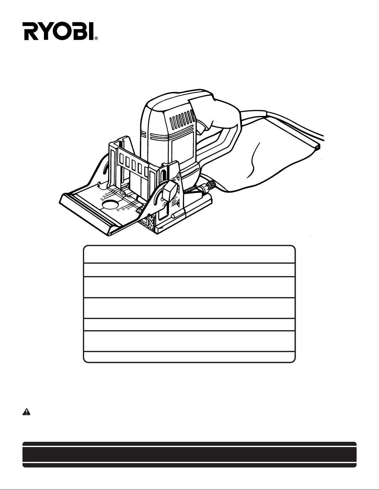
PLATE JOINER / JM80
DOUBLE INSULATED
SPECIFICATIONS:
No Load Speed 10,000 rpm
Rating 120 volts, 60 Hz, AC
6.0 Amperes
Fence Angle Adjustment
With 45° Positive Stops 0 - 135°
Fence Height Adjustment 0 - 2 In.
Depth Of Cut
With Micro Depth Of Cut Adjustment 0 - 5/8 In. (16mm)
Net Weight 6.8 lbs
THANK YOU FOR BUYING A RYOBI PLATE JOINER.
Your new plate joiner has been engineered and manufactured to Ryobi's high standard for dependability, ease of operation,
and operator safety. Properly cared for, it will give you years of rugged, trouble-free performance.
CAUTION: Carefully read through this entire owner's manual before using your new plate joiner. Pay close
attention to the Rules for Safe Operation, Warnings, and Cautions. If you use your plate joiner properly and only for what it
is intended, you will enjoy years of safe, reliable service.
Thank you again for buying a Ryobi plate joiner.
SAVE THIS MANUAL FOR FUTURE REFERENCE

Table of Contents
1. Table of Contents / Introduction ...............................................................2
2. Rules For Safe Operation ..................................................................... 4-6
3. Features ................................................................................................ 7-8
4. Adjustments .........................................................................................9-10
5. Operation........................................................................................... 11-16
6. Maintenance ......................................................................................17-19
7. Accessories ............................................................................................. 19
8. Troubleshooting...................................................................................... 20
9. Service Information ................................................................................22
INTRODUCTION
Spline joinery is one of the strongest methods of joinery
used in woodworking. When glue is properly applied to a
spline and to the joint area of the wood pieces being
connected, a large surface area receives the adhesion
properties of the glue. This forms a very strong joint.
Traditional spline joinery requires cutting slots with a router
or table saw. Small, thin strips of wood must then be cut to
fit inside the slots and act as splines.
Newer methods of spline joinery use a plate or biscuit
joiner to cut precise mating oval slots in adjoining boards.
Your new plate joiner is a fast, simple, and accurate plunge
cutting tool that can be used for this purpose. It can be
used to cut slots in hardwood, softwood, plywood, particle
board, and other pressed woods.
Football shaped wafers, called biscuits, are then placed
inside the slots with glue and used to help line up adjoining
surfaces. When a water based glue is used, the biscuits
swell in the joint, making an extremely strong and firm
bond. White glue, yellow glue, carpenters glue, hide glue,
and aliphatic resin glue are examples of water based glues.
This bonding technique has traditionally been limited to
making edge-to-edge joints. However, with the use of your
new plate joiner, biscuits can now be easily used to connect butt, miter, and T-joints. Biscuit joining can be as
strong as mortise and tenon, tongue and groove, standard
spline, and doweled joints. In most cases the material
around the biscuit will break before the biscuit itself will
break. A greater surface area is exposed to glue in a biscuit
joint, making the seams stronger.
Page 2
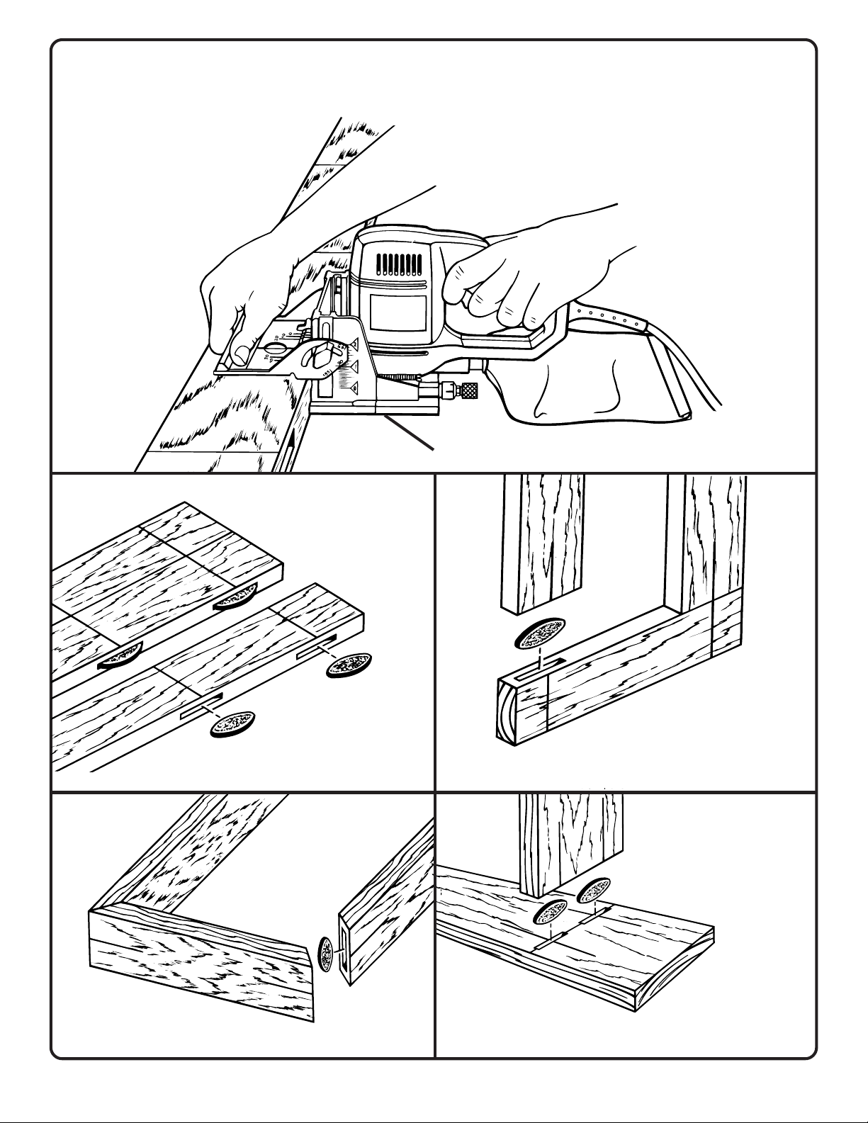
TYPICAL APPLICATIONS
PLATE JOINER / JM80
EDGE-TO-EDGE JOINTS
MITER JOINTS T- JOINT
Page 3
BUTT JOINTS
RULES FOR SAFE OPERATION
SAFETY GLASSES
FORESIGHT IS BETTER
THAN NO SIGHT
R
WEAR YOUR
THE PURPOSE OF SAFETY SYMBOLS IS TO ATTRACT YOUR ATTENTION TO POSSIBLE DANGERS. THE
SAFETY SYMBOLS, AND THE EXPLANATIONS WITH THEM, DESERVE YOUR CAREFUL ATTENTION AND
UNDERSTANDING. THE SAFETY WARNINGS DO NOT BY THEMSELVES ELIMINATE ANY DANGER. THE
INSTRUCTIONS OR WARNINGS THEY GIVE ARE NOT SUBSTITUTES FOR PROPER ACCIDENT PREVENTION
MEASURES.
SYMBOL MEANING
SAFETY ALERT SYMBOL:
Indicates caution or warning. May be used in conjunction with other symbols or pictographs.
WARNING: Failure to obey a safety warning can result in serious injury to yourself or to
others. Always follow the safety precautions to reduce the risk of fire, electric shock and
personal injury.
CAUTION: Failure to obey a safety warning may result in property damage or personal injury
to yourself or to others. Always follow the safety precautions to reduce the risk of fire, electric
shock and personal injury.
DOUBLE INSULATION
Your Ryobi power tool is double insulated. This means you
are separated from the tool's electrical system by two complete
sets of electrical insulation. This extra layer of insulation is
intended to protect the user from electrical shock due to a
break in the wiring insulation. All exposed metal parts are
isolated from the internal metal motor components with
protecting insulation. Double insulated tools do not need to
be grounded.
WARNING:
The double insulated system is intended to protect the
user from shock resulting from a break in the tool's
internal wiring. Observe all normal safety precautions
related to avoiding electrical shock.
WARNING:
The operation of any plate joiner can result in foreign objects being thrown into your
SAFETY GLASSES
FORESIGHT IS BETTE
THAN NO SIGHT
eyes, which can result in severe eye damage. Before beginning power tool operation,
always wear safety goggles or safety glasses with side shields and a full face shield
when needed. We recommend Wide Vision Safety Mask for use over eyeglasses or
standard safety glasses with side shields.
IMPORTANT
Servicing of a tool with double insulation requires extreme
care and knowledge of the system and should be performed
only by a qualified service technician. For service we
suggest you return the tool to your nearest Ryobi
AUTHORIZED SERVICE ORGANIZATION for repair.
When servicing use only identical Ryobi replacement
parts.
WARNING:
Do not attempt to operate this tool until you have read
thoroughly and understand completely all instructions,
safety rules, etc. contained in this manual. Failure to
comply can result in accidents involving fire, electric
shock, or serious personal injury. Save owner's manual
and review frequently for continuing safe operation, and
instructing others who may use this tool.
Look for this symbol to point out important safety precautions.
It means attention!!! Your safety is involved.
Page 4

READ ALL INSTRUCTIONS
1. KNOW YOUR POWER TOOL - Read owner's
manual carefully. Learn its applications and
limitations as well as the specific potential
hazards related to this tool.
2. GUARD AGAINST ELECTRICAL SHOCK
BY PREVENTING BODY CONTACT WITH
GROUNDED SURFACES. For example:
Pipes, radiators, ranges, refrigerator
enclosures.
3. KEEP WORK AREA CLEAN. Cluttered areas
and benches invite accidents.
4. AVOID DANGEROUS ENVIRONMENT.
Don't use power tools in damp or wet locations
or expose to rain. Keep work area well lit.
5. KEEP CHILDREN AND VISITORS AWAY.
All visitors should wear safety glasses and be
kept a safe distance from work area. Do not let
visitors contact tool or extension cord.
6. STORE IDLE TOOLS. When not in use tools
should be stored in a dry, high or locked-up
place – out of the reach of children.
7. DON'T FORCE TOOL. It will do the job better
and safer at the rate for which it was designed.
8. USE RIGHT TOOL. Don't force small tool or
attachment to do the job of a heavy duty tool.
Don't use tool for purpose not intended – for
example – Don't use a circular saw for cutting
tree limbs or logs.
9. DRESS PROPERLY. Do not wear loose
clothing or jewelry. They can be caught in
moving parts. Rubber gloves and non-skid
footwear are recommended when working
outdoors. Also, wear protective hair covering
to contain long hair and keep it from being
drawn into air vents.
10. ALWAYS WEAR SAFETY GLASSES WITH
SIDE SHIELDS. Everyday eyeglasses have
only impact resistant lenses; they are NOT
safety glasses.
11. PROTECT YOUR LUNGS. Wear a face or
dust mask if operation is dusty.
12. PROTECT YOUR HEARING. Wear hearing
protection during extended periods of
operation.
13. DON'T ABUSE CORD. Never carry tool by
cord or yank it to disconnect from receptacle.
Keep cord from heat, oil, and sharp edges.
14. SECURE WORK. Use clamps or a vise to
hold work. It's safer than using your hand and
it frees both hands to operate tool.
15. DON'T OVERREACH. Keep proper footing
and balance at all times. Do not use on a
ladder or unstable support.
16. MAINTAIN TOOLS WITH CARE. Keep tools
sharp at all times, and clean for best and
safest performance. Follow instructions for
lubricating and changing accessories.
17. DISCONNECT TOOLS. When not in use,
before servicing, or when changing
attachments, blades, bits, cutters, etc., all
tools should be disconnected.
18. REMOVE ADJUSTING KEYS AND
WRENCHES. Form habit of checking to see
that keys and adjusting wrenches are removed
from tool before turning it on.
19. AVOID ACCIDENTAL STARTING. Don't
carry plugged-in tool with finger on switch. Be
sure switch is off when plugging in.
20. MAKE SURE YOUR EXTENSION CORD IS
IN GOOD CONDITION. When using an
extension cord, be sure to use one heavy
enough to carry the current your product will
draw. An undersized cord will cause a drop in
line voltage resulting in loss of power and
overheating. A wire gage size (A.W.G.) of at
least 12 is recommended for an extension
cord 100 feet or less in length. A cord exceeding
100 feet is not recommended. If in doubt, use
the next heavier gage. The smaller the gage
number, the heavier the cord.
21. OUTDOOR USE EXTENSION CORDS.
When tool is used outdoors, use only extension
cords intended for use outdoors. Outdoor
approved cords are marked with the suffix WA, for example - SJTW-A or SJOW-A.
22. KEEP BLADES CLEAN AND SHARP. Sharp
blades minimize stalling and kickback.
23. KEEP HANDS AWAY FROM CUTTING
AREA. Keep hands away from blades. Do not
reach underneath work while blade is rotating.
WARNING: BLADES COAST AFTER TURN
OFF.
Page 5

RULES FOR SAFE OPERATION (Continued)
24. NEVER USE IN AN EXPLOSIVE
ATMOSPHERE. Normal sparking of the motor
could ignite flammable liquids, gases, or
fumes.
25. INSPECT TOOL CORDS PERIODICALLY
and if damaged, have repaired by an
authorized service facility. Stay constantly
aware of cord location and keep it well away
from the rotating blade.
26. INSPECT EXTENSION CORDS
PERIODICALLY and replace if damaged.
27. KEEP HANDLES DRY, CLEAN, AND FREE
FROM OIL AND GREASE. Always use a
clean cloth when cleaning. Never use brake
fluids, gasoline, petroleum-based products,
or any strong solvents to clean your tool.
28. STAY ALERT AND EXERCISE CONTROL.
Watch what you are doing and use common
sense. Do not operate tool when you are tired.
Do not rush.
29. CHECK DAMAGED PARTS. Before further
use of the tool, a guard or other part that is
damaged should be carefully checked to
determine that it will operate properly and
perform its intended function. Check for
alignment of moving parts, binding of moving
parts, breakage of parts, mounting, and any
other conditions that may affect its operation.
A guard or other part that is damaged should
be properly repaired or replaced by an
authorized service center.
30. DO NOT USE TOOL IF SWITCH DOES NOT
TURN IT ON AND OFF. Have switches
replaced by an authorized service center.
31. DO NOT OPERATE THIS TOOL WHILE
UNDER THE INFLUENCE OF DRUGS,
ALCOHOL, OR ANY MEDICATION.
32. GUARD AGAINST KICKBACK. Kickback
occurs when the blade stalls rapidly and the
plate joiner is driven in the direction opposite
blade rotation. Release switch immediately if
blade binds or joiner stalls.
33. USE ONLY 4 INCH DIAMETER SPECIFIED
BLADES. Do not use blades with incorrect
size holes. Never use blade washers or bolts
that are defective, incorrect, or not specified.
34. AVOID CUTTING NAILS. Inspect for and
remove all nails from lumber before cutting.
35. NEVER touch the blade or other moving parts
during use.
36. NEVER start a tool when the blade is in
contact with the workpiece.
37. NEVER lay a tool down before the blade has
come to a complete stop.
38. POLARIZED PLUGS. To reduce the risk of
electric shock, this equipment has a polarized
plug (one blade is wider than the other). This
plug will fit in a polarized outlet only one way.
If the plug does not fit fully in the outlet,
reverse the plug. If it still does not fit, contact
a qualified electrician to install the proper
outlet. Do not change the plug in any way.
39. WHEN SERVICING USE ONLY IDENTICAL
RYOBI REPLACEMENT PARTS.
40. SAVE THESE INSTRUCTIONS. Refer to them
frequently and use them to instruct others
who may use this tool. If you loan someone
this tool, loan them these instructions also.
WARNING:
Some dust created by power sanding, sawing,
grinding, drilling, and other construction activities
contains chemicals known to cause cancer, birth
defects or other reproductive harm. Some examples
of these chemicals are:
• lead from lead-based paints,
• crystalline silica from bricks and cement and
other masonry products, and
• arsenic and chromium from chemically-treated
lumber.
Your risk from these exposures varies, depending
on how often you do this type of work. To reduce
your exposure to these chemicals: work in a well
ventilated area, and work with approved safety
equipment, such as those dust masks that are
specially designed to filter out microscopic particles.
SAVE THESE INSTRUCTIONS
Page 6
FEATURES
Your Plate Joiner has been designed for making fast, accurate,
and simple plunge cuts in wood, etc. so that biscuits can be
used to join two or more boards together. When used
properly and only for what it is intended, this versatile tool will
give you years of trouble-free performance. It is professionally
engineered, but its ease of operation allows the amateur to
produce work that is beautiful and precise.
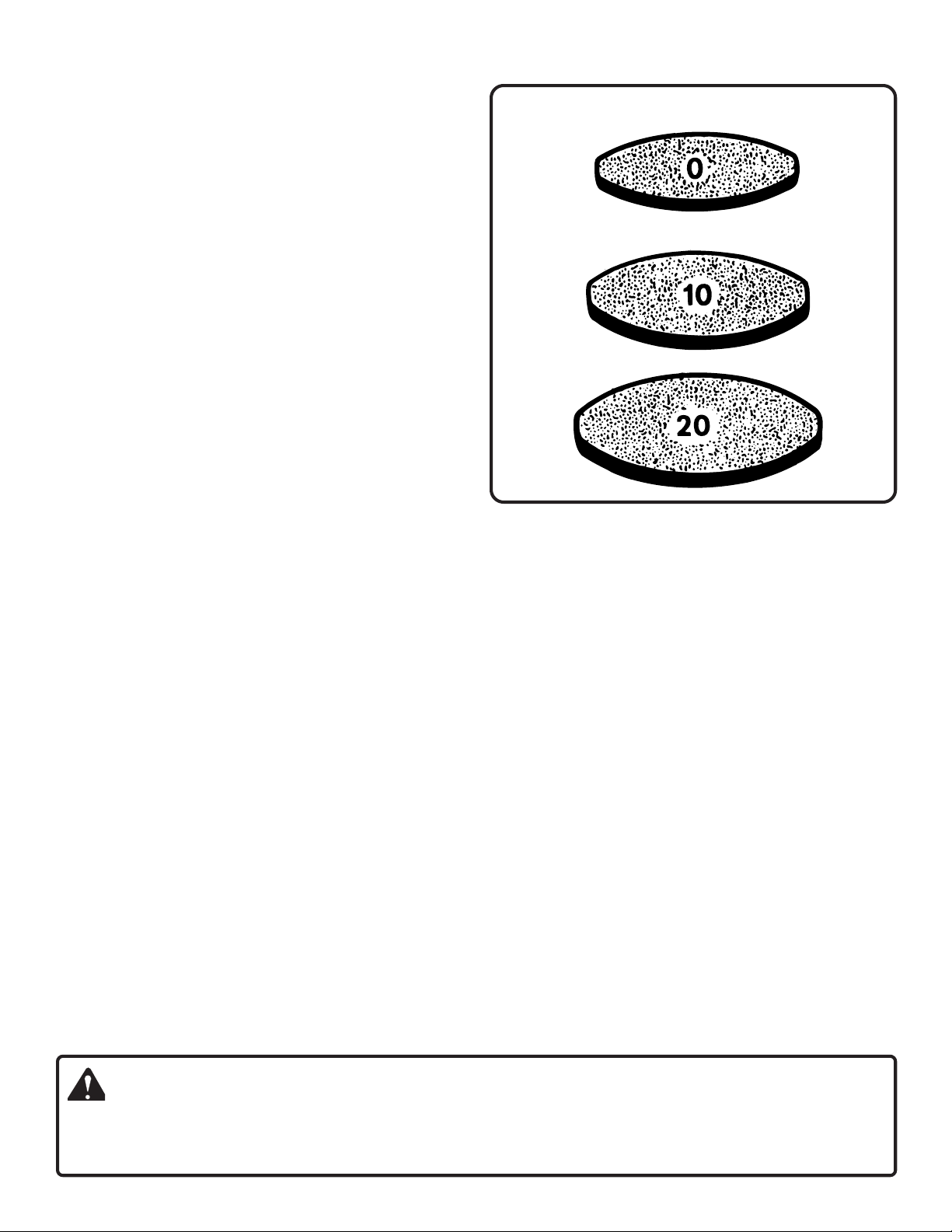
#0 = 5/8 IN. X 1-13/16 IN.
SWITCH
To turn your plate joiner ON, depress the switch trigger.
Release switch trigger to turn your plate joiner OFF.
MOTOR
Your plate joiner has a powerful motor with sufficient power
to handle tough cutting jobs. It develops a no load speed of
10,000 RPM.
CARBIDE TIPPED BLADE
Your plate joiner has an 8 tooth carbide tipped blade for
cutting biscuit slots.
BISCUITS
See Figure 1.
Biscuits are available in three standard sizes:
#0 (5/8 in. x 1-13/16 in.)
#10 (13/16 in. x 2-1/16 in.)
#20 (15/16 in. x 2-5/16 in.)
NOTE: Biscuits swell rapidly upon contact with water-based
woodworking glues.
ADJUSTABLE FENCE / FRONT HANDLE
Your plate joiner has an adjustable fence. By loosening the
height adjustment knobs, the angle of the fence can be set
at angles from 0° to 135°, with positive stop settings in
increments of 45°. The height of the fence can be set
between 0 in. - 2 in. with a scale showing 0 in. - 1-1/2 in.
The front handle is part of the adjustable fence and should
always be used to guide and balance your plate joiner,
providing ease of operation and maintaining safe control.
NON-SKID BACKING PAD
The fence on your plate joiner is padded with a non-skid
backing pad to hold it stationary against the workpiece. It
helps prevent skidding when making cuts. It also prevents
marring of the workpiece from your plate joiner when making
cuts.
APPLICATIONS
(Use only for the purpose listed below)
1. Cutting precise mating oval slots in hard wood, soft wood,
plywood, particle board, etc. for spline joinery applications.
#10 = 13/16 IN. X 2-1/16 IN.
#20 = 15/16 IN X 2-5/16 IN.
Fig. 1
ELECTRICAL CONNECTION
Your plate joiner has a precision built electric motor. It should
be connected to a power supply that is 120 volts, 60 Hz,
AC only (normal household current). Do not operate this
tool on direct current (DC). A voltage drop of more than 10
percent will cause a loss of power and overheating. If your
plate joiner does not operate when plugged into an outlet,
double-check the power supply.
DEPTH ADJUSTMENT KNOB
A spring loaded depth adjustment knob makes it possible to
make proper settings for three standard size biscuits. Fine
adjustments to the cutting depth can be made with a knurled
adjustment knob and jam nut located behind the depth
adjustment knob. Once the correct depth setting has been
made for one biscuit size, the other two depth settings will be
automatically set.
DUSTLESS FEATURE
The dust bag provides a dust collection system. Wood
particles are drawn up through a tunnel in the base and
collect in the dust bag during cutting operations.
INDICATOR MARKS
Centerline and line of cut indicator marks have been provided
on your plate joiner.
See Figure 2.
WARNING:
Your plate joiner should never be connected to power supply when you are assembling parts, making adjustments,
assembling or removing blades, cleaning or when not in use. Disconnecting your plate joiner will prevent accidental
starting that could cause serious personal injury.
Page 7
 Loading...