


 Loading...
Model Da-P1
Machine Code:
M187
Field Service Manual
January, 2015

Important Safety Notices
Important Safety Notices
Prevention of Physical Injury
1.Before disassembling or assembling parts of the main machine and peripherals, make sure that the power cord of the main machine is unplugged.
2.The wall outlet should be near the machine and easily accessible.
3.Note that some components of the machine and the paper tray unit are supplied with electrical voltage even if the main power switch is turned off.
4.If any adjustment or operation check has to be made with exterior covers off or open while the main switch is turned on, keep hands away from electrified or mechanically driven components.
5.The inside and the metal parts of the fusing unit become extremely hot while the machine is operating. Be careful to avoid touching those components with your bare hands.
•To prevent a fire or explosion, keep the machine away from flammable liquids, gases, and aerosols.
Health Safety Conditions
1.Toner and developer is non-toxic, but if you get either of them in your eyes by accident, it may cause temporary eye discomfort. Immediately wash eyes with plenty of water. If unsuccessful, get medical attention.
2.This machine, which uses a high voltage power source, can generate ozone gas. High ozone density is harmful to human health. Therefore, the machine must be installed in a well-ventilated room.
Observance of Electrical Safety Standards
1.This machine and its peripherals must be serviced by a customer service representative who has completed the training course on those models.
2.The NVRAM on the system control board has a lithium battery which can explode if replaced incorrectly. Replace the NVRAM only with an identical one. The manufacturer recommends replacing the entire NVRAM. Do not recharge or burn this battery. Used NVRAM must be handled in accordance with local regulations.
1

Handling Toner
•Work carefully when removing paper jams or replacing toner bottles or cartridges to avoid spilling toner on clothing or the hands.
•If toner is inhaled, immediately gargle with large amounts of cold water and move to a well ventilated location. If there are signs of irritation or other problems, seek medical attention.
•If toner gets on the skin, wash immediately with soap and cold running water.
•If toner gets into the eyes, flush the eyes with cold running water or eye wash. If there are signs of irritation or other problems, seek medical attention.
•If toner is swallowed, drink a large amount of cold water to dilute the ingested toner. If there are signs of any problem, seek medical attention.
•If toner spills on clothing, wash the affected area immediately with soap and cold water. Never use hot water! Hot water can cause toner to set and permanently stain fabric.
•Always store toner and developer supplies such as toner and developer packages, cartridges, and bottles (including used toner and empty bottles and cartridges) out of the reach of children.
•Always store fresh toner supplies or empty bottles or cartridges in a cool, dry location that is not exposed to direct sunlight.
•Do not use a vacuum cleaner to remove spilled toner (including used toner). Vacuumed toner may cause a fire or explosion due to sparks or electrical contact inside the cleaner. However, it is possible to use a cleaner designed to be dust explosion-proof. If toner is spilled over the floor, sweep up spilled toner slowly and clean up any remaining toner with a wet cloth.
Safety and Ecological Notes for Disposal
1.Do not incinerate toner bottles or used toner. Toner dust may ignite suddenly when exposed to an open flame.
2.Dispose of used toner, the maintenance unit which includes developer or the organic photoconductor in accordance with local regulations. (These are non-toxic supplies.)
3.Dispose of replaced parts in accordance with local regulations.
4.When keeping used lithium batteries in order to dispose of them later, do not put more than 100 batteries per sealed box. Storing larger numbers or not sealing them apart may lead to chemical reactions and heat build-up.
2
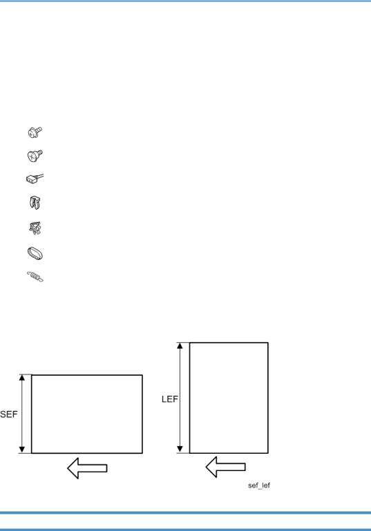
Symbols, Abbreviations and Trademarks
This manual uses several symbols and abbreviations. The meaning of those symbols and abbreviations are as follows:
Symbol |
What is means |
|
|
|
Screw |
|
|
|
Shoulder screw |
|
|
|
Connector |
|
|
|
Clip ring |
|
|
|
Clamp |
|
|
|
Timing belt |
|
|
|
Spring |
|
|
SEF |
Short Edge Feed |
|
|
LEF |
Long Edge Feed |
|
|
Trademarks
Adobe, Acrobat, PostScript, PostScript 3, and Reader are either registered trademarks or trademarks of Adobe Systems Incorporated in the United States and/or other countries.
3

Mac OS, OS X, and Safari are trademarks of Apple Inc., registered in the United States and other countries.
Firefox® is a registered trademark of the Mozilla Foundation. Java is a registered trademark of Oracle and/or its affiliates.
JAWS® is a registered trademark of Freedom Scientific, Inc., St. Petersburg, Florida and/or other countries.
Microsoft®, Windows®, Windows Server®, Windows Vista®, and Internet Explorer® are either registered trademarks or trademarks of Microsoft Corporation in the United States and/or other countries.
Monotype is a registered trademark of Monotype Imaging Inc.
NetWare, IPX, IPX/SPX, NCP, and NDS are either registered trademarks or trademarks of Novell, Inc. PCL® is a registered trademark of Hewlett-Packard Company.
The proper name of Internet Explorer 6 is Microsoft® Internet Explorer® 6. The proper name of Internet Explorer 8 is Windows® Internet Explorer® 8. The proper names of the Windows operating systems are as follows:
•The product names of Windows XP are as follows: Microsoft® Windows® XP Professional Edition Microsoft® Windows® XP Home Edition Microsoft® Windows® XP Media Center Edition Microsoft® Windows® XP Tablet PC Edition
•The product names of Windows Vista are as follows: Microsoft® Windows Vista® Ultimate
Microsoft® Windows Vista® Business Microsoft® Windows Vista® Home Premium Microsoft® Windows Vista® Home Basic Microsoft® Windows Vista® Enterprise
•The product names of Windows 7 are as follows: Microsoft® Windows® 7 Home Premium Microsoft® Windows® 7 Professional Microsoft® Windows® 7 Ultimate
Microsoft® Windows® 7 Enterprise
•The product names of Windows 8 are as follows: Microsoft® Windows® 8
Microsoft® Windows® 8 Pro
4

Microsoft® Windows® 8 Enterprise
•The product names of Windows 8.1 are as follows: Microsoft® Windows® 8.1
Microsoft® Windows® 8.1 Pro Microsoft® Windows® 8.1 Enterprise
•The product names of Windows Server 2003 are as follows: Microsoft® Windows Server® 2003 Standard Edition Microsoft® Windows Server® 2003 Enterprise Edition
•The product names of Windows Server 2003 R2 are as follows: Microsoft® Windows Server® 2003 R2 Standard Edition Microsoft® Windows Server® 2003 R2 Enterprise Edition
•The product names of Windows Server 2008 are as follows: Microsoft® Windows Server® 2008 Standard
Microsoft® Windows Server® 2008 Enterprise
•The product names of Windows Server 2008 R2 are as follows: Microsoft® Windows Server® 2008 R2 Standard
Microsoft® Windows Server® 2008 R2 Enterprise
•The product names of Windows Server 2012 are as follows: Microsoft® Windows Server® 2012 Foundation Microsoft® Windows Server® 2012 Essentials
Microsoft® Windows Server® 2012 Standard
•The product names of Windows Server 2012 R2 are as follows: Microsoft® Windows Server® 2012 R2 Foundation Microsoft® Windows Server® 2012 R2 Essentials
Microsoft® Windows Server® 2012 R2 Standard
Other product names used herein are for identification purposes only and might be trademarks of their respective companies. We disclaim any and all rights to those marks.
Microsoft product screen shots reprinted with permission from Microsoft Corporation.
5

TABLE OF CONTENTS |
|
Important Safety Notices................................................................................................................................... |
1 |
Important Safety Notices............................................................................................................................... |
1 |
Prevention of Physical Injury................................................................................................................. |
1 |
Health Safety Conditions...................................................................................................................... |
1 |
Observance of Electrical Safety Standards......................................................................................... |
1 |
Handling Toner...................................................................................................................................... |
2 |
Safety and Ecological Notes for Disposal................................................................................................... |
2 |
Symbols, Abbreviations and Trademarks......................................................................................................... |
3 |
Trademarks..................................................................................................................................................... |
3 |
1. Product Information |
|
Product Overview............................................................................................................................................. |
15 |
Component Layout....................................................................................................................................... |
15 |
Paper Path.................................................................................................................................................... |
16 |
Drive Layout.................................................................................................................................................. |
17 |
Machine Codes and Peripheral Configuration............................................................................................. |
18 |
Machine Codes and Peripheral Configuration......................................................................................... |
18 |
Specifications.................................................................................................................................................... |
21 |
2. Installation |
|
Installation Requirements................................................................................................................................. |
23 |
Environment.................................................................................................................................................. |
23 |
Machine Space Requirements.................................................................................................................... |
24 |
Machine Dimensions................................................................................................................................... |
24 |
Power Requirements.................................................................................................................................... |
25 |
Main Machine Installation............................................................................................................................... |
26 |
Accessory Check.......................................................................................................................................... |
26 |
Instructions for the Customers...................................................................................................................... |
26 |
Moving the Machine................................................................................................................................... |
26 |
Security Settings........................................................................................................................................... |
28 |
Changing an Administrator's Password............................................................................................. |
28 |
Configuring SSL/TLS........................................................................................................................... |
28 |
Paper Feed Unit TK2010................................................................................................................................ |
29 |
Component Check....................................................................................................................................... |
29 |
Installation Procedure.................................................................................................................................. |
29 |
6

USB Device Server Option Type M12........................................................................................................... |
31 |
Component Check....................................................................................................................................... |
31 |
Interface Board Surface...................................................................................................................... |
31 |
Installation Procedure.................................................................................................................................. |
32 |
What Do the LED Indications Mean?................................................................................................ |
35 |
Notes for Energy Save Mode Setting................................................................................................ |
36 |
IP Address Setting........................................................................................................................................ |
36 |
SD Card Appli Move....................................................................................................................................... |
39 |
Overview...................................................................................................................................................... |
39 |
Notes on Using the SD Merge Function.................................................................................................... |
39 |
SD Card Applications.................................................................................................................................. |
40 |
Move Exec................................................................................................................................................... |
40 |
Undo Exec.................................................................................................................................................... |
42 |
Settings for @Remote Service.......................................................................................................................... |
44 |
Check points before making @Remote settings......................................................................................... |
44 |
Execute the @Remote Settings.................................................................................................................... |
44 |
3. Preventive Maintenance |
|
Preventive Maintenance Tables...................................................................................................................... |
49 |
Preventive Maintenance Tables.................................................................................................................. |
49 |
Image Quality Standards................................................................................................................................ |
50 |
Image Quality Standards............................................................................................................................ |
50 |
Paper Transfer Quality Standards.................................................................................................................. |
51 |
Paper Transfer Quality Standards.............................................................................................................. |
51 |
4. Replacement and Adjustment |
|
General Cautions............................................................................................................................................. |
53 |
Notes on the Main Power Switch............................................................................................................... |
53 |
Characteristics of the Push Switch (DC Switch)................................................................................. |
53 |
Shutdown Method............................................................................................................................... |
54 |
Forced Shutdown................................................................................................................................ |
55 |
Special Tools ................................................................................................................................................... |
56 |
Exterior Covers................................................................................................................................................. |
57 |
Front Cover................................................................................................................................................... |
57 |
Left Cover...................................................................................................................................................... |
58 |
7

Right Cover................................................................................................................................................... |
60 |
Rear Cover, Rear Lower Cover................................................................................................................... |
63 |
By-pass Tray................................................................................................................................................. |
66 |
Upper Cover................................................................................................................................................ |
67 |
Operation Panel........................................................................................................................................... |
68 |
LED Optics........................................................................................................................................................ |
72 |
LED Unit........................................................................................................................................................ |
72 |
PCDU................................................................................................................................................................. |
78 |
PCDU............................................................................................................................................................ |
78 |
Toner Cartridge................................................................................................................................................ |
79 |
Toner Cartridge............................................................................................................................................ |
79 |
Image Transfer.................................................................................................................................................. |
81 |
Image Transfer Roller................................................................................................................................... |
81 |
Drive Unit.......................................................................................................................................................... |
83 |
Main Motor.................................................................................................................................................. |
83 |
Exit/Reverse Motor..................................................................................................................................... |
84 |
Registration Clutch....................................................................................................................................... |
86 |
Paper Feed Clutch........................................................................................................................................ |
86 |
By-pass Feed Clutch.................................................................................................................................... |
87 |
By-pass Bottom Plate Clutch........................................................................................................................ |
89 |
Drive Unit...................................................................................................................................................... |
89 |
Gear Unit...................................................................................................................................................... |
89 |
Toner Supply Clutch.................................................................................................................................... |
92 |
Relay Clutch................................................................................................................................................. |
93 |
Duplex Clutch............................................................................................................................................... |
94 |
Junction Gate Solenoid............................................................................................................................... |
95 |
Fusing................................................................................................................................................................ |
96 |
Fusing Unit.................................................................................................................................................... |
96 |
Upper Fusing Unit, Lower Fusing Unit........................................................................................................ |
98 |
Fusing Pressure Roller.................................................................................................................................. |
99 |
Fusing Lamp, Hot Roller............................................................................................................................ |
100 |
Thermostat.................................................................................................................................................. |
104 |
Thermistor................................................................................................................................................... |
104 |
8
Hot Roller Stripper..................................................................................................................................... |
106 |
Paper Feed..................................................................................................................................................... |
107 |
Paper Feed Tray........................................................................................................................................ |
107 |
Paper Feed Roller...................................................................................................................................... |
107 |
Friction Roller, Torque Limiter................................................................................................................... |
108 |
Paper End Sensor...................................................................................................................................... |
109 |
By-pass Feed Unit...................................................................................................................................... |
110 |
By-pass Feed Roller................................................................................................................................... |
112 |
By-pass Friction Pad.................................................................................................................................. |
114 |
By-pass Paper End Sensor........................................................................................................................ |
115 |
By-pass Bottom Plate HP Sensor.............................................................................................................. |
116 |
Paper Size Detection Switch..................................................................................................................... |
117 |
Paper Transport.............................................................................................................................................. |
119 |
Paper Exit Unit........................................................................................................................................... |
119 |
Paper Exit Sensor....................................................................................................................................... |
121 |
Paper Overflow Sensor............................................................................................................................. |
121 |
Duplex Reverse Sensor............................................................................................................................. |
121 |
Duplex Entrance Sensor............................................................................................................................ |
123 |
Registration Roller (Driven)....................................................................................................................... |
123 |
Registration Roller (Drive)......................................................................................................................... |
126 |
Registration Sensor.................................................................................................................................... |
128 |
Electrical Components................................................................................................................................... |
130 |
Controller Box............................................................................................................................................ |
130 |
PSU............................................................................................................................................................. |
131 |
Controller Board........................................................................................................................................ |
134 |
Before replacing the controller board in the model without HDD................................................ |
134 |
Replacement Procedure................................................................................................................... |
134 |
After installing the controller board................................................................................................. |
136 |
NVRAM on the Controller Board............................................................................................................. |
136 |
BCU............................................................................................................................................................ |
137 |
EEPROM on the BCU................................................................................................................................ |
138 |
Toner End Sensor...................................................................................................................................... |
139 |
HVPS........................................................................................................................................................... |
140 |
9

HVPS with Bracket..................................................................................................................................... |
140 |
PCDU Cooling Fan.................................................................................................................................... |
141 |
PCDU Cooling Fan with Duct................................................................................................................... |
141 |
PSU Cooling Fan....................................................................................................................................... |
142 |
DC Switch.................................................................................................................................................. |
142 |
Front Cover Interlock Switch..................................................................................................................... |
143 |
Front Cover Interlock Switch with Bracket............................................................................................... |
144 |
Rear Cover Interlock Switch..................................................................................................................... |
144 |
DIMM......................................................................................................................................................... |
145 |
Temp Humid Sensor.................................................................................................................................. |
147 |
Envelope Lever Detection Switch............................................................................................................. |
147 |
5. System Maintenance |
|
Service Program Mode................................................................................................................................. |
149 |
SP Tables.................................................................................................................................................... |
149 |
Enabling and Disabling Service Program Mode.................................................................................... |
149 |
Entering SP Mode............................................................................................................................. |
149 |
Exiting SP Mode............................................................................................................................... |
149 |
Types of SP Modes.................................................................................................................................... |
150 |
Service Mode Lock/Unlock..................................................................................................................... |
150 |
Updating the Firmware.................................................................................................................................. |
151 |
Overview.................................................................................................................................................... |
151 |
Type of Firmware....................................................................................................................................... |
151 |
Updating Firmware................................................................................................................................... |
152 |
Before You Begin.............................................................................................................................. |
152 |
Preparation........................................................................................................................................ |
153 |
Updating Procedure......................................................................................................................... |
153 |
Firmware Update Error..................................................................................................................... |
156 |
Recovery after Power Loss............................................................................................................... |
156 |
Handling Firmware Update Errors........................................................................................................... |
157 |
Uploading/Downloading NVRAM Data.................................................................................................... |
162 |
Uploading Content of NVRAM to an SD Card...................................................................................... |
162 |
Downloading an SD Card to NVRAM.................................................................................................... |
163 |
Capturing Log to SD card............................................................................................................................. |
164 |
10

Overview.................................................................................................................................................... |
164 |
Security of the Operation Log.......................................................................................................... |
165 |
Retrieving the Debug Logs........................................................................................................................ |
165 |
Procedure for Retrieving the Debug Log......................................................................................... |
166 |
Address Book Upload/Download.............................................................................................................. |
167 |
Information List........................................................................................................................................... |
167 |
Upload (Backup) to SD Card................................................................................................................... |
167 |
Download (Restore) to Machine.............................................................................................................. |
168 |
Erasing the Backup Data.......................................................................................................................... |
168 |
6. Troubleshooting |
|
Self-Diagnostic Mode................................................................................................................................... |
169 |
Self-Diagnostic Mode at Power On......................................................................................................... |
169 |
Service Call.................................................................................................................................................... |
170 |
Summary.................................................................................................................................................... |
170 |
When a Level “D” SC code occurs................................................................................................. |
170 |
SC100........................................................................................................................................................ |
171 |
SC200 (LED Optics)................................................................................................................................. |
171 |
SC300 (Image Processing – 1)............................................................................................................... |
173 |
SC400 (Image Processing – 2)............................................................................................................... |
175 |
SC500 (Paper Feed and Fusing)............................................................................................................. |
176 |
SC600 (Device Communication)............................................................................................................. |
185 |
SC700 (Peripherals)................................................................................................................................. |
196 |
SC800 (Controller)................................................................................................................................... |
197 |
SC900 (Others)......................................................................................................................................... |
262 |
Jam Detection................................................................................................................................................. |
269 |
Jam Displays.............................................................................................................................................. |
269 |
Jam History................................................................................................................................................. |
269 |
Sensor Position Layout.............................................................................................................................. |
270 |
Sensor Position........................................................................................................................................... |
270 |
Main Machine.................................................................................................................................. |
271 |
Optional Bank................................................................................................................................... |
272 |
Troubleshooting............................................................................................................................................. |
273 |
Test Pattern Printing.................................................................................................................................... |
273 |
11

Image Position Adjustment........................................................................................................................ |
274 |
Registration Adjustment............................................................................................................................. |
274 |
Print Area........................................................................................................................................... |
274 |
Adjustment Reference Values........................................................................................................... |
275 |
Adjustment Procedure....................................................................................................................... |
275 |
Image Problem.......................................................................................................................................... |
275 |
Problem at Regular Intervals............................................................................................................ |
275 |
When Vertical Banding is Generated............................................................................................. |
277 |
When Black Spots are Generated on Print Image......................................................................... |
277 |
When Toner Smears Appear on the Backside of the Printouts..................................................... |
278 |
Paper Feed (Skew).................................................................................................................................... |
279 |
Recycled or Thin Paper Is Severely Curled after Printing....................................................................... |
279 |
Electrical Component Defects....................................................................................................................... |
280 |
Electrical Components.............................................................................................................................. |
280 |
Fuses........................................................................................................................................................... |
281 |
BCU.................................................................................................................................................... |
281 |
PSU.................................................................................................................................................... |
283 |
7. Energy Save |
|
Energy Save................................................................................................................................................... |
285 |
Energy Saver Modes................................................................................................................................ |
285 |
Sleep Mode Setting.......................................................................................................................... |
285 |
Weekly Timer.................................................................................................................................... |
286 |
Eco Night Mode............................................................................................................................... |
286 |
Fusing Off Mode............................................................................................................................... |
289 |
Fusing Heater Off on Stndby........................................................................................................... |
290 |
Return to Stand-by Mode................................................................................................................. |
290 |
Recommendation.............................................................................................................................. |
290 |
Energy Save Effectiveness........................................................................................................................ |
291 |
Paper Save..................................................................................................................................................... |
293 |
Effectiveness of Duplex/Combine Function............................................................................................ |
293 |
1. Duplex:.......................................................................................................................................... |
293 |
2. Combine mode:............................................................................................................................ |
293 |
3. Duplex + Combine:...................................................................................................................... |
294 |
12

Recommendation.............................................................................................................................. |
294 |
13

14

1. Product Information
Product Overview
Component Layout
No. |
Description |
No. |
Description |
|
|
|
|
1 |
Paper Feed Unit |
4 |
LED Head |
|
|
|
|
2 |
By-pass Tray |
5 |
PCDU |
|
|
|
|
3 |
Toner Cartridge |
6 |
Fusing Unit |
|
|
|
|
15

1. Product Information
Paper Path
No. |
Description |
No. |
Description |
|
|
|
|
1 |
Main Machine Paper Feed Path |
3 |
Duplex Paper Feed Path |
|
|
|
|
2 |
By-pass Paper Feed Path |
4 |
Optional Tray Paper Feed Path |
|
|
|
|
16
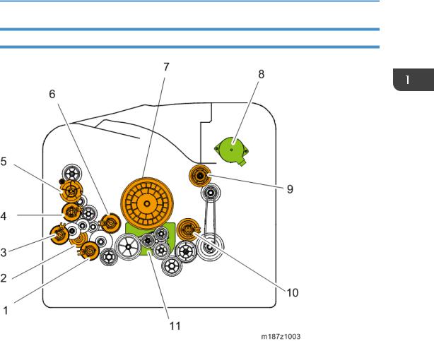
Product Overview
Drive Layout
No. |
Description |
No. |
Description |
|
|
|
|
1 |
Paper feed clutch |
7 |
Drum Gear |
|
|
|
|
2 |
Replay Clutch |
8 |
Exit/Reverse Motor |
|
|
|
|
3 |
By-pass Bottom Plate Clutch |
9 |
Fusing Drive Gear |
|
|
|
|
4 |
By-pass Feed Clutch |
10 |
Duplex Clutch |
|
|
|
|
5 |
Toner Supply Clutch |
11 |
Main Motor |
|
|
|
|
6 |
Registration Clutch |
|
|
|
|
|
|
17
1. Product Information
Machine Codes and Peripheral Configuration
Machine Codes and Peripheral Configuration
Main Frame
Item |
Machine Code |
Remarks |
|
|
|
|
|
|
M187-17 |
(NA) |
NEW |
|
|
|
|
SP 6430DN |
M187-27 |
(EU/AA) |
NEW |
|
|
|
|
|
M187-21 |
(CHN) |
NEW |
|
|
|
|
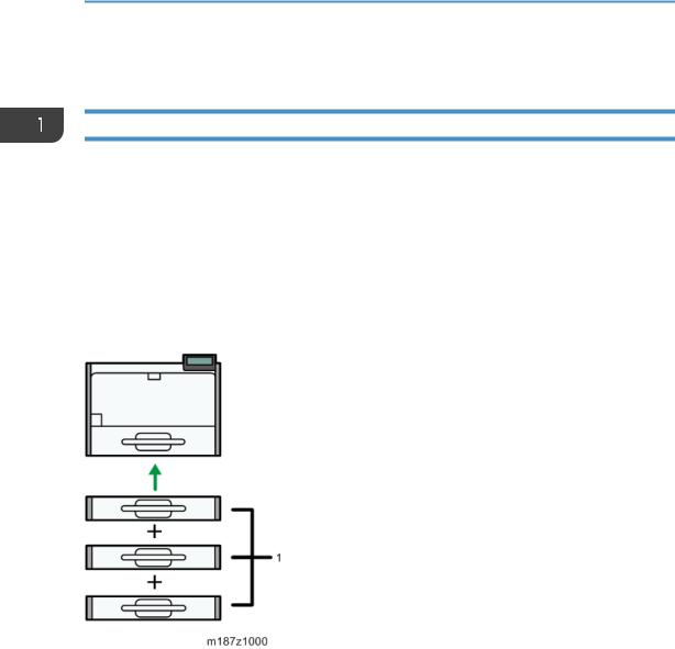
External Options
No. |
Item |
Machine Code |
Remarks |
|
|
|
|
|
|
1 |
Paper Feed Unit TK2010 |
M456-17 |
|
NEW |
|
|
|
|
|
Internal Options |
|
|
|
|
|
Item |
Machine Code |
Remarks |
|
|
|
|
|
|
IPDS Unit Type P4 |
M444-50 |
(NA) |
|
|
|
|
|
|
|
|
|
M444-51 |
(EU) |
|
|
|
|
|
|
|
|
M444-52 |
(AA/CHN) |
|
|
|
|
|
|
18
Machine Codes and Peripheral Configuration
Item |
Machine Code |
Remarks |
|
|
|
XPS Direct Print Option Type P4 |
M444-49 |
|
|
|
|
VM CARD Type W *1 |
M417-19 (NA) |
|
|
|
|
|
M417-20 (EU) |
|
|
|
|
|
M417-21 (AA/CHN) |
|
|
|
|
Memory Unit Type N |
M417-03 |
|
|
|
|
SD card for NetWare printing Type P4 |
M444-55 |
|
|
|
|
Hard Disk Drive Option Type P4 |
M444-42 |
|
|
|
|
IEEE802.11 Interface Unit Type O |
M417-06 (NA) |
|
|
|
|
USB Device Server Option Type M12 |
D3A7-28 (NA) |
|
|
|
|
|
D3A7-29 (EU/AA/CHN) |
|
|
|
|
IEEE1284 Interface Board Type A |
B679-17 |
|
|
|
|
*1: To install this, Memory Unit Type N and Hard Disk Drive Option Type P4 must first be installed.
Consumables for M187
Item |
Machine Code |
Remarks |
Yield |
|
|
|
|
|
|
Print Cartridge SP 6430A |
M915-17 (NA) |
|
|
|
|
|
|
|
|
Print Cartridge SP 6430E |
M915-27 (EU) |
|
10,000 pages |
|
|
|
|
(ISO) |
|
Print Cartridge SP 6430S |
M915-20 (AA) |
|
||
|
|
|
|
|
Print Cartridge SP 6430C |
M915-21 |
(CHN) |
NEW |
|
|
|
|
|
|
Drum Unit SP 6430 |
M919-17 |
|
25,000 pages |
|
|
|
|||
|
|
|
(3P/J) |
|
|
|
|
|
|
|
|
|
|
|
Maintenance Kit SP 6430 |
M920-17 |
(NA) |
|
90,000 pages |
|
|
|
|
(3P/J) |
|
M920-27 |
(EU) |
|
|
|
|
|
|
|
19

1. Product Information
•(ISO): The number of printable pages is based on pages that are compliant with ISO/IEC 19752 with the image density set as the factory default. ISO/IEC 19752 is an international standard for
measurement of printable pages, set by the International Organization for Standardization.
•(6%, 3P/J): A4/Letter 6% test chart, 3 pages/job.
•(3P/J): A4/Letter, 3 pages/job.
20

Specifications
Specifications
See "Appendices" for the following information:
•General Specifications
•Supported Paper Sizes
•Software Accessories
•Optional Equipment
21

1. Product Information
22
2. Installation
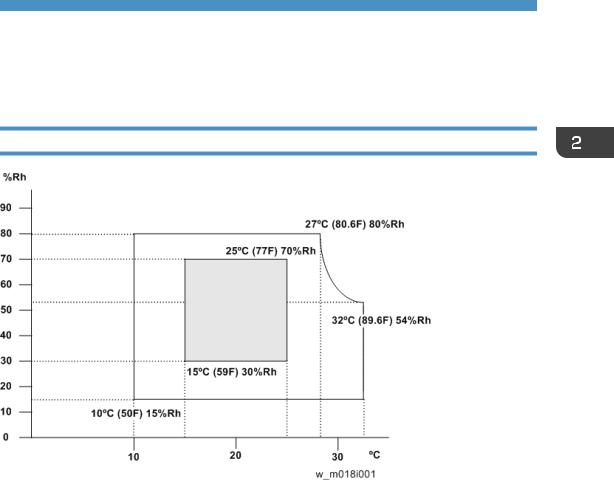
Installation Requirements
Environment
1.Temperature Range: 10°C to 32°C (50°F to 89.6°F)
2.Humidity Range: 15% to 80% RH
3.Ambient Illumination: Less than 1,500 lux (do not expose to direct sunlight)
4.Ventilation: More than 3 times/hr/person
5.Do not install the machine at locations over 2,000 m (6,562 ft.) above sea level.
23
2. Installation
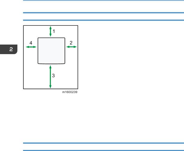
Machine Space Requirements
1 |
Rear |
Over 20 cm (7.9 inches) |
|
|
|
2 |
Right |
Over 10 cm (3.9 inches) |
|
|
|
3 |
Front |
Over 55 cm (21.7 inches) |
|
|
|
4 |
Left |
Over 10 cm (3.9 inches) |
|
|
|
Machine Dimensions
|
• |
Printer only: 459 mm (18.07 inches) |
|
Width |
• |
With an optional hard disk cover: 475 mm (18.70 inches) |
|
|
• |
With Intake louver: 464 mm (18.27 inches) |
|
|
|
||
|
• 392 mm (15.4 inches) |
||
Depth |
• |
With paper feed tray handle: 412 mm (16.22 inches) |
|
|
• |
With controller screw: 396.4 mm (15.61 inches) |
|
|
|
|
|
Height |
• |
Printer Only: 347.5 mm (13.68 inches) |
|
• |
With optional paper feed trays (TK2010×3): 719.5 mm (28.33 inches) |
||
|
|||
|
|
|
|
24

Installation Requirements
Power Requirements
•Make sure that the plug is firmly inserted in the outlet.
•Avoid multi-wiring.
•Be sure to ground the machine.
•Never place anything on the power cord.
1. |
Input voltage level: |
|
|
|
|
|
|
|
|
|
|
|
|
|
Destination |
Power supply voltage |
Frequency |
|
Rated current consumption |
|
|
|
|
|
|
|
|
|
NA |
120 V to 127 V |
60 Hz |
|
More than 10 A |
|
|
|
|
|
|
|
|
|
EU/AP/CHN |
220 V to 240V |
50 Hz/60 Hz |
|
5.3 A |
|
|
|
|
|
|
|
|
2. |
Permissible voltage fluctuation: |
|
|
|
||
|
|
|
|
|
|
|
|
Destination |
|
For printing images |
|
For operating |
|
|
|
|
|
|
|
|
|
NA |
|
+8.66 / -10% |
|
+8.66 / -15% |
|
|
|
|
|
|
|
|
|
EU/AP/CHN |
|
±10% |
|
±15% |
|
|
|
|
|
|
|
|
25

2. Installation
Main Machine Installation
• The M187 models are for installation by users.
Accessory Check
Description |
Q’ty |
|
|
Power cord |
1 |
|
|
Instructions for the Customers
Provide instructions on the following matters to customers. For detailed procedures, see the user manuals.
•Operating the printer function
•Installing consumables and loading paper
•Operating the main power switch
•Removing jammed paper
•Registering/changing/deleting data in the address book
•Providing precautions on use
•Connecting to computers (such as configuring the port setting)
•Giving a brief outline of the tabs in the drivers
Moving the Machine
•It is dangerous to handle the power cord plug with wet hands. Doing so could result in electric shock.
•Unplug the power cord from the wall outlet before you move the machine. While moving the machine, take care that the power cord is not damaged under the machine. Failing to take these precautions could result in fire or electric shock.
26
Main Machine Installation
•If you have to move the machine when the optional paper tray unit is attached, do not push on the main unit's top section. Doing so can cause the optional paper tray unit to detach, possibly resulting in injury.
•When disconnecting the power cord from the wall outlet, always pull the plug, not the cord. Pulling the cord can damage the power cord. Use of damaged power cords could result in fire or electric shock.
•The machine weighs approximately 22.5 kg (49.6 lb.). When moving the machine, use the inset grips on both sides, and lift slowly in pairs. The machine will break or cause injury if dropped.
•Do not hold the control panel while moving the machine. Doing so may damage the control panel, cause a malfunction, or result in injury.
•Be careful when moving the machine. Take the following precautions:
•Close all covers and trays, including the front cover and by-pass tray.
•If optional paper feed units are attached, remove them from the machine and move them separately.
•Keep the machine level and carry it carefully, taking care not to jolt or tip it. Rough handling may cause a malfunction or damage the hard disk or memory, resulting in loss of stored files.
1.Be sure to check the following:
The main power switch is turned off.
The power cord is unplugged from the wall outlet. The interface cable is unplugged from the machine.
2.If any external options are attached, remove them.
3.Lift the machine using the inset grips on both sides of the machine. And then move it horizontally to the place where you want to use it.
4.If you removed options, reattach them.
•Be sure to move the machine horizontally. To prevent toner from scattering, move the machine slowly.
27

2. Installation
Security Settings
Changing an Administrator's Password
You will be prompted to enter the password when logging in to the printer. No password is set by default. We strongly recommend you to change the factory default password immediately to prevent information leakage and unauthorized operations by others.
• For details, see the user manuals. User manual "Security Guide".
Configuring SSL/TLS
To prevent unauthorized viewing, analysis or modification of the data during its transmission, enable SSL/TLS as required.
• For details, see the user manuals. User manual "Security Guide".
28
Loading...