


SP5200DN
Table of contents
 Loading...
M020/M021
SERVICE MANUAL

It is the reader's responsibility when discussing the information contained
within this document to maintain a level of confidentiality that is in the best
interest of Ricoh Americas Corporation and its member companies.
NO PART OF THIS DOCUMENT MAY BE REPRODUCED IN ANY
F ASHION AND DISTRIBUTED WITHOUT THE PRIOR
PERMISSION OF RICOH AMERICAS CORPORATION.
All product names, domain names or product illustrations, including
desktop images, used in this document are trademarks, registered
trademarks or the property of their respective companies.
They are used throughout this book in an informational or editorial fashion
only and for the benefit of such companies. No such use, or the use of
any trade name, or web site is intended to convey endorsement or other
affiliation with Ricoh products.
© 2011 RICOH Americas Corporation. All rights reserved.

WARNING
The Service Manual contains information
regarding service techniques, procedures,
processes and spare parts of office equipment
distributed by Ricoh Americas Corporation.
Users of this manual should be either service
trained or certified by successfully completing a
Ricoh Technical Training Program.
Untrained and uncertified users utilizing
information contained in this service manual to
repair or modify Ricoh equipment risk personal
injury, damage to property or loss of warranty
protection.
Ricoh Americas Corporation

LEGEND
PRODUCT
COMPANY
CODE
M020
M021
LANIER RICOH SAVIN
SP5200DN Aficio SP 5200DN SP5200DN
SP5210DN Aficio SP 5210DN SP5210DN
DOCUMENTATION HISTORY
REV. NO. DATE COMMENTS
*
11/2011 Original Printing

M020/M021
TABLE OF CONTENTS
1. PRODUCT INFORMATION .......................................................... 1-1
1.1SPECIFICATIONS ..................................................................................... 1-1
1.2MACHINE CONFIGURATION ................................................................... 1-2
1.2.1 SYSTEM COMPONENTS ................................................................ 1-2
Main ..................................................................................................... 1-2
Options ................................................................................................. 1-2
Internal options ..................................................................................... 1-4
1.3OVERVIEW ................................................................................................ 1-5
1.3.1 MECHANICAL COMPONENT LAYOUT ........................................... 1-5
1.3.2 PAPER PATH ................................................................................... 1-7
2. INSTALLATION ............................................................................ 2-1
2.1MACHINE INSTALLATION ........................................................................ 2-1
2.2INSTALLATION REQUIREMENTS ............................................................ 2-2
2.2.1 ENVIRONMENT ............................................................................... 2-2
2.2.2 MACHINE LEVEL ............................................................................. 2-2
2.2.3 MINIMUM OPERATIONAL SPACE REQUIREMENTS .................... 2-3
2.2.4 POWER SUPPLY ............................................................................. 2-3
2.3CONTROLLER OPTIONS ......................................................................... 2-4
2.3.1 OVERVIEW ...................................................................................... 2-4
I/F Card Slots ....................................................................................... 2-4
SD Card Slots ...................................................................................... 2-4
SDRAM slot .......................................................................................... 2-4
Hard disk connector ............................................................................. 2-4
2.3.2 INSTALLING THE SD MEMORY CARD OPTIONS.......................... 2-5
Installation ............................................................................................ 2-5
2.3.3 SD CARD APPLICATION MOVE ..................................................... 2-7
Overview .............................................................................................. 2-7
Move Exec ........................................................................................... 2-8
Undo Exec ............................................................................................ 2-8
2.3.4 IEEE 802.11 A/G (WIRELESS LAN) ................................................. 2-9
Installation Procedure .......................................................................... 2-9
SM i M020/M021

UP Mode Settings for Wireless LAN .................................................. 2-10
SP Mode and UP Mode Settings for IEEE 802.11 a/g Wireless LAN . 2-12
2.3.5 IEEE 1284 INTERFACE BOARD .................................................... 2-13
2.3.6 GIGABIT ETHERNET ..................................................................... 2-15
2.3.7 MEMORY UNIT TYPE G 256MB / I 512MB (ONLY FOR M020) .... 2-17
2.3.8 HARD DISK DRIVE TYPE 2670 (ONLY FOR M020)...................... 2-19
2.3.9 CHECK ALL CONNECTIONS ........................................................ 2-21
2.3.10 IC CARD READER (EXTERNAL OPTIONS) ATTACHING
LOCATION ............................................................................................... 2-21
2.4PAPER FEED UNIT TK1120 (M386) ....................................................... 2-22
2.4.1 ACCESSORY CHECK .................................................................... 2-22
2.4.2 INSTALLATION PROCEDURE ...................................................... 2-22
2.4.3 WHEN STACKING FOUR OPTIONAL PAPER FEED UNITS ........ 2-25
Fixing the units together ..................................................................... 2-26
2.5PAPER FEED UNIT TK1130 (M389) ....................................................... 2-27
2.5.1 ACCESSORY CHECK .................................................................... 2-27
2.5.2 INSTALLATION PROCEDURE ...................................................... 2-27
2.5.3 WHEN STACKING FOUR OPTIONAL PAPER FEED UNITS ........ 2-30
Fixing the units together ..................................................................... 2-31
3. PREVENTIVE MAINTENANCE .................................................... 3-1
3.1MAINTENANCE TABLES .......................................................................... 3-1
3.1.1 USER MAINTENANCE ..................................................................... 3-1
3.1.2 SERVICE MAINTENANCE ............................................................... 3-1
3.2PM PARTS SETTINGS .............................................................................. 3-2
3.2.1 BEFORE REMOVING THE OLD PM PARTS ................................... 3-2
3.2.2 AFTER INSTALLING THE NEW PM PARTS ................................... 3-2
3.2.3 OPERATION CHECK ....................................................................... 3-2
4. REPLACEMENT AND ADJUSTMENT ........................................ 4-1
4.1GENERAL PRECAUTIONS ....................................................................... 4-1
4.1.1 PRECAUTIONS ON DISASSEMBLY ............................................... 4-1
4.1.2 RELEASING PLASTIC LATCHES .................................................... 4-2
4.1.3 AFTER SERVICING THE MACHINE ................................................ 4-2
4.2COVERS .................................................................................................... 4-3
4.2.1 RIGHT COVER ................................................................................. 4-3
4.2.2 LEFT COVER ................................................................................... 4-5
4.2.3 UPPER COVER ................................................................................ 4-6
4.2.4 FRONT COVER ................................................................................ 4-7
M020/M021 ii SM

4.2.5 REAR COVER .................................................................................. 4-9
4.2.6 OPERATION PANEL ...................................................................... 4-10
4.3LASER UNIT ............................................................................................ 4-11
4.3.1 CAUTION DECAL LOCATIONS ..................................................... 4-11
4.3.2 LASER UNIT ................................................................................... 4-12
4.3.3 POLYGON MIRROR MOTOR ........................................................ 4-14
4.3.4 LASER SYNCHRONIZATION DETECTOR .................................... 4-15
4.4TRANSFER ROLLER .............................................................................. 4-16
4.5FUSING ................................................................................................... 4-17
4.5.1 FUSING UNIT ................................................................................. 4-17
4.5.2 HOT ROLLER AND PRESSURE ROLLER SECTIONS ................. 4-18
4.5.3 FUSING LAMP ............................................................................... 4-19
4.5.4 HOT ROLLER ................................................................................. 4-20
4.5.5 FUSING THERMISTOR .................................................................. 4-21
4.5.6 THERMOSTATS ............................................................................. 4-21
4.5.7 PRESSURE ROLLER ..................................................................... 4-22
4.5.8 FUSING CLEANING ROLLER ........................................................ 4-23
4.6PAPER FEED .......................................................................................... 4-24
4.6.1 PAPER FEED ROLLER .................................................................. 4-24
4.6.2 FRICTION PAD .............................................................................. 4-24
4.6.3 PAPER END SENSOR ................................................................... 4-27
4.6.4 REMAINING PAPER SENSORS 1 AND 2 ..................................... 4-29
4.6.5 REGISTRATION SENSOR ............................................................. 4-31
4.7BY-PASS TRAY ....................................................................................... 4-32
4.7.1 BY-PASS TRAY UNIT .................................................................... 4-32
4.7.2 BY-PASS FEED ROLLER .............................................................. 4-33
4.7.3 BY-PASS FRICTION PAD .............................................................. 4-34
4.7.4 BY-PASS PAPER SENSOR ........................................................... 4-35
4.8DUPLEX .................................................................................................. 4-36
4.8.1 DUPLEX UNIT ................................................................................ 4-36
4.8.2 DUPLEX ENTRANCE SENSOR ..................................................... 4-37
4.8.3 DUPLEX RELAY SENSOR ............................................................. 4-38
4.9PAPER EXIT ............................................................................................ 4-40
4.9.1 PAPER OVERFLOW SENSOR ...................................................... 4-40
4.9.2 PAPER EXIT SENSOR ................................................................... 4-41
4.10 ELECTRICAL COMPONENTS .......................................................... 4-43
4.10.1 CONTROLLER BOARD ............................................................. 4-43
4.10.2 CONTROLLER BOX ................................................................... 4-44
SM iii M020/M021

4.10.3 PSU AND PSU COVER .............................................................. 4-45
4.10.4 ENGINE BOARD ........................................................................ 4-47
When installing a new engine board .................................................. 4-48
4.10.5 ENGINE BOARD BRACKET ...................................................... 4-49
4.10.6 ENGINE BOARD WITH BRACKET ............................................ 4-50
4.10.7 RFID (RADIO FREQUENCY ID) ................................................. 4-51
4.10.8 HVPS (HIGH VOLTAGE POWER SUPPLY) .............................. 4-52
4.10.9 OPERATION PANEL UNIT ......................................................... 4-52
Keyboard Unit .................................................................................... 4-52
Operation panel controller and LCD unit ............................................ 4-54
4.10.10 NVRAM AND EEPROM ............................................................ 4-55
NVRAMs ............................................................................................ 4-55
EEPROM ............................................................................................ 4-56
4.11 SWITCHES ........................................................................................ 4-57
4.11.1 TRAY SET SWITCH AND PAPER SIZE DETECTION SENSOR
BOARD 4-57
4.11.2 REAR-LEFT INTERLOCK SWITCH ........................................... 4-58
4.11.3 REAR-RIGHT INTERLOCK SWITCH ......................................... 4-59
4.11.4 FRONT INTERLOCK SWITCH ................................................... 4-60
4.12 CLUTCHES ........................................................................................ 4-61
4.12.1 OVERVIEW ................................................................................ 4-61
4.12.2 REGISTRATION CLUTCH ......................................................... 4-62
4.12.3 RELAY CLUTCH ........................................................................ 4-62
4.12.4 BY-PASS FEED CLUTCH .......................................................... 4-63
4.12.5 PAPER FEED CLUTCH ............................................................. 4-63
4.13 FANS .................................................................................................. 4-64
4.13.1 OVERVIEW ................................................................................ 4-64
4.13.2 AIO FAN ..................................................................................... 4-65
4.13.3 EXHAUST FAN ........................................................................... 4-65
4.13.4 PSU FAN .................................................................................... 4-66
4.13.5 TRANSFER THERMISTOR ........................................................ 4-66
4.14 OTHER ELECTRICAL COMPONENTS ............................................. 4-67
4.14.1 HDD (OPTION FOR M020) ........................................................ 4-67
4.14.2 DIMM (OPTION FOR M020) ....................................................... 4-68
4.14.3 DUPLEX JUNCTION SOLENOID ............................................... 4-69
4.14.4 TONER END SENSOR .............................................................. 4-70
4.15 DRIVE SECTION ............................................................................... 4-71
4.15.1 OVERVIEW ................................................................................ 4-71
M020/M021 iv SM

4.15.2 MAIN MOTOR GEAR ASSY ....................................................... 4-72
4.15.3 MAIN MOTOR ............................................................................ 4-73
4.15.4 PAPER EXIT MOTOR ................................................................ 4-74
4.15.5 DUPLEX MOTOR ....................................................................... 4-75
5. SYSTEM MAINTENANCE REFERENCE ..................................... 5-1
5.1PRINTER SERVICE MODE ....................................................................... 5-1
5.1.1 SP1-XXX (SERVICE MODE) ............................................................ 5-1
5.2ENGINE SERVICE MODE ....................................................................... 5-10
5.2.1 ENGINE MODE TABLE .................................................................. 5-10
SP1-xxx: Feed .................................................................................... 5-10
SP2-xxx: Drum ................................................................................... 5-16
SP3-xxx: Process ............................................................................... 5-18
SP5-xxx: Mode ................................................................................... 5-19
SP7-xxx: Data Log ............................................................................. 5-77
SP8XXX: Data Log 2 .......................................................................... 5-92
5.3FIRMWARE UPDATE ............................................................................ 5-103
5.3.1 TYPE OF FIRMWARE .................................................................. 5-103
5.3.2 PRECAUTIONS ............................................................................ 5-104
Handling SD Cards .......................................................................... 5-104
Upload/Download ............................................................................. 5-104
Network Connection ......................................................................... 5-104
5.3.3 MACHINE FIRMWARE UPDATE ................................................. 5-105
5.4NVRAM DATA UPLOAD/DOWNLOAD .................................................. 5-107
5.4.1 UPLOADING NVRAM DATA ........................................................ 5-107
5.4.2 DOWNLOADING NVRAM DATA .................................................. 5-108
5.5SD CARD APPLICATION MOVE ........................................................... 5-110
5.5.1 OVERVIEW .................................................................................. 5-110
5.5.2 MOVE EXEC ................................................................................ 5-110
5.5.3 UNDO EXEC ................................................................................ 5-111
5.6MENU MODE ......................................................................................... 5-112
5.7CONTROLLER BOARD DIP SWITCHES .............................................. 5-115
5.8CARD SAVE FUNCTION ....................................................................... 5-116
5.8.1 OVERVIEW .................................................................................. 5-116
Card Save: ....................................................................................... 5-116
5.8.2 PROCEDURE ............................................................................... 5-116
6. TROUBLESHOOTING ................................................................. 6-1
6.1SERVICE CALL CONDITIONS .................................................................. 6-1
SM v M020/M021

6.1.1 SUMMARY ....................................................................................... 6-1
6.1.2 SC CODE DESCRIPTIONS .............................................................. 6-2
6.2ERROR MESSAGES ............................................................................... 6-32
6.2.1 COMMON ERROR MESSAGES .................................................... 6-32
6.3JAM DETECTION .................................................................................... 6-37
6.3.1 PAPER JAM DISPLAY ................................................................... 6-37
6.3.2 PAPER JAM SENSORS ................................................................. 6-37
6.3.3 JAM CODES AND DISPLAY CODES ............................................. 6-38
6.3.4 INITIAL JAM RELATIONS .............................................................. 6-40
6.4GENERAL TROUBLESHOOTING ........................................................... 6-41
6.4.1 IMAGE ADJUSTMENT ................................................................... 6-41
Registration Adjustment ..................................................................... 6-41
Parallelogram Image Adjustment ....................................................... 6-41
6.4.2 SKEW ADJUSTMENT .................................................................... 6-42
6.4.3 STREAKS IN THE SUB SCAN DIRECTION .................................. 6-42
7. ENERGY SAVING ........................................................................ 7-1
7.1ENERGY SAVE ......................................................................................... 7-1
7.1.1 ENERGY SAVER MODES ............................................................... 7-1
Timer Settings ...................................................................................... 7-2
Return to Stand-by Mode ..................................................................... 7-2
Recommendation ................................................................................. 7-2
7.1.2 ENERGY SAVE EFFECTIVENESS .................................................. 7-3
7.2PAPER SAVE ............................................................................................ 7-5
7.2.1 EFFECTIVENESS OF DUPLEX/COMBINE FUNCTION .................. 7-5
1. Duplex .............................................................................................. 7-5
2. Combine mode ................................................................................. 7-5
3. Duplex + Combine ............................................................................ 7-6
How to calculate the paper reduction ratio ........................................... 7-6
M020/M021 vi SM


READ THIS FIRST
Safety, Conventions
Safety
Prevention of Physical Injury
1. Before disassembling or assembling parts of the printer and peripherals, make sure that the
printer power cord is unplugged.
2. The wall outlet should be near the printer and easily accessible.
3. Note that some components of the printer and the paper tray unit are supplied with
electrical voltage even if the main power switch is turned off.
4. If any adjustment or operation check has to be made with exterior covers off or open while
the main switch is turned on, keep hands away from electrified or mechanically driven
components.
5. The inside and the metal parts of the fusing unit become extremely hot while the printer is
operating. Be careful to avoid touching those components with your bare hands.
6. To prevent a fire or explosion, keep the machine away from flammable liquids, gases, and
aerosols.
Health Safety Conditions
Toner and developer are non-toxic, but if you get either of them in your eyes by accident, it may
cause temporary eye discomfort. Try to remove with eye drops or flush with water as first aid. If
unsuccessful, get medical attention.
Observance of Electrical Safety Standards
The printer and its peripherals must be installed and maintained by a customer service
representative who has completed the training course on those models.

Safety and Ecological Notes For Disposal
1. Do not incinerate toner bottles or used toner. Toner dust may ignite suddenly when
exposed to an open flame.
2. Dispose of used toner, developer, and organic photoconductors in accordance with local
regulations. (These are non-toxic supplies.)
3. Dispose of replaced parts in accordance with local regulations.
4. When keeping used lithium batteries in order to dispose of them later, do not put more than
100 batteries per sealed box. Storing larger numbers or not sealing them apart may lead to
chemical reactions and heat build-up.
The controller board in this machine contains a lithium battery.
The danger of explosion exists if a battery of this type is incorrectly replaced. Replace
only with the same or an equivalent type of battery recommended by the manufacturer.
Dispose of batteries in accordance with the manufacturer's instructions and local laws
and regulations.
LASER SAFETY
The Center for Devices and Radiological Health (CDRH) prohibits the repair of laser-based
optical units in the field. The optical housing unit can only be repaired in a factory or at a
location with the requisite equipment. The laser subsystem is replaceable in the field by a
qualified Customer Engineer. The laser chassis is not repairable in the field. Customer
engineers are therefore directed to return all chassis and laser subsystems to the factory or
service depot when replacement of the optical subsystem is required.
Use of controls, or adjustment, or performance of procedures other than those
specified in this manual may result in hazardous radiation exposure.
Turn off the main switch before attempting any of the procedures in the Laser Unit
section. Laser beams can seriously damage your eyes.
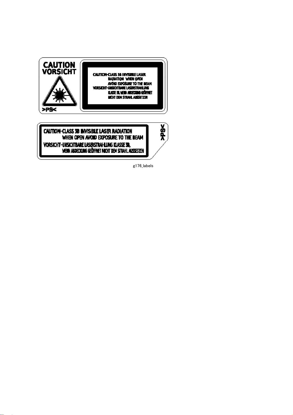
Caution Labels

Conventions
Conventions
Symbol What it means
Refer to section number
See Core Tech Manual for details
Screw
Connector
E-ring
C-ring
The following notations are used in text to describe the direction of paper feed: lengthwise and
sideways. The annotations “SEF” and “LEF” denote “Short Edge Feed” and “Long Edge Feed”.
(The arrows indicate the direction of paper feed.)

PRODUCT INFORMATION
REVISION HISTORY
Page Date Added/Updated/New
None


1. PRODUCT INFORMATION
Specifications
1.1 SPECIFICATIONS
See Appendices:
Appendices: Basic Specifications
Appendices: Controller Specifications
Product
Information
SM 1-1 M020/M021
1.2 MACHINE CONFIGURATION
1.2.1 SYSTEM COMPONENTS
Main
Item Machine code Remarks
Mainframe (45 / 47 ppm) M020
Mainframe (50 / 52 ppm) M021
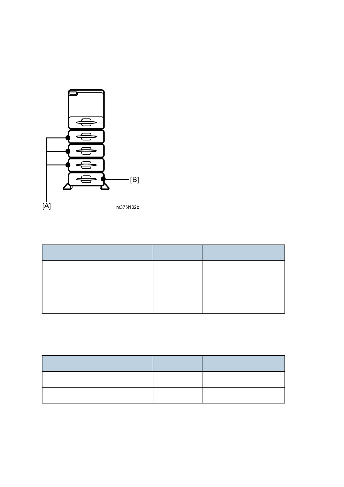
Options
Item Machine code Remarks
45 ppm (A4 - SEF)
47 ppm (LT - SEF)
50 ppm (A4 - SEF)
52 ppm (LT - SEF)
Paper Feed Unit TK1120 [A] M386 Without casters
Paper Feed Unit TK1130 [B] M389 With casters
M020/M021 1-2 SM
Machine Configuration
Product
Information
SM 1-3 M020/M021

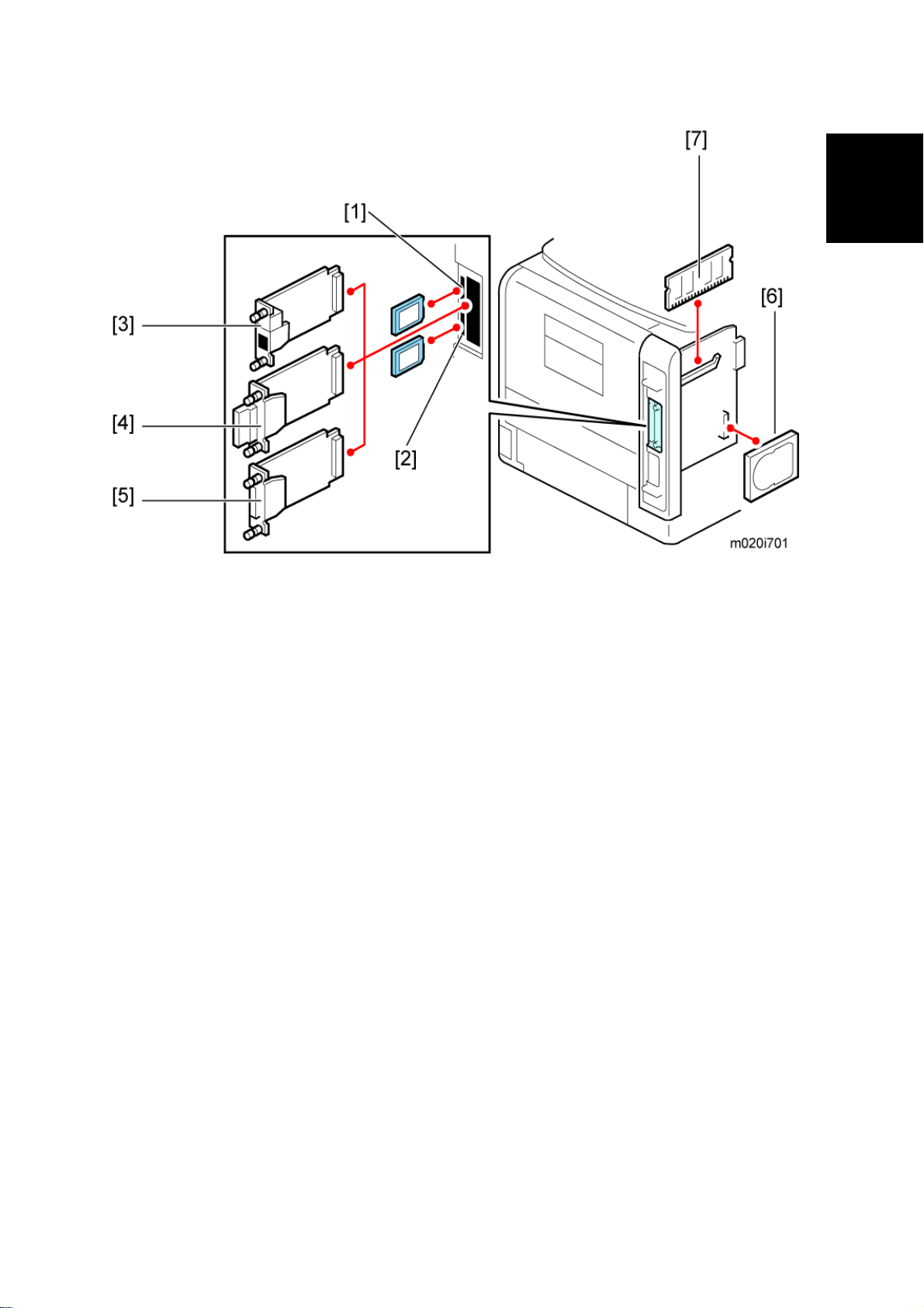
Internal options
Item Machine code Remarks
Memory Unit Type G 256 MB [7] D362 Optional for M020
Memory Unit Type I 512 MB [7] D435 Optional for M020
Hard Disk Drive Type 4310 [6] M394 Optional for M020
IEEE 1284 Interface Board Type A [5] B679
IEEE 802.11a/g interface Unit Type L
[4]
IEEE 802.11a/g Interface Unit Type M
[4]
Gigabit Ethernet Board Type A [3] G874
Gigabit Ethernet Board Type C [3] M397 For NA
SD Card for Netware Printing Type E
[1]
IPDS Unit Type 5200 [1] M388-04 For NA
IPDS Unit Type 5200 [1] M388-05 For EU
SD Card for Fonts Type C [1] M352 For EU
M344 For NA
M344 For EU
M388-03
M020/M021 1-4 SM
1.3 OVERVIEW
Overview
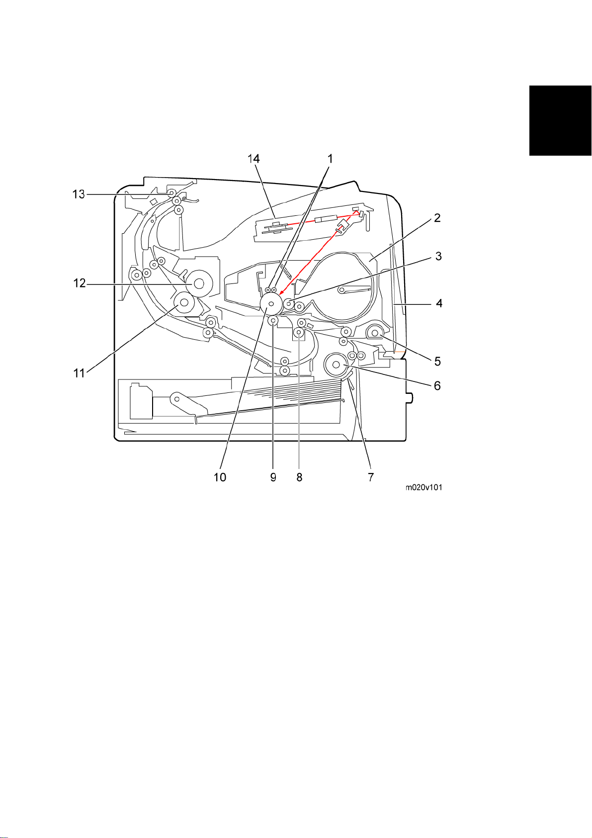
1.3.1 MECHANICAL COMPONENT LAYOUT
Product
Information
1. Charge roller 8. Registration roller
2. Cartridge (AIO-type) 9. Transfer roller
3. Development roller 10. Drum
4. By-pass feed tray 11. Pressure roller
5. By-pass feed roller 12. Hot roller
6. Paper feed roller 13. Paper exit roller
7. Friction pad 14. Laser unit
SM 1-5 M020/M021
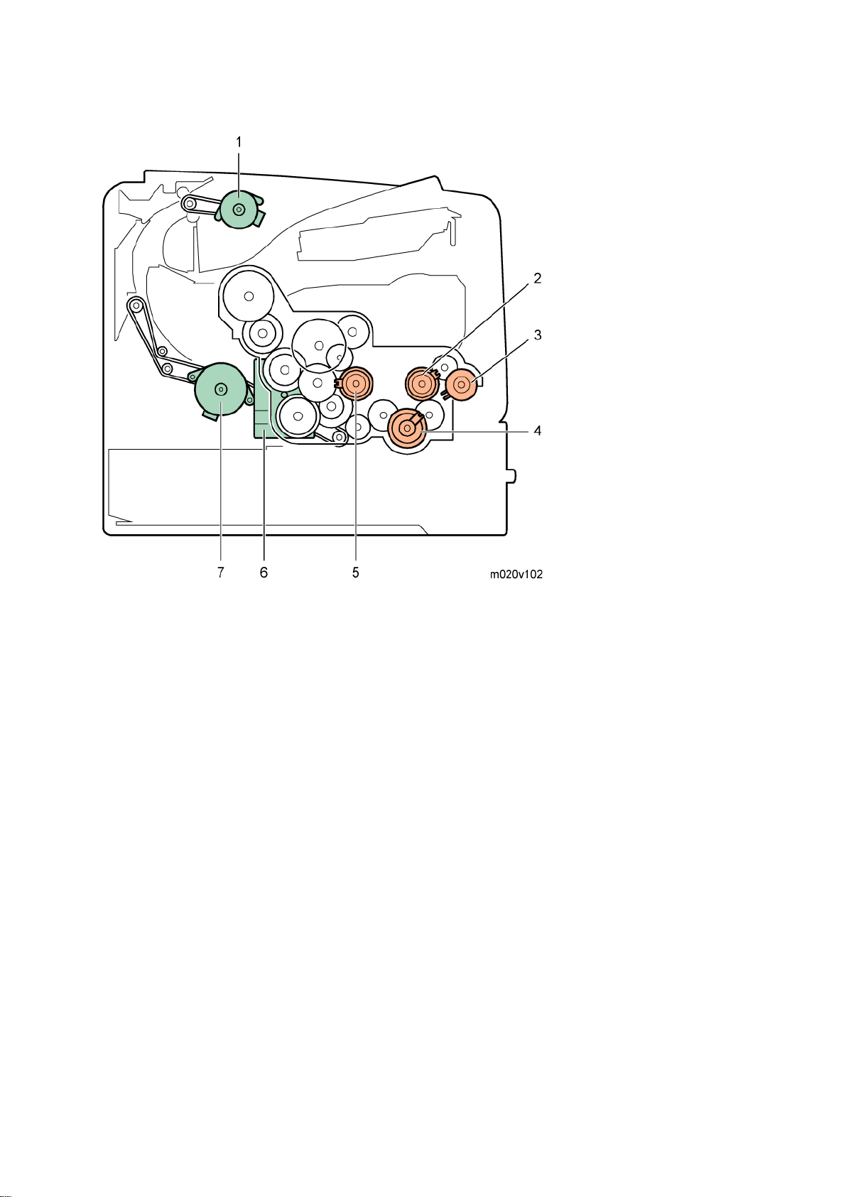
Drive Layout
1. Paper exit motor
2. Relay clutch
3. By-pass feed clutch
4. Paper feed clutch
5. Registration clutch
6. Main motor
7. Duplex motor
M020/M021 1-6 SM

1.3.2 PAPER PATH
Overview
Product
Information
1. Paper feed through duplex unit
2. Paper exit to the paper stack
3. Paper feed from tray 1
4. Paper feed from by-pass tray
5. Paper feed from optional PFU (tray 2)
6. Paper feed from optional PFU (tray 3)
7. Paper feed from optional PFU (tray 4)
8. Paper feed from optional PFU (tray 5)
SM 1-7 M020/M021


INSTALLATION
REVISION HISTORY
Page Date Added/Updated/New
None


2. INSTALLATION
2.1 MACHINE INSTALLATION
Refer to the following sections for installation details for all models.
Category Item Machine code References
Machine Installation
Main unit -
Paper Feed Unit TK1120 M386 p.2-22
Paper Feed Unit TK1130 M389 p.2-27
Memory Unit Type G 256 MB D362
Memory Unit Type I 512 MB D435
Hard Disk Drive Type 4310 M394
IEEE 802.11a/g interface Unit
Type L (NA) *1
IEEE 802.11a/g interface Unit
Options
Type M (EU) *1
IEEE 1284 Interface Board
Type A
M020/
M021
M344
M344
B679
Quick Installation Guide
p.2-4, p.2-5
Installation
Gigabit Ethernet Board Type A
*1
Gigabit Ethernet Board Type C
*1
IPDS Unit Type 5200 D571
SD Card for Netware Printing
Type E
Drivers -
*1: These units cannot be installed at the same time.
SM 2-1 M020/M021
G874
M397
Software Guide,
M388-03
Section 6
Software Guide,
Section 1
Installation Requirements
2.2 INSTALLATION REQUIREMENTS
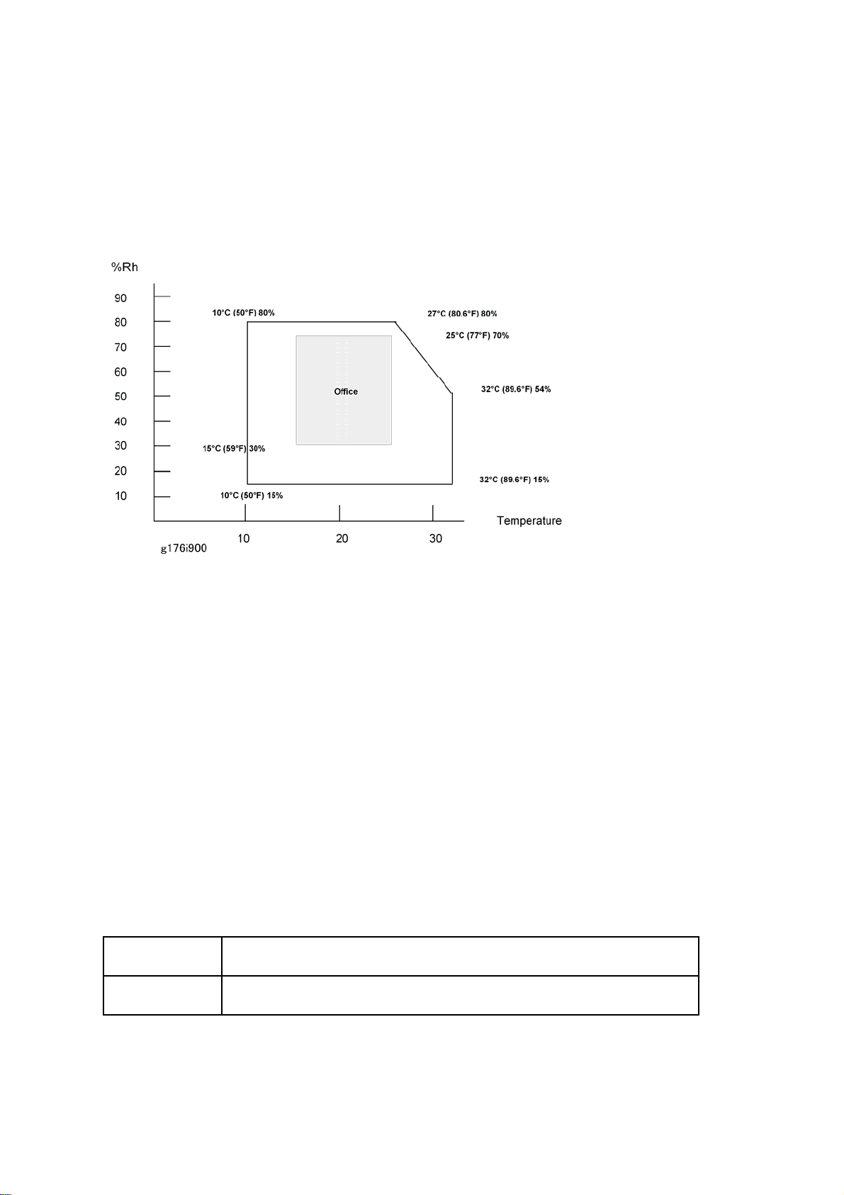
2.2.1 ENVIRONMENT
–Temperature and Humidity Chart–
Temperature Range: 10°C to 32°C (50°F to 89.6°F)
Humidity Range: 15% to 80% RH
Ambient Illumination: Less than 1,500 lux (Do not expose to direct sunlight.)
Ventilation: Room air should turn over at least 3 times/hr/person
3
Ambient Dust: Less than 0.1 mg/m
Do not install the machine where it will be exposed to direct sunlight or to direct airflow
(from a fan, air conditioner, air cleaner, etc.).
Do not install the machine where it will be exposed to corrosive gas.
Install the machine at a location lower than 2,000 m (6,560 ft.) above sea level.
Place the machine on a firm and level base.
Do not install the machine where it may be subjected to strong vibration.
2.2.2 MACHINE LEVEL
Front to back: Within 5 mm (0.2") of level
Right to left: Within 5 mm (0.2") of level
M020/M021 2-2 SM
Installation Requirements
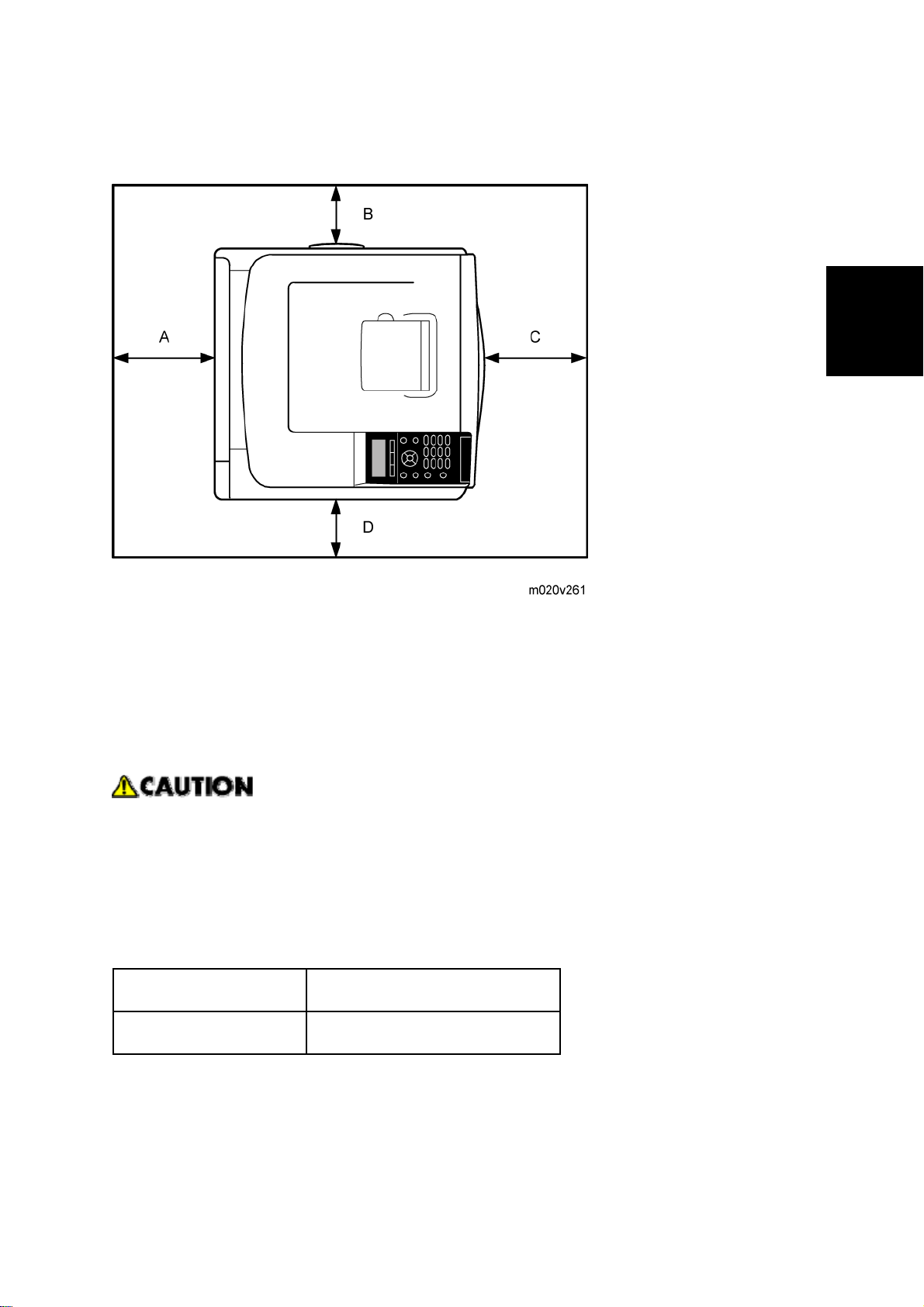
2.2.3 MINIMUM OPERATIONAL SPACE REQUIREMENTS
Place the machine near the power source, providing clearance as shown.
Installation
A: Rear – 200 mm (7.9")
B: Right – 100 mm (4.0")
C: Front – 350 mm (13.8")
D: Left – 100 mm (4.0")
2.2.4 POWER SUPPLY
Make sure that the wall outlet is near the machine and easily accessible. After
completing installation, make sure the plug fits firmly into the outlet.
Avoid multiple connections to the same power outlet.
Be sure to ground the machine.
Input voltage:
North America: 120 – 127 V, 60 Hz, 12 A
Europe/Asia: 220 – 240 V, 50/60 Hz, 8 A
Image quality guaranteed at rated voltage ± 10%.
Operation guaranteed at rated voltage ± 15%.
SM 2-3 M020/M021
Loading...