


 Loading...
User Guide
Selected Version
Getting Started
Web Image Monitor
Adding Paper and Toner
Troubleshooting
Information for This Machine
For information not found in this manual, see the online manuals available on our web site (https://www.ricoh.com/).
For safe and correct use, be sure to read Safety Information before using the machine.

TABLE OF CONTENTS |
|
How to Read This Manuals................................................................................................................................ |
4 |
Symbols Used in This Manuals...................................................................................................................... |
4 |
1. Getting Started |
|
Model-Specific Information............................................................................................................................... |
5 |
Guide to Names and Functions of Components.............................................................................................. |
6 |
Guide to Components.................................................................................................................................... |
6 |
Connecting and Setting the Network............................................................................................................. |
11 |
Setting Wired LAN....................................................................................................................................... |
11 |
Setting Wireless LAN................................................................................................................................... |
13 |
Connecting the USB Interface......................................................................................................................... |
22 |
Connecting to the USB (Type B) Interface................................................................................................. |
22 |
Connecting a Device to the Machine's USB Host Interface..................................................................... |
22 |
Guide to Functions of the Machine's External Options................................................................................. |
24 |
Order of Option Installation............................................................................................................................ |
25 |
Attaching the Paper Feed Unit........................................................................................................................ |
26 |
The number of tray that you can install...................................................................................................... |
27 |
Installing the Hard Disk.................................................................................................................................... |
29 |
Installing the Wireless LAN interface board.................................................................................................. |
34 |
Installing the IEEE 1284 interface board....................................................................................................... |
35 |
Connecting to the IEEE 1284 Interface..................................................................................................... |
36 |
Installing the USB device server...................................................................................................................... |
37 |
Procedure for installing the USB device server.......................................................................................... |
37 |
Connecting to the Extra Ethernet Interface with the USB Device Server Option.................................... |
38 |
Specifying an IP address for the USB Device Server................................................................................ |
40 |
Installing SD Card Options.............................................................................................................................. |
43 |
Guide to the Names and Functions of the Control Panel.............................................................................. |
45 |
Guide to the Names and Functions of the Control Panel Screen................................................................. |
47 |
Turning On/Off the Power.............................................................................................................................. |
48 |
Turning On/Off the Main Power................................................................................................................ |
48 |
Logging In the Machine................................................................................................................................... |
50 |
User Code Authentication Using a Printer Driver...................................................................................... |
50 |
Logging In/Out Using the Control Panel................................................................................................... |
50 |
1

2. Print |
|
Installing the Printer Driver for Network Connection (Windows)................................................................. |
53 |
Installing the PCL 6 Printer Driver from the CD-ROM............................................................................... |
53 |
Installing the Printer Driver for USB Connection (Windows)........................................................................ |
57 |
Installing the Printer Driver from the CD-ROM.......................................................................................... |
57 |
Displaying the Printer Driver Properties.......................................................................................................... |
60 |
Standard Printing.............................................................................................................................................. |
61 |
When Using the PCL 6 Printer Driver.......................................................................................................... |
61 |
Printing on Both Sides of Sheets...................................................................................................................... |
65 |
How to Print on Both Sides of the Paper (When Using the PCL 6 Printer Driver).................................... |
65 |
Combining Multiple Pages into Single Page.................................................................................................. |
66 |
How to Print Multiple Pages onto a Single Sheet (When Using the PCL 6 Printer Driver)..................... |
66 |
Printing on Envelopes....................................................................................................................................... |
68 |
Configuring Envelope Settings Using the Control Panel........................................................................... |
68 |
Printing on Envelopes Using the Printer Driver........................................................................................... |
68 |
3. Web Image Monitor |
|
Displaying Top Page........................................................................................................................................ |
71 |
4. Adding Paper and Toner |
|
Loading Paper.................................................................................................................................................. |
73 |
Loading Paper into Paper Trays.................................................................................................................. |
73 |
Loading Paper into the Bypass Tray........................................................................................................... |
76 |
Loading Orientation-fixed Paper or Two-sided Paper.............................................................................. |
79 |
Recommended Paper....................................................................................................................................... |
81 |
When Loading Thick Paper......................................................................................................................... |
87 |
When Loading Envelopes........................................................................................................................... |
88 |
Adding Toner.................................................................................................................................................... |
90 |
Disposing of Used Print Cartridge.............................................................................................................. |
92 |
5. Troubleshooting |
|
When a Status Icon Is Displayed on the Control Panel................................................................................ |
93 |
When a Panel Tone Beeps.............................................................................................................................. |
94 |
Status Messages............................................................................................................................................... |
95 |
Alert Messages (Displayed on the Control Panel)........................................................................................ |
97 |
Alert Messages (Printed on Error Logs and Reports).................................................................................. |
103 |
2

Cautions in Removing Jammed Paper.......................................................................................................... |
|
|
108 |
Removing Jammed Paper.............................................................................................................................. |
|
|
112 |
Paper Misfeed Message (A1).................................................................................................................. |
|
|
112 |
Paper Misfeed Message (A2).................................................................................................................. |
|
|
114 |
Paper Misfeed Message (B)..................................................................................................................... |
|
|
117 |
Paper Misfeed Message (C).................................................................................................................... |
|
|
120 |
Paper Misfeed Message (Y1) to (Y3)...................................................................................................... |
|
|
123 |
Paper Misfeed Message (Z1).................................................................................................................. |
|
|
125 |
6. Information for This Machine |
|
|
|
ENERGY STAR Program................................................................................................................................ |
|
|
129 |
Energy Saving Functions............................................................................................................................... |
|
|
130 |
User Information on Electrical and Electronic Equipment |
(mainly Europe) |
.......................... 132 |
|
Users in the countries where this symbol shown in this section has been specified in national law on |
|||
collection and treatment of E-waste......................................................................................................... |
|
|
132 |
All Other Users.......................................................................................................................................... |
|
|
132 |
For Users in India....................................................................................................................................... |
|
|
132 |
For Turkey Only......................................................................................................................................... |
|
|
133 |
Note for the Battery and/or Accumulator Symbol (For EU countries only) |
(mainly Europe)..... |
||
......................................................................................................................................................................... |
|
|
134 |
Environmental Advice for Users |
(mainly Europe).................................................................... |
|
135 |
Users in the EU, Switzerland and Norway............................................................................................. |
|
135 |
|
Notes to users in the state of California (Notes to Users in USA) |
(mainly North America). 136 |
||
Specifications for the Main Unit................................................................................................................... |
|
|
137 |
Specifications for Printer................................................................................................................................ |
|
|
141 |
Specifications for Lower Paper Tray (250 sheets)...................................................................................... |
|
143 |
|
Specifications for Lower Paper Tray (500 sheets)...................................................................................... |
|
144 |
|
Specifications for IEEE 1284 Interface Board............................................................................................. |
|
145 |
|
Specifications for Wireless LAN Interface Board........................................................................................ |
|
146 |
|
Specifications for USB Device Server.......................................................................................................... |
|
|
148 |
Copyright Information about Installed Applications................................................................................... |
|
149 |
|
INDEX........................................................................................................................................................... |
|
|
151 |
3

How to Read This Manuals
Symbols Used in This Manuals
This manual uses the following symbols:
Indicates points to pay attention to when using functions. This symbol indicates points that may result in the product or service becoming unusable or result in the loss of data if the instructions are not obeyed. Be sure to read these explanations.
Indicates supplementary explanations of the machine's functions, and instructions on resolving user errors.
Indicates where you can find further relevant information.
[ ]
Indicates the names of keys or buttons on the product or display.


 (mainly Europe and Asia), (mainly Europe), or (mainly Asia)


 (mainly North America)
Differences in the functions of Region A and Region B models are indicated by two symbols. Read the information indicated by the symbol that corresponds to the region of the model you are using. For details about which symbol corresponds to the model you are using, see page 5 "Model-Specific Information" .
.
4

1. Getting Started
This chapter describes how to start using this machine.
Model-Specific Information
This section explains how you can identify the region your machine belongs to.
There is a label on the rear of the machine, located in the position shown below. The label contains details that identify the region your machine belongs to. Read the label.
DYR224 |
The following information is region-specific. Read the information under the symbol that corresponds to the region of your machine.


 (mainly Europe and Asia)
If the label contains the following, your machine is a region A model:
•CODE XXXX -27, -29
•220–240 V


 (mainly North America)
If the label contains the following, your machine is a region B model:
•CODE XXXX -17
•120–127 V
•Dimensions in this manual are given in two units of measure: metric and inch. If your machine is a Region A model, refer to the metric units. If your machine is a Region B model, refer to the inch units.
•If your machine is a region A model and "CODE XXXX -27" is printed on the label, see "


 (mainly Europe)" also.
•If your machine is a region A model and "CODE XXXX -29" is printed on the label, see "


 (mainly Asia)" also.
5

1. Getting Started
Guide to Names and Functions of Components
Guide to Components
•Do not obstruct the machine's vents. Doing so risks fire caused by overheated internal components.
Front and right view
13 |
|
|
1 |
2 |
3 |
12 |
|
|
11 |
|
|
|
|
4 |
10 |
|
|
9 |
|
5 |
8 |
|
4 |
|
|
|
7 |
|
6 |
|
|
|
|
|
DYR151 |
1.Stop fence
Open this fence to prevent paper from falling off.
2.Standard tray
Output is stacked here with the print side down.
3.Control panel
See page 45 "Guide to the Names and Functions of the Control Panel".
4.Ventilation holes
Prevent overheating.
6

Guide to Names and Functions of Components
5.Memory cover
Open to install a hard disk.
6.Front cover open button
Push this button to open the front cover.
7.Lower paper trays
Load paper here.
For details, see page 24 "Guide to Functions of the Machine's External Options".
8.Tray 1
Load paper here.
9.Front cover
Open to access the inside of the machine and remove jammed paper. Open here to replace the print cartridge and the drum unit.
10.Main power switch
To operate the machine, the main power switch must be on. If it is off, turn the switch on. See page 48 "Turning On/Off the Power".
11.Bypass tray
Use to print on thick paper, OHP transparencies, envelopes, and label paper (adhesive labels).
12.Extender for the bypass tray
Pull this extender out when loading A4 , 81/2 × 11
 or larger size paper in the bypass tray.
13.Paper guides
When loading paper in the bypass tray, align the paper guides flush against the paper.
7
1. Getting Started
Rear and left view
9 |
|
|
|
|
8 |
|
|
|
|
7 |
|
|
|
|
6 |
|
|
|
|
5 |
|
|
|
|
4 |
1 |
3 |
2 |
1 |
DYR156
1.Vents
Prevent overheating.
2.Power connector
Connect the power cord to the machine. Insert the other end into an electrical outlet.
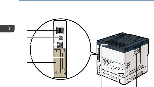
3.Rear cover
Open to access the inside of the machine and remove jammed paper. Open here to replace the fusing unit.
4.Rear cover open lever
Pull this lever to open the rear cover.
5.Slot
Optional interface boards can be inserted.
6.Expansion card slots
Remove the cover to install SD cards.
7.Ethernet port
Use a network interface cable to connect the machine to a network.
8.USB 2.0 [Type B] port
Use a USB cable to connect the machine to a computer.
9.USB Host Interface
Connect external devices such as a card authentication device.
8
Guide to Names and Functions of Components
Interior: Front view
1 2
DYR153
1.Print cartridge
To remove jammed paper, pull out the Print cartridge and drum unit as a single unit.
Messages appear on the screen when the print cartridge needs to be replaced, or a new cartridge needs to be prepared.
For details about the messages that appear on the screen when consumables need to be replaced, see "Adding Toner", Maintenance.
When you remove jammed paper, pull out the print cartridge with the drum unit. If you want to remove only the print cartridge, pull down the lever on the left side of the print cartridge, and then pull the print cartridge out.
2.Drum unit
Messages appear on the screen when the drum unit needs to be replaced, or a new drum unit needs to be prepared.
For details about the messages that appear on the screen when consumables need to be replaced, see "Replacing the Drum Unit", Maintenance.
For P502:
When the drum unit needs to be replaced, contact your service representative.
9

1. Getting Started
Interior: Rear view
1
DYR154
1.Fusing unit
Pull out the fusing unit and remove jammed paper.
Messages appear on the screen when the fusing unit needs to be replaced, or a new fusing unit needs to be prepared.
For details about the messages that appear on the screen when consumables need to be replaced, see "Replacing the Maintenance Kit", Maintenance.
For P502:
When the fusing unit needs to be replaced, contact your service representative.
10

Connecting and Setting the Network
Connecting and Setting the Network
Setting Wired LAN
Connecting Ethernet Interface
This section describes how to connect an Ethernet interface cable to the Ethernet port.
If you use an Ethernet interface cable that supports 1000BASE-T, set [Ethernet Speed] to [Auto Select: Enable 1Gbps] in [Network] in [Host Interface].
•Use the following Ethernet cables.
•When using 100BASE-TX/10BASE-T:
Unshielded Twisted Pair Cable (UTP) or Shielded Twisted Pair Cable (STP) and Category type 5 or more
•When using 1000BASE-T:
Unshielded Twisted Pair Cable (UTP) or Shielded Twisted Pair Cable (STP) and Category type 5e or more
•When you use IPv6, set [IPv6] to [Active] in [Effective Protocol] in [Network] of [Host Interface]. IPv6 is inactive as a factory default. When you enable IPv6, a link-local address is automatically set.
•When you use IPv6, consult your network administrator.
1.Make sure the main power is switched off.
2.Connect the Ethernet interface cable to the Ethernet port.
DYR209 |
3.Connect the other end of the Ethernet interface cable to a network connection device such as a hub.
11

1.Getting Started
4.Turn on the main power switch of the machine.
1
3 
2
DRS703
1.Indicator (orange)
When 100BASE-TX is operating, the LED is lit orange.
2.Indicator (green)
When 10BASE-T is operating, the LED is lit green.
3.Indicators (both orange and green)
When 1000BASE-T is operating, both LEDs are lit.
•When Energy Saver mode is enabled, the LEDs may not light up.
Obtaining an IP address automatically (IPv4 DHCP)
The machine is set to obtain IP addresses automatically as a factory default.
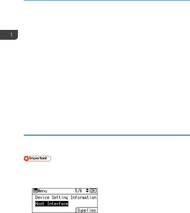
1.Press the [Menu] key.
2.Press the [ ] or [
 ] key to select [Host Interface], and then press the [OK] key.
3.Press the [ ] or [
 ] key to select [Network], and then press the [OK] key.
4.Press the [ ] or [
 ] key to select [Machine IPv4 Address], and then press the [OK] key.
5.Press the [ ] or [
 ] key to select [Auto-Obtain (DHCP)], and then press the [OK] key. Specifying an IP address (IPv4)
1. Press the [Menu] key.
12

Connecting and Setting the Network
2.Press the [ ] or [
 ] key to select [Host Interface], and then press the [OK] key.
3.Press the [ ] or [
 ] key to select [Network], and then press the [OK] key.
4.Press the [ ] or [
 ] key to select [Machine IPv4 Address], and then press the [OK] key.
5.Press the [ ] or [
 ] key to select [Specify], and then press the [OK] key.
6.Press the selection key beneath [IP Add.], and then enter the IP address.
7.Press the [OK] key.
8.Press the selection key beneath [Subnet M], and then enter the subnet mask.
9.Press the [OK] key.
10.Press the selection key beneath [Gateway], and then enter the gateway.
11.Press the [OK] key.
12.Confirm the [Specify] is selected, and then press the [OK] key.
13.Press the [Escape] key.
Setting Wireless LAN
Wireless LAN connection is available when you install the optional Wireless LAN interface board.
See page 34 "Installing the Wireless LAN interface board" for how to install the Wireless LAN interface board.
Selecting the communication mode for the Wireless LAN
Select the communication mode according to your environment.
13

1. Getting Started
How to select the mode
Which wireless LAN environment are you using?
A wireless LAN 
 router is being used.

A wireless LAN router is not being used.
Do you know how to specify the SSID*1 or the password for connecting your device to a network?
Yes |
No |
Infrastructure |
Wireless Direct |
Wireless Direct Mode |
|
Group Owner Mode |
|||
|
|
DVL258
*1 SSID is an identifier to distinguish Wireless LAN networks. It is also called a "Network name" or "Access point name".
You can also connect via Ad hoc mode. For detailed information, see the explanation for each mode.
About the modes
Mode |
|
Description |
|
|
In infrastructure mode, you can connect |
Infrastructure Mode |
|
several devices and the machine via a wireless |
|
LAN router. |
|
|
|
|
|
|
You can also print data on a network, such as |
|
|
a website, even when a device is connected. |
|
DYR230 |
The machine's communication mode is set to |
|
|
infrastructure mode as a factory default. |
14

|
|
Connecting and Setting the Network |
|
|
Mode |
Description |
|
|
|
In Wireless Direct Mode, you can connect the |
|
|
|
machine and a device without using a wireless |
|
Wireless Direct Mode |
LAN router. |
||
|
|||
• |
Wireless Direct Group Owner Mode |
There are two types of connection methods in |
|
Wireless Direct mode. |
|||
|
|
||
|
|
• Wireless Direct Group Owner Mode |
|
|
|
You can connect several devices, including |
|
|
|
devices that are not compliant with Wi-Fi |
|
|
|
Direct. You need to enter the SSID and |
|
|
|
password of the machine on the device you |
|
|
|
want to connect. |
|
|
|
• Wireless Direct |
|
|
DYR231 |
You can connect the machine and a device |
|
|
|
||
• |
Wireless Direct |
directly to each other. |
|
|
|
Select the machine from the device you want to |
|
|
|
connect. |
|
|
|
Only devices that are Android 4.0 or later and |
|
|
DVK543 |
support Wi-Fi Direct can be connected. |
|
|
|
You cannot print data on a network, such as a |
|
|
|
website, when a device is connected. |
|
Ad-hoc Mode |
You need to set the ad-hoc channel and other |
||
|
|
settings, on the device you are connecting. |
|
|
|
You cannot select WPA2 as the security |
|
|
|
method. You cannot print data on a network, |
|
|
DYR232 |
such as a website, when a device is connected. |
|
Procedure for the settings
For Ad hoc Mode, see page 16 "Connecting in Ad hoc Mode".
For Infrastructure Mode, see page 17 "Connecting in Infrastructure Mode".
For Direct Connection Mode, see page 19 "Connecting in Direct Connection Mode".
For Direct Connection Group Owner Mode, see page 20 "Connecting in Direct Connection Group Owner Mode".
15

1. Getting Started
Connecting in Ad hoc Mode
In Ad hoc mode, you can specify an SSID to the machine, and connect your computer directly to the machine via a wireless LAN.
• The Wireless LAN interface board must be installed to use Ad hoc mode.
1.Press the [Menu] key.
2.Press the [ ] or [
 ] key to select [Host Interface], and then press the [OK] key.
3.Press the [ ] or [
 ] key to select [Network], and then press the [OK] key.
4.Press the [ ] or [
 ] key to select [LAN Type], and then press the [OK] key.
5.Press the [ ] or [
 ] key to select [Wireless LAN], and then press the [OK] key.
6.Press the [Escape] key.
7.Press the [ ] or [
 ] key to select [Wireless LAN], and then press the [OK] key.
8.Press the [ ] or [
 ] key to select [Communication Mode], and then press the [OK] key.
9.Press the [ ] or [
 ] key to select [802.11 Ad-hoc Mode], and then press the [OK] key.
10.Press the [ ] or [
 ] key to select [SSID Setting], and then press the [OK] key.
11.Press the selection key beneath [Enter SSID].
12.Press the selection key beneath [Enter].
13.Press the [ ], [
], [ ], [
], [ ] or [
 ] key to select a character, and then press the [OK] key to enter the SSID.
14.Press the selection key beneath [Accept] when you finish entering the SSID.
15.Press the [ ] or [
 ] key to select [Ad-hoc Channel], and then press the [OK] key.
16.Press the [ ], [
], [ ], [
], [ ] or [
 ] key to select a channel, and then press the [OK] key.
17.Press the [ ] or [
 ] key to select [Security Method], and then press the [OK] key.
18.Press the [ ] or [
 ] key to select [WEP], and then press the selection key beneath [Details].
To not use security setting, select [No].
19.Press the selection key beneath [Enter].
20.Press the [ ], [
], [ ], [
], [ ] or [
 ] key to select a character, and then press the [OK] key to enter the WEP key.
21.Press the selection key beneath [Accept].
16

Connecting and Setting the Network
22. Press the [ ] or [
 ] key to select [WEP], and then press the [OK] key.
The settings are complete.
You can connect the device in Ad hoc mode by specifying the SSID, channel, and security method that are specified for the machine.
See the instructions supplied with the device for how to connect it in ad hoc mode.
Connecting in Infrastructure Mode
Use infrastructure mode to connect the machine to an access point.
•The Wireless LAN interface board must be installed to use Infrastructure mode.
•When you use IPv6, set [IPv6] to [Active] in [Effective Protocol] in [Network] of [Host Interface]. IPv6 is inactive as a factory default. When you enable IPv6, a link-local address is automatically set.
•When you use IPv6, consult your network administrator.
1.Press the [Menu] key.
2.Press the [ ] or [
 ] key to select [Host Interface], and then press the [OK] key.
3.Press the [ ] or [
 ] key to select [Network], and then press the [OK] key.
4.Press the [ ] or [
 ] key to select [LAN Type], and then press the [OK] key.
5.Press the [ ] or [
 ] key to select [Wireless LAN], and then press the [OK] key.
6.Press the [Escape] key.
7.Press the [ ] or [
 ] key to select [Wireless LAN], and then press the [OK] key.
8.Press the [ ] or [
 ] key to select [Communication Mode], and then press the [OK] key.
9.Press the [ ] or [
 ] key to select [Infrastructure Mode], and then press the [OK]
10.Press the [ ] or [
 ] key to select [SSID Setting], and then press the [OK]
11.Press the selection key beneath [SSID].
12.Press the selection key beneath [Enter].
13.Press the [ ], [
], [ ], [
], [ ] or [
 ] key to select a character, and then press the [OK] key to enter the SSID that you want to connect to.
14.Press the selection key beneath [Accept] when you finish entering the SSID.
15.Press the [ ] or [
 ] key to select [Security Method], and then press the [OK] key.
17

1.Getting Started
16.Press the [ ] or [
 ] key to select the security method that is specified for the access point you want to connect to.
17.Press the selection key beneath [Enter].
Select [WEP] or [WPA2], and then press the selection key beneath [Details] to enter your password.
If you do not use security setting, select [No]. The settings are complete.
To check the connection status, enter [Wireless LAN Signal] in [Wireless LAN] and confirm the signal status.
Obtaining an IP address automatically (IPv4 DHCP)
The machine is set to obtain IP addresses automatically as a factory default.
1.Press the [Menu] key.
2.Press the [ ] or [
 ] key to select [Host Interface], and then press the [OK] key.
3.Press the [ ] or [
 ] key to select [Network], and then press the [OK] key.
4.Press the [ ] or [
 ] key to select [Machine IPv4 Address], and then press the [OK] key.
5.Press the [ ] or [
 ] key to select [Auto-Obtain (DHCP)], and then press the [OK] key. Specifying an IP address (IPv4)
1.Press the [Menu] key.
2.Press the [ ] or [
 ] key to select [Host Interface], and then press the [OK] key.
3.Press the [ ] or [
 ] key to select [Network], and then press the [OK] key.
4.Press the [ ] or [
 ] key to select [Machine IPv4 Address], and then press the [OK] key.
5.Press the [ ] or [
 ] key to select [Specify], and then press the [OK] key.
6.Press the selection key beneath [IP Add.], and then enter the IP address.
7.Press the [OK] key.
18
Connecting and Setting the Network
8.Press the selection key beneath [Subnet M], and then enter the subnet mask.
9.Press the [OK] key.
10.Press the selection key beneath [Gateway], and then enter the gateway.
11.Press the [OK] key.
12.Confirm the [Specify] is selected, and then press the [OK] key.
13.Press the [Escape] key.
Connecting in Direct Connection Mode
To connect another device and the machine directly using the wireless direct function, use the Wireless Direct mode.
• The Wireless LAN interface board must be installed to use Wireless Direct mode.
1.Press the [Menu] key.
2.Press the [ ] or [
 ] key to select [Host Interface], and then press the [OK] key.
3.Press the [ ] or [
 ] key to select [Direct Connection], and then press the [OK] key.
4.Press the [ ] or [
 ] key to select [Active/Inactive], and then press the [OK] key.
5.Press the [ ] or [
 ] key to select [Active], and then press the [OK] key.
6.Press the [Escape] key.
7.Press the [ ] or [
 ] key to select [Network], and then press the [OK] key.
8.Press the [ ] or [
 ] key to select [LAN Type], and then press the [OK] key.
9.Press the [ ] or [
 ] key to select [Wireless LAN], and then press the [OK] key.
10.Press the [Escape] key.
11.Press the [ ] or [
 ] key to select [Wireless LAN], and then press the [OK] key.
12.Press the [ ] or [
 ] key to select [Communication Mode], and then press the [OK] key.
13.Press the [ ] or [
 ] key to select [Direct Connection Mode], and then press the [OK] key.
14.Press the [ ] or [
 ] key to select [Direct Connection Settings], and then press the [OK] key.
15.Press the [ ] or [
 ] key to select [Device Name], and then press the [OK] key.
16.Press the selection key beneath [Enter].
19
1.Getting Started
17.Press the [ ], [
], [ ], [
], [ ] or [
 ] key to select a character, and then press the [OK] key to enter the device name.
18.Press the selection key beneath [Accept] when you finish entering the device name.
19. Press the [ ] or [
 ] key to select [Connection Password], and then press the [OK] key.
20.Press the selection key beneath [Enter].
21.Press the [ ], [
], [ ], [
], [ ] or [
 ] key to select a character, and then press the [OK] key to enter the connection password.
22.Press the selection key beneath [Accept] when you finish entering the connection password.
23.Press the [ ] or [
 ] key to select [WLAN: EasySetup/Direct Con], and then press the [OK] key.
24.Press the [ ] or [
 ] key to select [Push Button Method], and then press the [OK] key.
25.Press the selection key beneath [Start].
The settings are complete.
Operate the push buttons on the device that you want to connect.
See the instructions supplied for the device for how to connect it in Wireless Direct mode.
Connecting in Direct Connection Group Owner Mode
To connect to multiple wireless direct-compliant devices by using the machine as a simple access point, use the Direct Connection Group Owner mode. Up to nine devices can be connected. Non-wireless direct-compliant devices can be connected too.
• The Wireless LAN interface board must be installed to use Wireless Direct Group Owner mode.
1.Press the [Menu] key.
2.Press the [ ] or [
 ] key to select [Host Interface], and then press the [OK] key.
3.Press the [ ] or [
 ] key to select [Direct Connection], and then press the [OK] key.
4.Press the [ ] or [
 ] key to select [Active/Inactive], and then press the [OK] key.
5.Press the [ ] or [
 ] key to select [Active], and then press the [OK] key.
6.Press the [Escape] key.
7.Press the [ ] or [
 ] key to select [Network], and then press the [OK] key.
20

Connecting and Setting the Network
8.Press the [ ] or [
 ] key to select [LAN Type], and then press the [OK] key.
9.Press the [ ] or [
 ] key to select [Wireless LAN], and then press the [OK] key.
10.Press the [Escape] key.
11. Press the [ ] or [
 ] key to select [Wireless LAN], and then press the [OK] key.
12.Press the [ ] or [
 ] key to select [Communication Mode], and then press the [OK] key.
13.Press the [ ] or [
 ] key to select [Dir Con: Group Owner Mode], and then press the [OK] key.
14.Press the [ ] or [
 ] key to select [Direct Connection Settings], and then press the [OK] key.
15.Press the [ ] or [
 ] key to select [Device Name], and then press the [OK] key.
16.Press the selection key beneath [Enter].
17.Press the [ ], [
], [ ], [
], [ ] or [
 ] key to select a character, and then press the [OK] key to enter the device name.
18.Press the selection key beneath [Accept] when you finish entering the device name.
19.Press the [ ] or [
 ] key to select [Connection Password], and then press the [OK] key.
20.Press the selection key beneath [Enter].
21.Press the [ ], [
], [ ], [
], [ ] or [
 ] key to select a character, and then press the [OK] key to enter the connection password.
22.Press the selection key beneath [Accept] when you finish entering the connection password.
23.Press the [ ] or [
 ] key to select [WLAN:EasySetup/Direct Con], and then press the [OK] key.
24.Press the [ ] or [
 ] key to select [Push Button Method], and then press the [OK] key.
25.Press the selection key beneath [Start].
The settings are complete.
Operate the push buttons on the device that you want to connect.
See the instructions supplied for the device for how to connect it by Wireless Direct mode.
21

1. Getting Started
Connecting the USB Interface
Connecting to the USB (Type B) Interface
This section describes how to connect a USB 2.0 (Type B) interface cable to the USB 2.0 port on the machine.
This machine does not come with a USB interface cable. Make sure you purchase the appropriate cable for the machine (connector shape) and your computer.
Use a five meter (197 inch) or shorter cable which supports USB2.0 (Type B) interface.
1. Connect a USB2.0 (Type B) interface cable to the USB2.0 port.
DYR210 |
Connecting a Device to the Machine's USB Host Interface
This section explains how to connect a device to the machine's USB host interface.
This machine does not come with a USB interface cable. Make sure you purchase the appropriate cable for the machine (connector shape) and the device.
Use a five meter (197 inch) or shorter cable which supports USB Host Interface.
•Connect any of the following devices to the USB 2.0 interface: Digital camera, USB keyboards, and IC card readers. Connecting other devices may cause a malfunction.
22

Connecting the USB Interface
1.Connect one end of the USB interface device to the machine's USB host interface.
If you are using a USB interface cable, connect the other end of it to a device such as card authentication one.
DYR211 |
23

1. Getting Started
Guide to Functions of the Machine's External Options
 1
1

 2
2
DYR155
1.Lower paper trays
You can attach up to three lower paper trays.
There are two types of trays, each holding up to 250 or 500 sheets of paper. These trays can be used in any combination.
A customer engineer may be required to install this, depending on the number of levels being installed. Contact your authorized service representative. For details, see "Attaching the Paper Feed Unit", Setup.
2.Caster Table
A table with casters to place this machine.
24

Order of Option Installation
Order of Option Installation
When installing multiple options, the following order is recommended:
1.Attach the Lower paper tray (250 sheets) and the Lower paper tray (500 sheets).
You can attach up to three paper feed units by any combination.
2.Install the Hard disk.
Install the Hard disk to the install area of the controller board.
3.Install the interface board.
Install in the slot of the controller board. Only one interface board can be installed.
4.Insert SD card.
Insert in the SD card slot of the controller board. There are two slots for SD cards.
Each slot supports different types of SD cards.
If you want to use two or more SD cards that can be inserted in the same slot, contact your sales or service representative.
25
1. Getting Started
Attaching the Paper Feed Unit
•It is dangerous to handle the power cord plug with wet hands. Doing so could result in electric shock.
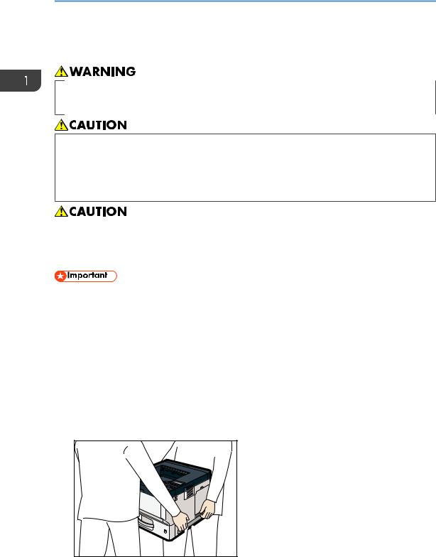
•The machine weighs approximately 19.3 kg (42.6 lb.) (Main unit only, including consumables.)
•When moving the machine, use the inset grips on both sides, and lift slowly. The machine will break or cause injury if dropped.
•Lifting the paper feed unit carelessly or dropping may cause injury.
•Unplug the power cord from the wall outlet before you move the machine. While moving the machine, take care that the power cord is not damaged under the machine. Failing to take these precautions could result in fire or electric shock.
•Do not place the machine directly on the floor.
•When attaching multiple options, attach the paper feed unit first.
•To attach two paper feed units at the same time, first stack them one upon the other, and then attach them as a single unit.
•Before turning on the power, remove the packaging material from the paper feed unit.
1.Check the contents of the package.
2.Turn the machine off and unplug the power cord.
3.Remove the packaging from the paper feed unit.
4.Lift the machine using the inset grips on both sides of the machine.
DYR201
26

Attaching the Paper Feed Unit
When moving the machine, do not hold on the following parts as doing so could cause a malfunction:
•The handle onto the standard paper feed tray
•The underside of the bypass tray
5.There are three upright pins on the optional paper feed unit. Align them with the holes on the underside of the machine, and then carefully lower the machine.
DYR212
6.Plug in the power cord, and then turn on the machine.
7.Print the configuration page to confirm that the unit was attached correctly.
The number of tray that you can install
|
Use on table: printer and one or two optional |
Use on table: printer |
|||||||||||||||||
Person who install |
and three optional |
||||||||||||||||||
|
|
|
paper feed units |
||||||||||||||||
|
|
|
|
paper feed units *1 |
|||||||||||||||
|
|
|
|
|
|
|
|
|
|
|
|
|
|||||||
|
|
|
|
|
|
|
|
|
|
|
|
|
|
|
|
|
|
|
|
|
|
|
|
|
|
|
|
|
|
|
|
|
|
|
|
|
|
|
|
|
|
|
|
|
|
|
|
|
|
|
|
|
|
|
|
|
|
|
|
|
|
|
|
|
|
|
|
|
|
|
|
|
|
|
|
|
|
|
|
|
|
|
|
|
|
|
|
|
|
|
|
|
|
|
|
|
|
|
|
|
|
|
|
|
|
|
|
|
|
|
|
|
|
|
|
|
|
|
|
|
|
|
|
|
|
|
|
|
|
|
|
|
|
|
|
|
|
|
|
|
|
|
|
|
|
|
|
|
|
|
|
|
|
|
|
|
|
|
|
|
|
|
|
|
|
|
|
|
|
|
|
|
|
|
|
|
|
|
|
|
|
|
|
|
|
|
|
|
|
|
|
|
|
|
|
|
|
|
|
|
|
|
|
|
|
|
|
|
|
|
|
|
|
|
|
|
|
|
|
|
|
|
|
|
|
|
|
|
|
|
|
|
|
|
|
|
|
|
|
|
|
|
|
|
|
|
|
|
|
|
|
|
|
|
|
|
|
|
|
|
|
|
|
|
|
|
|
|
|
|
|
|
|
|
|
|
|
|
|
|
|
|
|
|
|
|
|
|
|
|
|
|
|
|
|
|
|
|
|
User
27

1. Getting Started
|
Use on table: printer and one or two optional |
Use on table: printer |
|
Person who install |
and three optional |
||
paper feed units |
|||
|
paper feed units *1 |
||
|
|
Customer engineer
*1 A caster table is required to install three paper feed units on a machine.
28
Loading...