

Page 1
Owner’s Manual
Mobile Trunk-Tracking Scanner
Please read before using this equipment.
A
Cat. No. 20-196
PRO-2067 500-Channel
Page 2

INTRODUCTION
Your new RadioShack 500-Channel
Mobile Trunk-Tracking Scanner is one
of a new generation of scanners designed to track Motorola Type I,
Type II (such as Smartnet and Privacy Plus), GE/Ericsson EDACS, E.F.
Johnson LTR, and hybrid analog
trunking systems, which are extensively used in many 800 MHz, 900
MHz and UHF communication systems.
Trunking communications systems let
a large group of 2-way radio users (or
even different groups of 2-way radio
users) efficiently use a group of frequencies. Instead of selecting a specific frequency for a transmission, the
2-way radio user simply selects a talk
group. The trunking system automatically transmits the call on the first
available frequency, and also sends a
code that uniquely identifies that 2way radio user’s transmission on a different frequency called a data channel.
Since the trunking system might send
individual 2-way radio user’s calls and
response transmissions on different
frequencies, it is difficult to listen to
trunked communications using a regular scanner. The scanner monitors the
data channel frequency sent with a 2way radio user’s transmission and instantly switches to an active frequency, so you can hear the call and
response for that 2-way radio user
and easily “follow” the conversation.
The scanner also lets you scan conventional transmissions, and is preprogrammed with service-search
banks for convenience. By pressing a
single button, you can quickly search
those frequencies most commonly
used by public service and other
agencies without tedious and complicated programming.
This scanner gives you direct access
to over 33,000 frequencies, including
those used by police and fire departments, ambulance services, and amateur radio services, and you can
change your selection at any time.
FEATURES
Your scanner also has these special
features:
Ten Channel-Storage Banks
you store 50 channels in each bank
(500 total channels), letting you group
channels so you can more easily identify calls.
Flexible Operation
— you can track
Motorola, GE/Ericsson, and E.F.
Johnson LTR trunking systems (used
by most trunking communications systems), letting you hear more calls than
many standard trunking scanners.
— let
©
2000 RadioShack Corporation.
RadioShack, RadioShack.com, HyperSearch, and HyperScan are trademarks
All Rights Reserved.
used by RadioShack Corporation.
2
Page 3

Simultaneous Trunking Operation
— you can scan all 3 types of trunking
systems, and both trunking and conventional frequencies, at the same
time.
Text Input
the name of the service you are listening to so the service name appears
when you scan it, making it easier to
identify transmissions.
Digital Weather Alert
weather event text so you can see the
reason for the alert.
Note:
the actual location referenced by
SAME messages. It uses only the
message portion of the SAME signal.
Ten Preprogrammed Frequency
Ranges
missions within preset frequency
ranges or within ranges you set, to reduce search time and select interesting frequencies more quickly.
Private/Digital Private Line Receiving
— decodes and displays the Continuous Tone Coded Squelch System
(CTCSS) and Digital Coded Squelch
(DCS) tone signal being transmitted,
letting you see if the transmitter provides these services.
12-Character, 4-Line, Dot-Matrix
Display
change displayed information.
— you can manually enter
— displays the
The scanner does not display
— let you search for trans-
— makes it easy to view and
Clone/Remote PC Function
you transfer programmed data d ir ectly
to another Cat. No. 20-196 or Cat. No.
20-522 scanner. You can also upload
or download the programmed data to
or from a PC using an optional interface kit.
Triple-Conversion Circuitry
ally eliminates any interference from
IF (intermediate frequency) images,
so you hear only the selected frequency.
Scan Delay
about 2 seconds before moving to another channel, so you can hear more
replies that are made on the same
channel.
Lock-Out Function
your scanner to skip over specified
channels or frequencies when scanning or searching, and skip over IDs
when tracking trunked systems.
Priority Channel
one channel as the priority channel.
As the scanner scans it checks the priority channel every 2 seconds so you
don't miss transmissions on that channel.
ATT (Attenuate) Button
program each memory location to reduce the scanner’s sensitivity to
strong local signals, to reduce interference or noise caused by these signals.
— delays scanning for
— lets you set
— lets you program
— lets
— virtu-
— lets you
Frequency Coverage to 960 MHz
provides a wide range of frequencies
you can listen to.
—
3
Page 4

HyperSearch and HyperScan
—
let you set the scanner to search at up
to 50 steps per second and scan at up
to 25 channels per second, to help
you quickly find interesting transmissions.
DIN-E Size Cabinet
Your scanner can receive these
bands:
Frequency
Range (MHz)
29–54 10-Meter Ham, VHF
Types of
Transmissions
Lo, 6-Meter Ham
Supplied Frequency Guide
— lists
the frequencies for many of the public
safety systems you can listen to.
Memory Backup
— keeps the channel frequencies stored in memory for
an extended time even without batte ry
power.
108–136.9875 Aircraft
137–174 Military Land Mobile,
2-Meter Ham, VHF
Hi
380–512 Federal Govern-
ment, 70-cm Ham
Band, UHF Standard Band, UHF “T”
Band
806–823.9875
849–868.9875
894–960
Public Service “800”
except Cellular
Band
This Owner’s Manual also includes
the section “A General Guide to Scanning” on Page 44 to help you target
frequency ranges in your service area
so you can search for a wide variety of
transmissions.
Note:
See “Specifications” on Page 54
for more information about the scanner’s frequency steps.
4
Page 5

FCC NOTICE
Your scanner might cause radio or TV
interference even when it is operating
properly. To determine whether your
scanner is causing the interference,
turn off your scanner. If the interference goes away, your scanner is
causing it. Try the following methods
to eliminate the interference:
• Move your scanner away from the
receiver.
• Connect your scanner to an outlet
that is on a different electrical circuit from the receiver.
• Contact your local RadioShack
store for help.
This device complies with Part 15 of
FCC Rules
the
the following two conditions: (1) this
device may not cause harmful interference, and (2) this device must accept
any interference received, including
interference that may cause undesired
operation.
Note:
Mobile use of this scanner is
unlawful or requires a permit in some
areas. Check the laws in your area.
. Operation is subject to
SCANNING LEGALLY
Your scanner covers frequencies
used by many different groups including police and fire departments, ambulance services, government agencies,
private companies, amateur radio ser-
vices, military operations, pager services, and wireline (telephone and
telegraph) service providers. It is legal
to listen to almost every transmission
your scanner can receive. However,
there are some transmissions you
should never intentionally listen to.
These include:
• telephone conversations (cellular,
cordless, or other private means
of telephone signal transmission)
• pager transmissions
• any scrambled or encrypted transmissions
According to the Electronic Communications Privacy Act (ECPA), you are
subject to fines and possible imprisonment for intentionally listening to, using, or divulging the contents of such a
transmission unless you have the consent of a party to the communication
(unless such activity is otherwise illegal).
This scanner is designed to prevent
reception of illegal transmissions, in
compliance with the law which requires that scanners be manufactured
in such a way as to not be easily modifiable to pick up those transmissions.
Do not open your scanner's case to
make any modifications that could allow it to pick up transmissions that it is
not legal to listen to. Doing so could
subject you to legal penalties.
We encourage responsible, legal
scanner use.
5
Page 6

CONTENTS
Preparation ........................................................................................................... 8
Connecting an Antenna ................................................................................... 8
Mounting an Antenna ...................................................................................... 8
Mounting the Scanner In Your Vehicle ............................................................. 8
Powering the Scanner .............. ... .... ... ............................................................. 9
Using the Scanner as a Base Station ................. ... ........................................ 10
Connecting an Extension Speaker ................................................................ 11
Connecting an Earpho n e/ He ad ph o nes ........................... ... ... .... ... ................. 12
Connecting the Clone Cable ........ .......................................... .... .................... 12
Understanding Your Scanner ............................................................................ 13
A Look at the Keypad ......................... .......................................... ................. 13
A Look at the Display ................... .... ... ... ... .... ... .......................................... ... . 16
Understanding Banks .................................................................................... 18
Understanding CTCSS/DCS ......................................................................... 18
Understanding Your Scanner’s Modes ................................... ........................ 19
Operation ............................................................................................................ 22
Turning On the Scanner and Set tin g Squ e l ch ....... .... ... ... .............................. 22
Storing Known Frequencies into Channels ......................... ... .... ... ... ... .... ... .... 22
Storing Text Tags ...................... ... .................................................................. 23
Finding and Storing Active Frequencies ........................................................ 25
Scanning the Channels ...................... ... ... .... ... .......................................... .... 27
Manually Tuning a Frequency ........................................................................ 28
Deleting Frequencies from Channels ............................................................ 28
Listening To the Weather Band ...................................................................... 28
Special Features ................................................................................................ 30
Using Delay ................................................................................................... 30
Locking Out Channels, Frequencies, and Trunking IDs ................................. 30
Priority ........................................................................................................... 31
Changing the Open/Closed Mode ................................................................. 32
Changing the Receive Mode ......................................................................... 33
Changing the Frequency Step ....................................................................... 33
Using the Attenuator ........................ ... .......................................... ................. 34
Turning the Key Tone On and Off ................................................................... 34
Changing the Display Contrast ...................................................................... 35
Cloning Programmed Data from Scanner to Scanner ................................... 35
6
Page 7

Trunking Operation ............................................................................................ 36
Understanding Trunking ................................................................................ 36
Setting Squelch for the Trunking Mode .. ... ... ... .... .......................................... 37
Programming Trunking Frequencies ............................................................. 37
Programming Fleet Maps ............................. ................................................. 39
Talk Group IDs ............................. ... ... .......................................... ................. 41
Open and Closed Modes .................................... ... ... .................................... 43
A General Guide to Scanning ........................................................................... 44
Guide to Frequencies ............................. ... ... ... .... ... ....................................... 44
Guide to the Action Bands . ... .... ... ... .......................................... ... ................. 45
Band Allocation ............................................................................................. 46
Frequency Conversion .................................................................................. 50
Troubleshooting ................................................................................................. 51
Resetting/Initializing the Scanner .................................................................. 52
Care and Maintenance ...................................................................................... 53
Specifications .................................................................................................... 54
7
Page 8

PREPARATION
CONNECTING AN
ANTENNA
You must install an antenna before
you can operate the scanner. Your local RadioShack store sells a variety of
scanner antennas for both mobile and
base-station use. Choose the one that
best meets your needs.
When deciding on a mobile or basestation antenna and its location, consider these points.
• The antenna should be as high as
possible on a vehicle or a house.
• The antenna and its cable should
be as far as possible from sources
of electrical noise (ignition systems, gauges, and so on).
• The antenna should be vertical for
the best performance.
outdoor antenna. For lengths over 50
feet, use RG-8 low-loss dielectric coaxial cable. If your antenna’s cable
does not have a BNC connector, you
will also need a BNC adapter (available at your local RadioShack store).
Follow the installation instructions
supplied with the antenna, route the
antenna cable to the scanner, then
connect it to the
Warning:
when you install or remove an outdoor antenna. If the antenna st arts to
fall, let it go! It could contact overhead power lines. If the antenna
touches a power line, contact with
the antenna, mast, cable, or guy
wires can cause electrocution and
death. Call the power company to remove the antenna. DO NOT attempt
to do so yourself.
ANT
jack.
Use extreme caution
MOUNTING AN
ANTENNA
Once you choose an antenna, follow
the mounting instructions supplied
with the antenna. Then route the antenna cable to the scanner.
The antenna connector on your scanner makes it easy to use the scanner
with a variety of antennas, such as an
external mobile antenna or outdoor
base station antenna.
Always use 50-ohm coaxial cable,
such as RG-58 or RG-8, to connect an
8
MOUNTING THE
SCANNER IN YOUR
VEHICLE
Before you mount the scanner, make
sure you have all the necessary materials. Then confirm that the scanner
fits your vehicle’s mounting area. This
scanner is a DIN-E size unit that requires a 2-inch high by 6
1
2
/
by 5
-inch deep (50 × 170 × 140 mm)
mounting area.
11
16
/
-inch wide
Page 9
Caution:
!
tions behind the mounting surface.
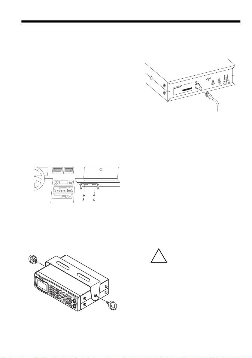
Follow these steps to mount the scan-
ner in your vehicle.
1. Choose a mounting location, then
Be sure to avoid obstruc-
use the supplied mounting bracket
as a template to mark the positions for the mounting screw
holes.
6. Connect the antenna’s cable to
ANT
the
scanner.
jack on the back of the
2. In the marked positions, drill holes
slightly smaller than the supplied
screws.
3. Attach the mounting bracket to the
mounting location using the supplied screws and lock washers.
4. Attach a rubber washer to both of
the mounting bracket’s holes.
5. Attach the scanner to the mounting bracket using the supplied
mounting knobs.
Note:
If the antenna cable’s connector
does not fit in the
also need a Motorola-to-BNC antenna
plug adapter (available at your local
RadioShack store).
ANT
jack, you might
POWERING THE
SCANNER
You can power your scanner using either the supplied DC power cord or
from your vehicle’s cigarette lighter
socket using an optional DC cigarette
lighter power cable.
Cautions:
You must use a power
source that supplies 12V
DC and delivers at least
500 mA. Its center tip must be set
to positive and its plug must fit the
scanner's
plied DC power cord meets these
specifications. Using a power cord
that does not meet these specifications could damage the scanner
or the adapter.
DC 13.8V
jack. The sup-
9
Page 10
• Always connect the adapter or DC
power cord to the scanner before
you connect it to the power
source. When you finish, disconnect the adapter or DC power
cord from the power source before
you disconnect it from the scanner.
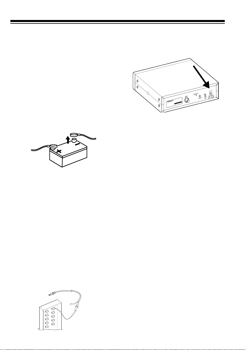
• For added safety and to protect
your scanner, disconnect the
cable from your vehicle battery’s
negative (
begin.
Follow these steps to connect the supplied DC power cord.
1. Connect the power cord’s black
wire to a chassis ground, such as
a metal screw attached to a metal
part of the vehicle’s frame. Be
sure that the screw is not insulated from the frame by a plastic
part.
2. Connect the power cord’s red wire
(with in-line fuse) to a source of
voltage that turns on and off with
the ignition switch, such as a
spare accessory terminal in your
vehicle’s fuse box.
–
) terminal before you
3. Insert the power cord’s barrel plug
into the
of the scanner.
4. Reconnect the cable to the vehicle battery’s negative (
To power the scanner from a vehicle’s
12V power source (such as a cigarette-lighter socket), you need a 12V,
500-mA DC cigarette-lighter adapter
(not supplied), available at your local
RadioShack store.
To connect an optional DC cigarettelighter power cable, insert its barrel
plug into the
of the scanner, then plug the power
cable into your vehicle’s cigarette
lighter socket.
Note:
power cable and your vehicle’s engine
is running, you might hear electrical
noise from the engine while scanning.
This is normal.
DC 13.8V
DC 13.8V
If you use a cigarette-lighter
jack on the back
–
) terminal.
jack on the back
USING THE SCANNER
AS A BASE STATION
10
You can place this scanner o n a de sk,
shelf, or table to use it as a base station.
Page 11
Using Standard AC Power
To power the scanner from an AC out let, you need an AC adapter (not supplied) with a 5.5 mm outer diameter/
2.1 mm inner diameter tip.
Cautions:
You must use a Class 2
power source that sup-
!
plies 12V DC and delivers at least 500 mA. Its center tip
must be set to positive and its
plug must fit the scanner's
13.8V
jack. Using an adapter that
does not meet these specifications could damage the scanner
or the adapter.
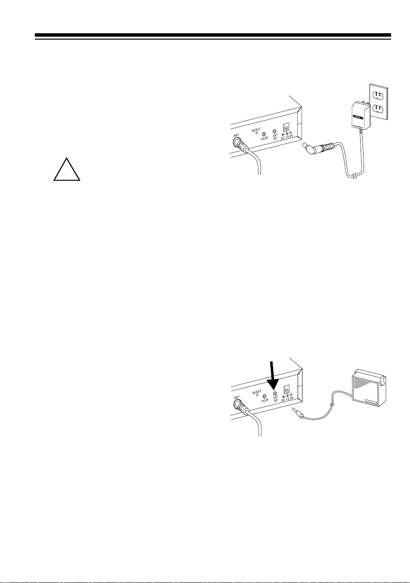
• Always connect the AC adapter to
the scanner before you connect it
to AC power . When you finish, di sconnect the adapter from AC power before you disconnect it from
the scanner.
DC
3. Plug the adapter into a standard
AC outlet.
1
2
V
CONNECTING AN
EXTENSION SPEAKER
In a noisy area, an amplified extension
speaker (available at your local RadioShack store) positioned in the right
place might provide more comfortable
listening.
1
8
Plug the speaker cable’s
mm) plug into your scanner’s
jack.
/
-inch (3.5-
EXT SP
1. Connect the adapter's 5.5 mm
outer diameter/2.1 mm inner
diameter tip to the adapter's cord
and set the barrel plug's tip to positive.
2. Insert the adapter's barrel plug
into the
DC 13.8V
jack on the back
of the scanner.
Note:
Connecting an external speaker
disconnects the scanner’s internal
speaker.
11
Page 12
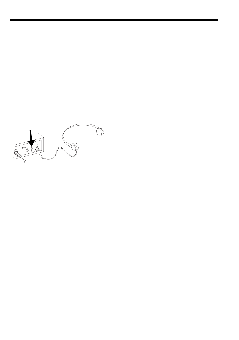
CONNECTING AN
EARPHONE/
HEADPHONES
For private listening, you can connect
an earphone or headphones with a
inch (3.5-mm) plug to the
on the back of the scanner. (Your local
RadioShack store carries a wide selection of earphones and headphones). This automatically disconnects the internal speaker.
EXT SP
Listening Safely
To protect your hearing, follow these
guidelines when you use an earphone
or headphones.
1
/
jack
• Once you set
increase it. Over time, your ears
adapt to the volume level, so a
volume level that does not cause
discomfort might still damage your
8
-
hearing.
VOLUME
, do not
CONNECTING THE CLONE
CABLE
You can transfer the programmed
data to and from another Cat. No. 20196 or Cat. No. 20-522 scanner using
the supplied clone cable. Connect the
cable between each scanner’s
jacks. See “Cloning Programmed
Data from Scanner to Scanner” on
Page 35. You can also upload or
download the programmed data to o r
from a PC using an optional PC interface kit available through your local
RadioShack store.
PC/IF
• Do not listen at extremely high
volume levels. Extended highvolume listening can lead to permanent hearing loss.
VOLUME
•Set
before you begin listening. After
you begin listening, adjust
UME
to a comfortable level.
12
to the lowest setting
VOL-
Page 13
UNDERSTANDING YOUR SCANNER
Once you understand a few simple terms used in this manual and familiarize yourself with your scanner’s features, you can pu t the scann er to work for you. You simply determine the type of communications you want to receive, then set the
scanner to scan them.
frequency
A
active frequencies, you can use the
is the tuning location of a station (expressed in kHz or MHz). To find
search
function.
You can also search the
quencies categorized by type of service.
When you find a frequency, you can store it into a programmable memory location
called a
bank
the frequencies stored there. Each time the scanner finds an active frequency, it
stays on that channel until the transmission ends.
channel
. You can then
, which is grouped with your other channels in a
service-search banks
scan
the channel-storage banks to see if there is activity on
, which are preset groups of fre-
channel-storage
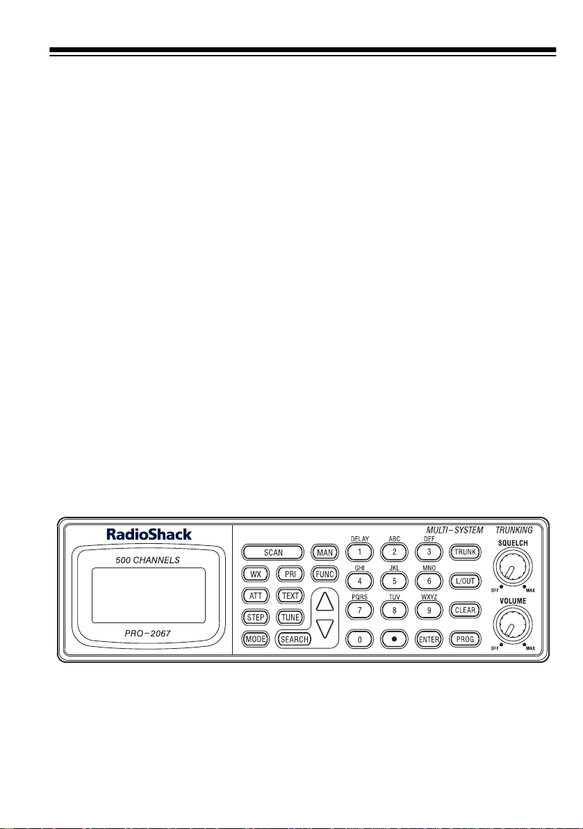
A LOOK AT THE KEYPAD
Your scanner’s keys might seem confusing at first, but this information should help
you understand each key’s function.
Note:
Some of the scanner’s keys perform more than one function and are marked
with more than one label. The steps in this Owner’s Manual show only the label on
the key appropriate to the action being performed.
SCAN
— scans through the programmed channels or ID code.
WX
— scans through the 7 preprogrammed weather channels.
(attenuate)
ATT
it off to increase it.
— turns attenuation on to reduce the sca nner ’s sen si tivit y, or t ur ns
13
Page 14

STEP
— changes the frequency step or displays the step frequency during a
search.
MODE
— changes the receive mode.
(priority)
PRI
TEXT
— lets you input text.
TUNE
— tunes a frequency along with ▲ or ▼.
— sets and turns the priority function on or off.
SEARCH
MAN
FUNC
— lets you search the ten search banks.
— stops scanning and lets you directly enter a channel number.
— lets you access various functions by pressing this key along with other
keys.
▲
or ▼ — selects the search direction during a search or while t unin g to a f requ en-
cy.
1/DELAY
— enters a 1, programs a 2-second delay for the selected channel/search
bank, or inputs characters 0 through 9.
2/ABC
— enters a 2 or inputs characters A, B, or C.
3/DEF
— enters a 3 or inputs characters D, E, or F.
4/GHI
— enters a 4 or inputs characters G, H, or I.
5/JKL
— enters a 5 or inputs characters J, K, or L.
6/MNO
— enters a 6 or inputs characters M, N, or O.
7/PQRS
— enters a 7 or inputs characters P, Q, R, or S.
8/TUV
— enters a 8 or inputs characters T, U, or V.
9/WXYZ
0
— enters a 9 or inputs characters W, X, Y, or Z.
— enters a zero or inputs characters., -, #, _, @, +, *, &, /, ', $,%,!, ^, (,), ?,
`,
,
and ^.
14
Page 15

— enters a decimal point (necessary when programming frequencies), space, or
•
hyphen (in Motorola type I code setting).
ENTER
TRUNK
L/OUT
—enters frequencies, text, and so on.
— stores the trunking ID code or holds the trunking ID while scanning.
(lockout)
— lets you lock out a selected channel, skip a specified frequency
during search, or lock out a selected ID code.
CLEAR
PROG
— clears an incorrect entry.
(program)
— programs frequencies into channels.
15
Page 16
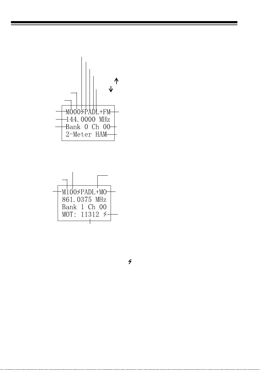
A LOOK AT THE DISPLAY
Bank 0–(9)
Manual Mode
Current Frequency
Current Bank
Bank 1
(M)anual Mode
(P)rogram
(S)can
(I)D Program
Receiving a Signal (
Priority Freq. (T)runked
Attenuate (
Delay (
Locked (
Out
Channel
00–(49)
Manual Mode (AM or FM)
Channel 00–(49)
Talk Group ID
Manual Mode
Out
no signal)
•
no attenuation)
•
no delay)
•
Scanning Up)
(
Scanning Down)
Current
Mode is FM
Channel
Stored Text
(+) Open
(–) Closed
Motorola
Detecting a
Trunking or
Tone Signal
Code
If you enter the ID text
tag in an ID code, the
scanner displays it
instead of the ID code
.
and
16
Page 17
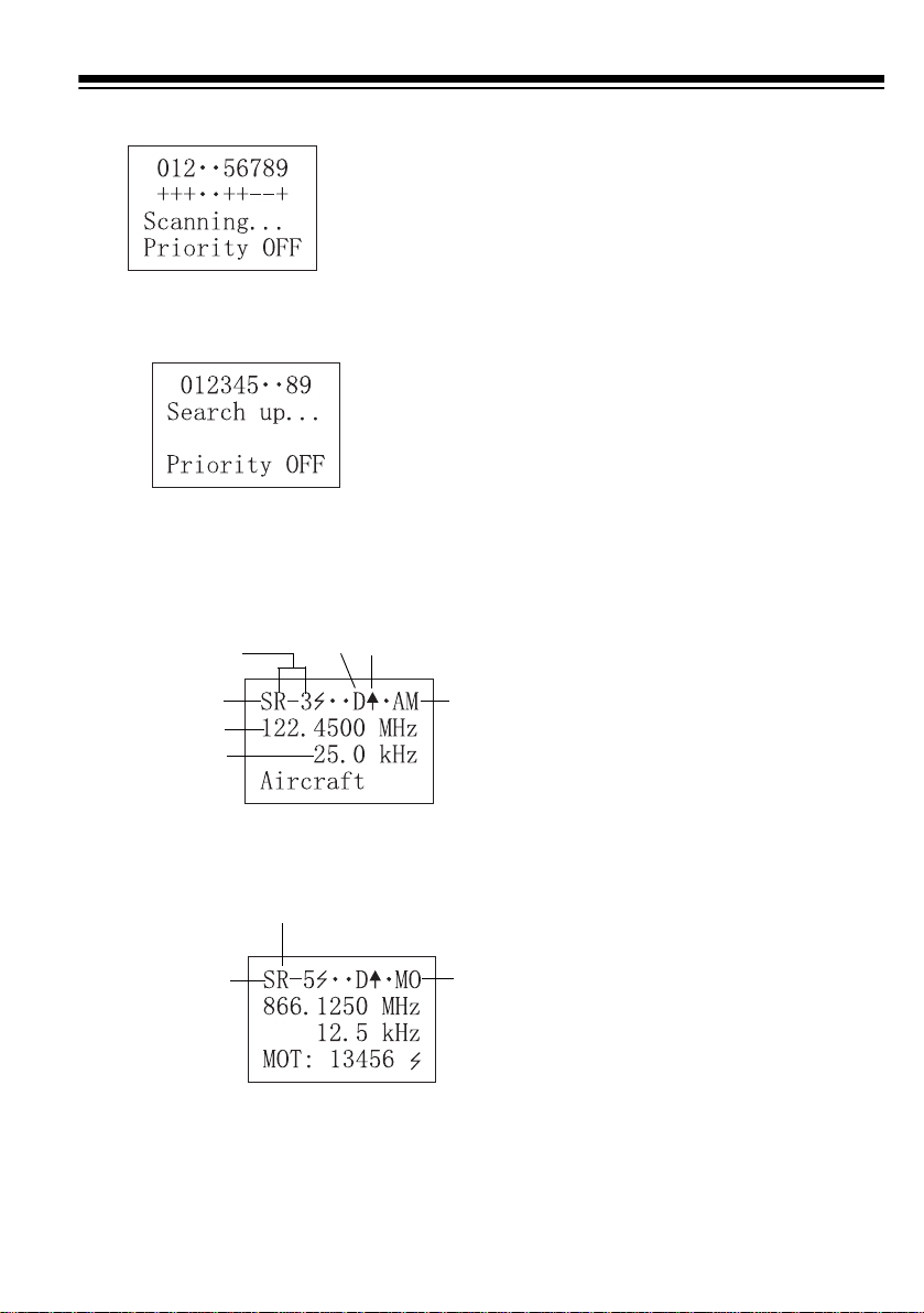
Scan Mode
Search Mode
Bank Off
•
Selected for Scanning
+
in Open Mode
Selected for Scanning
–
in Closed Mode
6 and 7 are turned off
Searching
Frequency
for Range
in Bank 3
Search Mode
Received
Frequency
Stepping
Search Mode
Delay Scanning Up
AM
Search Mode
Search Bank 5
Motorola
Search Mode
17
Page 18

UNDERSTANDING
BANKS
UNDERSTANDING
CTCSS/DCS
Channel Storage Banks
To make it easier to identify and select
the channels you want to listen to,
channels are divided into 10 banks
(0–9) of 50 channels (00 to 49) each.
Use each channel-storage bank to
group frequencies, such as those
used by the police department, fire department, ambulance services, or aircraft (see “Guide to the Action Bands”
on Page 45). For example, the police
department might use four frequencies, one for each side of town. You
could program the police frequencies
starting with 000 (the 1st channel in
bank 0) and program the fire department frequencies starting with 100
(the 1st channel in bank 1). The first
digit identifies the bank (0–9). The
second and third digits identify the
channel within the bank (00–49).
Continuous Tone Coded Squelch System (CTCSS) and Digital Coded
Squelch (DCS) are two methods used
to prevent interference by other radio
communications. Your scanner can
receive transmissions that use these
codes.
When your scanner receives a CTCSS transmission,
pears. When your scanner receives a
DCS transmission,
line) and a 3-digit code appear.
PL
(private line) ap-
DPL
(digital private
PL Codes
PL codes are low-frequency audio
tones that are used to differentiate different users on the same channel. PL
codes appear according to the EIA
standard CTCSS tones, and range
from 67.0 Hz to 254.1 Hz. PL codes
are displayed directly as a frequency.
Search Banks
This scanner is able to search 10
search banks. You can also replac e a
bank with one of the preprogrammed
service bands. (For the default setting,
see “Searching a Preprogrammed
Frequency Range” on Page 25).
18
DPL Codes
DPL codes are similar to PL codes,
except they might be transmitted as
either tones or digital codes. Although
there are as many as 4096 DPL
codes, only about 100 are actually
used.
DPL codes appear in the format
Dxxx
, where
xxx
is an octal code.
Page 19

UNDERSTANDING YOUR
SCANNER’S MODES
Open and Closed Modes
You can set your scanner to change
the way it receives signals. These settings, called
mode
, affect how the scanner receives signals from communications
systems that use some type of closed
squelch (such as PL, DPL, LTR, MOT,
and ED systems). You can set each of
the scanner’s channel storage banks
to open or closed mode.
open mode
and
closed
When you set a channel storage bank
to open mode,
der the bank’s number while scanning.
When you set a channel storage bank
to closed mode,
der the channel storage bank's number while scanning. Or,
CLOSED
in manual mode or while the scanner
is receiving a signal during scanning.
See “Changing the Open/Closed
Mode” on Page 32 for more information about setting the open and closed
modes.
appears while the scanner is
+
(open) appears un-
–
(closed) appear un-
OPEN
or
In open mode, the scanner scans signals transmitted in all systems. In
closed mode, the scanner scans signals transmitted only under the following conditions:
• When the signals are in the FM
mode.
• When the signals are in the LT,
MO, or ED mode
ID code matches the programmed
ID code.
• When the signals are in the PL or
DPL mode
code matches the progra m m ed I D
code.
Note:
When the signals are in the
PL or DPL mode, the scanner
receives all signals on a channel
when the ID code is set to NONE.
You can also select the users or talk
groups you want the scanner to receive in closed mode.
and
the signal's
and
the signal's ID
LTR (E. F. Johnson) Mode
You can set your scanner so it decodes the talk group IDs used with
LTR systems. This setting is called the
LTR mode
LTR systems are trunking systems
used primarily by business or private
communications service providers,
such as taxicabs, delivery trucks, and
repair services. These systems encode all trunking information as digital
subaudible data that accompanies
each transmission. Users on an LTR
system are assigned to specific talk
groups, which are identified by the radio as six-digit numbers. These numbers are in the form
A
= Area code (0 or 1)
H
= Home repeater (01 through 20)
U
= User ID (000 through 254)
.
AHHUUU
, where:
19
Page 20

When the scanner receives a transmission on a channel set to the LTR
mode, it first decodes the LTR data included with the transmission. In the
open mode, the scanner stops on the
transmission and displays the talk
group ID on the bottom line of the display. In the closed mode, the scanner
only stops on the transmission if the
LTR data matches a talk group ID that
you have stored in the bank’s talk
group ID list and have not locked out.
LTR systems are frequently programmed so that each radio has a
unique ID code.
Motorola Mode
When the scanner receives a transmission on a channel set to the Motorola mode, it first decodes the talk
group ID data included with the transmission. In the open mode, the scanner stops on the transmission and
displays the talk group ID on the bottom line of the display. In the closed
mode, the scanner only stops on the
transmission if the talk group ID
matches a talk group ID that you have
stored in the bank’s talk group ID list
and have not locked out.
Motorola trunking systems come in
three categories:
Type I/II Hybrid
plays and uses talk group IDs in slightly different ways.
Type I, Type II
. Each category dis-
, and
You can set your scanner so it decodes the talk group IDs used with
Motorola trunking systems. This setting is called the
Motorola systems are trunking systems used primarily by business and
public safety groups to efficiently allocate a small number of frequencies
(as few as 5) to many groups of users
(as many as several thousand). To do
this, each group of users in the system
is assigned to a specific talk group.
For example, the east side patrol officers might all be assigned to talk group
2160. One channel in the system is
continuously transmitting data that
identifies which talk groups are active
on which channel. In addition, this talk
group information is also transmitted
as subaudible data on each active
channel.
20
Motorola mode
.
Motorola Type I IDs are in the form
FFF-SS
FFF
SS
Type I systems are usually organized
with different user groups assigned to
different fleets. For example, a valid
fleet/subfleet ID identifying all detectives within a police department might
be
police users and
tective division.
To properly map the raw Type I d at a
to the correct fleet-subfleet format,
you must program the correct fleet
map into the scanner. Fleet map information is widely available on the Internet for most Type I systems in use.
, where:
= Fleet ID
= Subfleet ID
000-12
, where
000
identifies all
12
identifies the De-
Page 21

Type II system talk groups are identified by a 5-digit number. Valid talk
group IDs are divisible by 16. If you try
to enter an invalid talk group ID, the
scanner rounds the ID down to the
next valid ID.
Type I/II hybrid systems use both
fleet-subfleet and 5-digit formats for
talk group IDs.
EDACS frequencies are organized in
a specific order. Each frequency is assigned a Logical Channel Number
(LCN). For the scanner to correctly
switch to an active frequency, you
must program the frequencies in LCN
order, starting with Memory 01.
EDACS talk group IDs are entered as
a 4-digit decimal number from 0000 to
4096.
Note:
If the scanner decodes control
channel data while receiving transmissions from a Motorola trunking sys-
CNTRL
tem,
line of the display. For example:
appears on the bottom
EDACS Mode
You can set your scanner so it decodes the talk group IDs used with
EDACS (GE/Ericsson) trunking systems. This setting is called the
EDACS mode
EDACS systems are trunking systems
used primarily by business or private
communications service providers, as
well as by some public safety organizations. EDACS systems transmit active talk group information only on a
dedicated control channel.
.
When there is activity on an EDACS
system, that information is sent out on
the control channel. The scanner decodes the ID for the active talk group.
In the open mode, the scanner then
goes to the transmission and displays
the talk group ID on the bottom line of
the display. In the closed mode, the
scanner only goes to transmissions
that have IDs that match a talk group
ID that you have stored in the bank’s
talk group ID list and have not locked
out.
Because EDACS scanning requires
clear reception of the control channel
at all times, EDACS systems tend to
have a smaller usable area. An external antenna can greatly improve
EDACS scanning in a fringe area. If
you are having trouble scanning an
EDACS system, try manually selecting the data channel. If you are gett ing
good reception, the scanner will indicate talk group
ing your location or using an outdoor
antenna to improve reception.
CTL-01
. Try chang-
21
Page 22

OPERATION
TURNING ON THE
SCANNER AND SETTING
SQUELCH
1. Turn
2. To turn on the scanner, turn
3. Turn
4. To turn off the scann er, tu rn
22
SQUELCH
wise until the indicator points to
MIN
.
UME
clockwise.
Multi-System
appears. Then, after about 3 seconds, you hear a hissing sound.
SQUELCH
leave it set to a point just after the
hissing sound stops.
UME
counterclockwise to
Notes:
• The scanner does not scan if
there are no frequencies stored
in channels. If the scanner does
not scan and you have already
stored frequencies in channels,
SQUELCH
turn
wise.
• If the scanner picks up
unwanted, partial, or very weak
transmissions, turn
clockwise to decrease the scanner’s sensitivity to these signals. If you want to listen to a
weak or distant station, turn
SQUELCH
SQUELCH
• If
always hear a hissing sound,
the scanner will not scan properly.
fully counterclock-
Welcome to
Trunking
clockwise and
OFF
.
further clock-
SQUELCH
counterclockwise.
is adjusted so you
VOL-
VOL-
• To ensure the scanner operates
properly while in the trunking
mode, we suggest you set
SQUELCH
steps, even if the scanner is
automatically muted.
using the above
STORING KNOWN
FREQUENCIES INTO
CHANNELS
Good references for active frequencies are the RadioShack
Guide including Fire and Emergency
Services
quency Directory
quency Directory
directories every year, so be sure to
get a current copy. You can also
quickly and easily program your scanner by using
software, available at your local
RadioShack store.
Follow these steps to store frequencies into channels.
1. Press
ber (0–9) and the channel number
(00–49) where you want to store a
frequency, then press
M
appear.
2. Press
3. Use the number keys and
enter the frequency (including the
decimal point) you want to store.
If you make a mistake, hold down
CLEAR
delete a single digit or about 2
seconds to delete all digits.
Official Aeronautical Fre-
,
, and
. We update these
Scanner Data Manager
MAN
, enter the bank num-
and the channel number
PROG
. M changes to P.
for about a second to
Police Call
Maritime Fre-
MAN
again.
to
•
Page 23

4. Press
ENTER
to store the fre-
quency into the channel.
Notes:
• If you made a mistake in Step
Invalid Freq
3,
appears
and the scanner beeps when
you press
ENTER
. Simply start
again from Step 3.
• Your scanner automatically
rounds the entered frequency
down to the nearest valid frequency. For example, if you
enter a frequency of 151.473,
your scanner accepts it as
151.470.
• The scanner automatically
pauses 2 seconds on a channel
after a transmission ends
before it proceeds to the next
channel. To turn off delay, press
FUNC
then
DELAY
. (See “Using
Delay” on Page 30).
5. If necessary, change the receive
mode (see “Changing the Receive
Mode” on Page 33). If you select
PL or DPL mode, enter the PL o r
DPL code by pressing
STEP
(to
move through the codes upward)
or
FUNC
then
STEP
(to move
through the codes downward).
6. To program the next channel in
sequence, press
PROG
and
repeat Steps 3 through 5.
for easy identification of channel
transmissions, trunk IDs, or banks.
Assigning a Text Tag to a
Channel
1. Press
2. Press
3. Press
4. Enter the desired text using the
5. Press
MAN
, enter the bank number or channel number where you
want to enter the text, then press
MAN
again. M and the channel
number appear at the upper left
corner of the display (for example:
M100).
PROG
. M changes to P on
the display.
TEXT
. The cursor appears
at the third line on the display.
number keys (see “Text Input
Chart” on Page 24).
Note:
If you make a mistake,
press ▼ or ▲ to move to the character you want to change.
ENTER
to input the text.
Assigning a Text Tag to a
Bank
1. Select a channel within the
desired bank by pressing
and entering the 3-digit bank n umber (000 for bank 0 or 200 for
bank 2, for example). Press
again, then press
PROG
MAN
MAN
.
STORING TEXT T AGS
You can customize your scanner by
storing text tags (up to 12 characters)
2. Press
FUNC
then 6. The cursor
appears at the 3rd line on the display.
23
Page 24

3. Enter the desired text using the
keypad then press
Note:
If the channel is programmed
ENTER
.
for PL, DL, LT, MO or ED mode, the
scanner displays the ID number from
the bank name.
To access the numbers, after you
FUNC
press
and 6, press 1 then the
desired number.
To enter a lowercase character or a
character from the second set for key
0
, press 0 then
FUNC
.
Text Input Chart
Press
1
2
3
4
5
6
7
8
9
0
To Enter a Character from this
1, 2, 3, 4, 5, 6, 7,
0
8
, 9,
A, B, C, a, b, c
D, E, F, d, e, f
G, H, I, g, h, i
J, K, L, j, k, l
M, N, O, m, n, o
P, Q, R, S, p, q, r, s
T, U, V, t, u, v
W, X, Y, Z, w, x, y, z
., -, #, _, @, +, *,
&
, /, ', $,%,!, ^,
,?,
(,)
Group
, `,
^
For example, input “HAM 6m” as follows:
1. “H” is the second letter associated
with 4 on the keypad. Press
2
press
.
4
then
2. “A” is the first letter associated
with 2 on the keypad. Press
1
press
.
2
then
3. “M” is the first letter associated
with 6 on the keypad. Press
1
press
4. “space” Press
.
.
•
6
then
5. “6” is the sixth number associat ed
with 1 on the keypad. Press
6
6.
press
m
.
is the first letter associated with
6 on the keypad. Press
FUNC
(for the lowercase set) then
1
.
1
then
6
and
24
•
CL
Space
Back Space
Page 25

FINDING AND STORING
ACTIVE FREQUENCIES
Search
Bank
Search
Range (MHz)
Description
You can search for transmissions
within ten ranges of frequencies,
called a search bank. The search
bank is divided into ten search bands.
You can change the bands with the
preprogrammed search bands in the
scanner. You can also change the
search bank’s search ranges manually.
Notes:
• You can use the scanner’s delay
feature while searching the service bank. See “Using Delay” on
Page 30.
• The scanner does not search
locked-out frequencies while
searching ranges.
Searching a Preprogrammed
Frequency Range
The scanner contains these preprogrammed search ranges, stored in
search banks (0–9).
3 118.000–
136.00
4 156.250–
157.425
5 866.000–
868.9875
6 50.000–
54.000
7 144.000–
148.000
8 440.000–
450.000
9 462.550–
462.725
Aircraft
Marine
800 MHz
6 Meter
Ham
2 Meter
Ham
70 cm Ham
User Bank
Follow these steps to select preprogrammed search ranges and search
them for active frequencies.
1. Press
SEARCH
. The scanner
searches the active search bank.
Current
Search
Bank
Search
Bank
0 460–460.625 Police
1 153.725–
2 462.925–
Search
Range (MHz)
156.000
463.175
Description
Police/Fire
Medical
Note:
To reverse the search
▲
direction, press
or ▼.
2. Using the number keys, enter the
search bank number for each
search range you want to select or
remove.
25
Page 26

3. When the scanner finds an active
frequency, it stops searching. To
save the frequency into a channel
in the channel storage bank (bank
9 only), press
Stored @ 9xx
FUNC
appears on the
bottom row of the display (
then
ENTER
xx
the channel number). Press ▲ or
▼
to continue searching for addi-
tional active frequencies.
Notes:
• During a search, you can manually change the band mode or frequency step. See “Changing the
Receive Mode” on Page 33 or
“Changing the Frequency Step”
on Page 33.
• If channel storage bank 9 does
not contain any empty channels,
Bank 9 full.
appears on the
display’s lower line.
• To pause the search, press
TUNE
then
again, press
. To begin searching
SEARCH
.
FUNC
Storing a Frequency to a
Specified Channel
is
7. If desired, press
SEARCH
to return
to the search mode.
.
Changing a Search Range
with a Preprogrammed Range
You can replace the search range with
one of the preprogrammed ranges.
1. Press
FUNC
then
enter search program mode.
and the search bank number of
the current range appear at the
display’s upper left corner.
2. Press ▲ or ▼ to select the search
bank you want to replace.
3. Press
FUNC
then 5.
search bank number appear at
the display’s upper left corner.
SEARCH
?SR
and the
to
PSR
1. When the scanner stops on the
desired frequency, press
2. Press
3. Press
TUNE
MAN
.
.
FUNC
4. Select the desired channel using
a number key then press
MAN
again.
5. Press
6. Press
PROG
FUNC
.
then
TUNE
to store
the frequency.
26
.
Note:
If you do not press
5
within
about 3 seconds after you
pressed
FUNC
, the scanner stops
search program mode. Start over
at Step 1.
Page 27

4. Press ▲ or ▼ to select the preprogrammed search range.
scanner does not accept the
entry.
5. Press
search range.
ENTER
to replace the
Manually Changing a Search
Range
1. Press
enter search program mode.
and a search bank number
appear at the display’s upper left
corner.
2. Press ▲ or ▼ to select the desired
search bank number.
3. Use the number keys to enter the
lowest frequency range you want
to search, then press
store the frequency.
4. Use the number keys to enter the
highest frequency range you want
to search, then press
again to store the frequency.
Notes:
• If you enter a higher frequency,
FUNC
then
then enter a lower frequency,
the scanner automatically
exchanges the frequencies on
the display. It displays the lowest frequency first and the highest frequency second.
SEARCH
ENTER
ENTER
to
PSR
to
5. To assign a name to the search
ENTER
TEXT
twice, then
.
▲
range, press
enter the name. If you want to edit
existing text, repeatedly press
or ▼ to move the cursor across
the text. Enter the appropriate text
and press
SCANNING THE
CHANNELS
To begin scanning channels or to start
scanning again after monitoring a specific channel, press
Note:
You must store frequencies into
channels before the scanner ca n scan
them. The scanner does not scan
empty channels.
The scanner scans through all channels (except those you have locked
out) in the active banks (see “Turning
Channel-Storage Banks Off and On”
and “Locking Out Channels, Frequencies, and Trunking IDs” on Page 30).
Turning Channel-Storage
Banks Off and On
SCAN
.
• You cannot search more than
one frequency band at a time.
When manually setting search
ranges, if you enter frequencies
that are in different bands, the
To turn off banks while scanning,
press the bank’s corresponding number key until the bank’s number disappears. The scanner does not scan any
27
Page 28

of the channels within the banks you
have turned off.
Notes:
• You cannot turn off all banks.
There must be at least one active
bank.
Notes:
• You cannot change the step frequency while tuning.
• You can change the receiving
mode while tuning.
• You can manually select any
channel in a bank, even if the
bank is turned off.
To turn on banks while scanning,
press the bank’s correspondin g number key until the bank’s number appears.
MANUALLY TUNING A
FREQUENCY
1. Press
2. Use the number keys to enter the
3. Press
4. Press ▲ to move up one tuning
TUNE
.
frequency.
ENTER
.
step. Press ▼ to move down one
tuning step. To move up or down
in 1 MHz increments, press
then ▲ or ▼.
FUNC
DELETING
FREQUENCIES FROM
CHANNELS
1. Press
2. Use the number keys to enter the
3. Press
4. Press
5. Press
6. Press
MAN
.
channel containing the frequency
you want to delete.
MAN
again.
PROG
to enter the program
mode.
play.
number changes and the display
shows
M
changes to P on the dis-
FUNC
.
CLEAR
0.0000 MHz
. The frequency
.
LISTENING TO THE
WEATHER BAND
To save the frequency into a
channel (bank 9 only), press
FUNC
9xx
appears (xx channel num-
ber).
When the scanner stops on a frequency while searching, press
TUNE
.
28
then
ENTER
Stored @
.
FUNC
then
The FCC (Federal Communications
Commission) has allocated channels
for use by the National Oceanic and
Atmospheric Administration (NOAA).
Regulatory agencies in other countries have also allocated channels for
use by their weather reporting authorities.
Page 29

NOAA and your local weather reporting authority broadcast your local forecast and regional weather information
on one or more of these channels.
Listening to a Weather
Channel
To hear your local forecast and regional weather information, press
Your scanner scans through the
weather band then stops within a fe w
seconds on the strongest weather
broadcast.
WX
Displaying Weather
Messages
The weather service precedes each
weather alert with a digitally-encoded
SAME signal, then a 1050 Hz tone.
You can set the scanner so, if you are
monitoring a weather channel with a
digitally-encoded SAME signal when
an alert is broadcast, the scan ner will
decode and display the SAME message, showing the type of alert being
broadcast (or
it does not recognize the event code).
Unknown Message
if
Notes:
.
• The scanner does not display the
actual location referenced by
SAME messages. It uses only the
message portion of the SAME signal.
• Your scanner can also receive
weather alert tones (see “Priority”
on Page 31).
To set the scanner to decode and display SAME messages, press
then WX while you listen to the weather channel.
Cancel: F + WX
To set the scanner out of the
standby mode, press
again.
DIG WX STBY
DIG WX STBY
appear.
FUNC
disappears.
FUNC
SAME
then
and
WX
29
Page 30

SPECIAL FEATURES
USING DELAY
Many agencies use a two-way radio
system that might have a period of 2
or more seconds between a transmission and a reply. To keep from missing a reply, the scanner automatically
pauses 2 seconds on a channel after
a transmission ends before it proceeds to the next channel.
To turn delay on or off, press
DELAY
then
.
FUNC
LOCKING OUT
CHANNELS,
FREQUENCIES, AND
TRUNKING IDS
You can scan existing channels or
search frequencies faster by locking
out channels or frequencies that have
a continuous transmission, such as a
weather channel.
mode, the lockout is removed
when power is disconnected then
reapplied to the scanner. This
makes it easy to temporarily lock
out trunking data channels.
To remove the lockout from a channel,
manually select the channel and press
L/OUT
until L disappears.
Reviewing the Locked-Out
Channels
To review all channels that are locked
out, first press
L/OUT
then
channel. When you finish reviewing
locked-out channels, press
MAN
then press
to view each locked-out
MAN
FUNC
.
Locking Out Frequencies
To lock out a frequency during a
search, press
ner stops on the frequency. The scanner locks out the frequency then
continues searching.
L/OUT
when the scan-
Locking Out Channels
To lock out a channel while scanning,
L/OUT
press
on the channel. Or select the channel
then hold down
Notes:
• You can still manually select
locked-out channels.
• If you lock out a channel that is set
to a Motorola trunking mode while
using the subaudible decoding
30
when the scanner stops
L/OUT
until L appears.
Notes:
• You can lock out as many as 50
frequencies in each bank. If you
try to lock out more,
full!
• If you lock out all frequencies in
one search bank and only that
search bank is activated,
up...
out!
does not search. Select a different
bank or unlock some frequencies.
appears.
All ranges locked
appears and the scanner
Memory
Search
Page 31

Reviewing Locked-Out
Frequencies
frequencies are cleared within a bank,
L/O list is empty
appears.
Follow these steps to review the frequencies within a search bank that
you locked out.
1. Press
2. Press
3. Press
4. Repeatedly press ▲. The scanner
SEARCH
FUNC
locked-out frequency in the
selected search bank appears. If
the search bank has no lockedout frequency,
empty.
FUNC
search bank and begin the search
for locked-out channels within that
bank.
displays all locked-out frequencies
within the bank.
to start searching.
L/OUT
then
. The first
L/O list is
appears.
then ▲ to select a
Clearing a Locked-Out
Frequency
To clear a locked-out frequency, select that frequency then press
CLEAR
Clearing All Locked-Out
Frequencies in a Search Bank
1. Press
2. Repeatedly press ▲ or ▼ to select
3. Press
4. Press
FUNC
a search bank.
FUNC
list
other
quencies, or press any other key
to cancel clearing.
clear? 1=YES Press
key for NO.
1
to clear all locked-out fre-
cleared
seconds if you press
5. Press
searching.
SEARCH
SEARCH
then
then 4.
.
Confirm
appears.
List
appears for about 2
1
.
to continue
PRIORITY
The priority feature lets you scan
through channels and still not miss important or interesting calls on a channel you select. When a channel is
selected as the priority channel and
priority is turned on, the scanner
checks that channel every 2 s econds.
If there is activity on the channel, the
scanner stays on the channel until the
.
activity stops.
The frequency is unlocked and
locked
onds. Then the next locked-out
frequency appears. If all locked out
appears for about 2 sec-
Un-
The scanner is preset to select Channel 00 in Bank 8 as the priority channel. You can program a different
channel (including a weather channel)
as the priority channel.
31
Page 32

Notes:
Follow these steps to program a channel as the priority channel.
Follow these steps to program a
weather channel as the priority channel.
• The scanner does not stay on the
priority channel while the scanner
is receiving trunking frequencies.
• If you program a weather channel
as the priority channel, the scanner stays on that channel only
when it detects the weather alert
tone.
• The scanner cannot set a channel
as the priority channel if the channel’s receive mode is
ED
or
.
1. Press
2. Use the number keys to enter the
3. Press
MAN
.
channel number you want to program as the priority channel, then
MAN
press
appears to the right of the frequency.
.
FUNC
then
LTR, MOT
PRI
Pri
.
To turn on the priority feature, press
PRI
while scanning.
Priority WX
(or
ity to a weather channel) appears for
about 3 seconds then
scanner checks the priority channel
every 2 seconds and stays on the
channel if there is activity (or if it detects a weather alert tone if a weather
channel is the priority channel), and
Pri
appears and S or M changes to
P
.
,
To turn off the priority feature, press
PRI
Priority OFF
.
disappears.
Notes:
• If you program a weather frequency into the priority channel
and the scanner detects a
weather alert tone on that frequency, the scanner sounds the
alert tone.
• The scanner always monitors t he
priority channel even if the bank it
is contained in is set to closed
mode (see “Changing the Open/
Closed Mode”).
Priority ON
if you set the prior-
P
appears. The
appears and
P
1. Press
2. Select the weather channel you
3. Press
32
WX
.
want to program as the priority
channel.
FUNC
then
appears to the right of the frequency.
PRI
.
Pri
CHANGING THE OPEN/
CLOSED MODE
You can set each of the scanner’s
banks to open mode or closed mode.
When a bank is set to open mode, the
scanner receives all transmissions on
the frequencies in that bank. When a
bank is set to closed mode, the scan-
Page 33

ner receives transmissions only when
a preset ID code is also transmitted,
and the ID code appears. In closed
mode, the scanner does not receive
transmissions if they do not have an
ID code or if the ID code does not
match the preset ID code.
Note:
You can set AM and FM frequencies within banks to open or
closed mode.
Follow these steps to select a bank
and change it to open or closed mode.
If you want to listen to private line or
trunking transmissions in closed
mode, you might have to change th e
receive mode.
To change the receive mode, repeatedly press
changes as follows:
Display Description
AM
FM
MODE
. The receive mode
AM Mode
FM Mode
1. Press
2. Press
3. Press
MAN
.
FUNC
then repeatedly press
▲
or ▼ to select the bank you
want to change.
FUNC
then 2.
Bank CLOSED
or
the tenth digit from the left at the
top line of the display changes
+
from
to – or vice versa.
Bank OPEN
appears. Then
CHANGING THE
RECEIVE MODE
The scanner is preset to the most
common AM or FM receive mode for
each frequency range.
The preset mode is correct in most
cases. However, some amateur radio
transmitters and trunked systems do
not operate in the preset mode. If you
try to listen to a transmission when the
scanner is not set to the correct receive mode, the transmission might
sound weak or distorted.
PL
DL
LT
MO
ED
FM Mode, Private Line (with
67.0–254.1 Hz PL code)
FM Mode, Digital Private
Line (with 3-digit DPL code)
FM Mode, LTR Trunking
System (with 6-digit ID
code)
FM Mode, Motorola Trunking System (with a 4- or 5digit ID code)
FM Mode, EDACS Trunking
System (with 4-digit ID
code)
CHANGING THE
FREQUENCY STEP
The scanner searches at a preset frequency step for each frequency range.
These are the frequency steps your
scanner uses for each frequency
range.
33
Page 34

Range (MHz)
Search Step
(kHz)
USING THE
ATTENUATOR
29.000-54.000 5, 10, 15, 20,
25, 30, 50, 100
108.000-136.9875 12.5, 25, 50,
100
137.000-174.000 5, 10, 15, 20,
25, 30, 50, 100
380.000-512.000 12.5, 25, 50,
100
806.000-823.9875 12.5, 25, 50,
100
849.000-868.9875 12.5, 25, 50,
100
894.000-960.000 12.5, 25, 50,
100
To change the frequency step while
moving between frequencies within a
search band, repeatedly press
Or,
follow these steps to change the
STEP
frequency step within a specific bank.
1. Press
SEARCH
.
To reduce interference or noise
caused by strong signals, you can reduce the scanner’s sensitivity to these
signals (called
attenuation
). You can
set attenuation for each of the scanner’s channels.
Note:
If you turn on this feature, the
scanner might not receive weak signals.
To reduce the scanner’s sensitivity on
the current channel, repeatedly press
ATT
until A appears. To turn off attenu-
ation, press
ATT
again. A disappears.
T URNING THE KEY T ONE
ON AND OFF
.
Each time you press any of the scanner’s keys, the scanner sounds a
tone. Follow these steps to turn the
scanner’s key tone off or on.
2. Select a bank.
3. Turn
SQUELCH
fully counterclock-
wise until the indicator points to
MIN
.
4. Repeatedly press
STEP
until you
reach the desired step.
5. Turn
SQUELCH
clockwise and
leave it set to a point just after the
hissing sound stops.
34
1. If the scanner is on, tu rn
VOLUME
counterclockwise until it clicks to
turn the scanner off.
2. Turn
VOLUME
clockwise to turn
the scanner on.
Multi-System
Welcome To
Trunking
appears.
3. While
System Trunking
press
2
Welcome To Multi-
1
to turn on the key tone or
to turn it off.
appears,
Page 35

CHANGING THE
DISPLAY CONTRAST
1. Press
2. Press
3. Press ▲ or ▼ to select the desired
4. Press
MAN
FUNC
Down
trast.
contrast.
ENTER
.
then 9.
Use Up/
keys to set con-
appears on the display.
to store the setting.
CLONING
PROGRAMMED DATA
FROM SCANNER TO
SCANNER
You can transfer the programmed
data to and from another RadioShack
Cat. No. 20-196 or Cat. No. 20-522
scanner using the supplied clone cable. To clone the data, follow these
steps.
1. Turn on both scanners.
2. Connect the supplied clone cable
to each scanner’s
CLONE MODE UP to send,
remove
appears.
3. Press
data?
key for
cable to exit
Confirm send
▲
.
1=Yes Press other
No.
appears.
PC/IF
jack.
4. Press
other unit or press any other key
to cancel the operation.
The scanner sends the data. To exit
the clone mode, remove the cable.
1
to send the data to the
35
Page 36

TRUNKING OPERATION
The scanner tracks transmissions that
use the Motorola
(such as Smartnet and Privacy Plus)
and hybrid analog trunking systems,
plus GE/Ericsson (EDACS) and EF
Johnson (LTR) type systems, which
are extensively used in many communication systems.
Trunking systems allocate a few frequencies to many different users.
When the mobile unit transmits a signal, one frequency is chosen from
among the allocated frequencies in
that trunking system. The user’s
talk group
To receive trunking signals, you must
store all the trunking group frequencies in one bank (see “Storing Known
Frequencies into Channels” on
Page 22) and input ID codes in the ID
memory (see “Finding and Storing Active Frequencies” on Page 25). To listen to the transmission, the mode of
the programmed channel mu st be the
same as that of the trunking channel
(LT, MO, or ED).
When an ID code is received, the ID
list for the bank is searched, and if
found, the text name stored for the ID
appears. If not found, scanning resumes immediately unless the bank is
in open trunking mode.
Note:
There might be more than one
talk group transmitting at a time in
some Motorola trunking systems. If
you set the scanner to manually tune
in Motorola trunking mode, you will
hear the talk group on that channel,
but the display will alternate between
all active IDs.
®
Type I and Type II
is sent with the signal.
ID
Trunking group frequencies are included in the supplied
Trunking Guide
and talk group information is also
widely available on the Internet, at
. Frequency fleet map
www.trunkscanner.com
Police Call
for example.
UNDERSTANDING
TRUNKING
In the past, groups that transmit frequently, such as police departments,
could transmit on only a few frequencies. This resulted in heavy traffic and
often required 2-way radio users to
wait for a specific frequency to clear
before transmitting. Trunked systems
allow more groups of 2-way radio users to use fewer frequencies. Instead
of selecting a specific frequency to
transmit on, a trunked system chooses one of several frequencies when
the 2-way radio user transmits. The
system automatically transmits the
call on that frequency, and also sends
a code that identifies that 2-way radio
user’s transmission on a control channel.
This scanner lets you easily hear both
the call and response transmissions
for that 2-way radio user and therefore
follow the conversation. For EDACS
and Motorola (above 806 MHz range),
the scanner monitors the control channel between each transmission to identify talk groups. For some Motorola
(under 512 MHz range) and LTR systems, the scanner uses the subaudible
data sent with each transmission to
identify talk groups.
36
Page 37

SETTING SQUELCH FOR
THE TRUNKING MODE
Your scanner automatically mutes the
audio during trunk scanning when it
decodes control channel data. However, we recommend you turn
clockwise and leave it set to a point
just after the hissing sound stops. This
lets the scanner quickly acquire the
data channel.
SQUELCH
• If you are programming trunked
frequencies for Motorola Type I
and hybrid systems, you must first
program the fleet map (see “Programming Fleet Maps” on
Page 39).
• You must store frequencies using
the subaudible trunking method in
banks mode by mode.
Follow these steps to program trunked
frequencies.
PROGRAMMING
TRUNKING
FREQUENCIES
You program trunking frequencies just
like non-trunked frequencies, except
that you must store the appropriate
mode (MO, ED, or LT) with each frequency.
Notes:
• You can store only one trunked
EDACs and Motorola channel in a
bank. You can, however, mix LTR
and conventional channels in a
bank.
• If you are scanning UHF trunking
frequencies under the 512 MHz
range using subaudible data and
are not using a base frequency
and offset, lock out all data channels. See “Programming Motorola
Trunking Systems (UHF-Lo)” on
Page 38 and “Locking Out Channels, Frequencies, and Trunking
IDs” on Page 30. Turn off the
scanner to remove the lockouts.
1. Press
2. Repeatedly press
3. Press
4. Store the trunking frequencies into
PROG
and select the bank,
then press
program mode.
LT
for EF Johnson, MO for Motorola, or
Ericsson) system to scan. This
sets the talk group ID decoding
method to be used for the bank.
Notes:
• If you select
MO
not scan trunked frequencies.
Instead, you see:
• If you programmed a Motorola
Type I or Hybrid system, see
“Programming Fleet Maps” on
Page 39.
mode.
subsequent channels in the same
TRUNK
ED
for the EDACS (GE/
, or ED, the scanner does
PROG
to enter the ID
MODE
to select
--
instead of LT,
to enter the program
37
Page 38

bank (see “Storing a Frequency to
a Specified Channel” on
Page 26).
www.trunkscanner.com
Internet sources, or locallypublished guidebooks.
, other
5. Repeatedly press
the trunking mode (
Johnson,
for the EDACS (GE/Ericsson) system).
6. Press
receive mode matches the ID
mode,
scans the frequencies.
MO
SCAN
T
appears and the scanner
MODE
to select
LT
for EF
for Motorola, or
. If the scanner’s
ED
Programming Motorola
Trunking Systems (UHF-Lo)
You can program the scanner to receive transmissions in the UHF-Lo
band (380–512 MHz) of the Motorola
Trunking System. You can receive
these transmissions by:
• Checking the trunking system’s
base frequency and offset frequency. You must program the
system’s base frequency and offset frequency to do this.
• Decoding the subaudible data
transmitted with the signals. When
you do this, the scanner might
detect wrong IDs but you can easily receive trunking frequencies
without programming the base
and offset frequencies.
• The scanner automatically decodes subaudible data it receives
in the VHF band.
• If you try to enter an offset frequency in the VHF and UHF-Hi
bands (137–174 and 806–960
MHz), the scanner will ignore the
entry.
Follow these steps to program Motorola trunking frequencies in the UHFLo band.
1. Select the bank, then press
to enter the program mode.
2. Store the base frequency into
channel 00 of the bank you
selected, then store the trunking
frequencies into subsequent
channels in the same bank (see
“Storing a Frequency to a Specified Channel” on Page 26).
3. Press
press
ola).
4. Press
(the default offset frequency)
appears.
TRUNK
MODE
FUNC
then repeatedly
to select MO (Motor-
then 9.
PROG
12.5 kHz
Notes:
• Base and offset frequencies vary
for each type of trunking system.
You can get information about
these frequencies for the trunking
system you want to scan using
38
Offset Frequency
Page 39

5. Repeatedly press
25.0 kHz
kHz
,
Note:
Offset frequencies above 50 kHz do not appear and are used only for
FUNC
, or 50
then 9 to select the offset frequency you want (
kHz
).
12.5
subaudible decoding mode.
6. Program the trunking frequencies (see “Programming Trunking Frequencies”
on Page 37).
PROGRAMMING FLEET MAPS
If you want to receive a Moto rola Type I system, you need to set the fleet map .
Fleet maps are included along with other information about Motorola Type I systems at
www.trunkscanner.com
Follow these steps to program a fleet map.
.
1. Press
2. Press
3. For each bank you want to program, repeatedly press
PROG
TRUNK
.
.
FUNC
, ▲, or ▼ to select
the bank.
4. Press
5. Press
FUNC
.
8
. You see:
6. Enter the size code information supplied with the Type I system information,
referring to the instruction that appears on the display. If the information was
not supplied, try the following common fleet maps.
B
L
O
C
123 4 5 6 7 8
K
0 S11 S4 S4 S12 S4 S3 S10 S1
1 S11 S4 S4 — S4 S10 S10 S1
Size Code
2 S11 S4 S4 S4 S12 S4 S11 S2
39
Page 40

B
L
O
C
123 4 5 6 7 8
K
3 S11 S4 S4 S4 — S4 S4 S2
4 S11 S4 S4 S4 S4 S12 S4 S3
5 S11 S4 S4 S4 S4 — S4 S3
6 S11 S4 S12 S4 S4 S12 S4 S4
7 S11 S4 — S4 S4 — S4 S4
Size Code
Size Code
7. Press
B
L
O
C
910111213141516
K
0 S4S0S4S0S3S4S4S3
1 S4S0S0S0S3S3S4S10
2 S0S0S0S0S11S10S4S10
3 S0S0S0S0S4S4S11S11
4 S0S0S0S0S4S4S11S0
5 S0S0S0S0S0S4S0S0
6 S0S4S0S0S0S12S12S12
7 S0S4S0S4S0 —— —
ENTER
for each entry. If you make a mistake, press CL and enter the cor-
rect size code.
Note:
The default setting of the bank is for Mo torola Typ e II. However, after yo u
set Type I and if you want to return to Type II, enter
8. To confirm the input, repeat Steps 1–6 and press
ENTER
, you confirm the size code. If you find an error, press
again at Step 1.
15
at Step 6.
ENTER
. Each time you press
CLEAR
and begin
9. Press
40
SCAN
to start scanning.
Page 41

TALK GROUP IDS
You can program up to 100 talk group
IDs in each bank. When the scanner
stops on a transmission in the LTR,
Motorola, or EDACS mode, it checks
to see if the ID has been stored. In the
closed mode, the scanner only stops
on the transmission and displays its
text tag if you have stored and not
locked out the ID. In the open mode,
the scanner always stops on a transmission, but it displays the ID’s text
tag if you have stored the ID.
Storing Talk Group IDs
To store a talk group ID when scanning, press
stops on a transmission. The bottom
line changes to
that the ID is stored.
Note:
100 talk group IDs in a bank,
full!
group IDs in order to store new ones
(see “Clearing a Talk Group ID” on
Page 42).
TRUNK
When you try to store more than
when the scanner
ID#XXXX
indicating
Memory
appears. Clear some talk
5. Enter the talk group ID and press
ENTER
mal point for a hyphen.
Note:
Step 5,
and the scanner beeps when you
press
5.
6. Press
for the ID and press
7. To store the next ID memory in
sequence, press ▲ and repeat
Steps 4 and 5 or 6 to enter more
IDs.
8. Press
. If necessary, use the deci-
If you made a mistake in
Invalid ID.
ENTER
SCAN
. Start again at Step
TEXT
and enter the text tag
to start scanning.
appears
ENTER
.
Talk Group ID Hold
You can set your scanner to follow a
trunking signal that you want to track
during scanning. Hold down
for more than 2 seconds. You see:
TRUNK
Follow these steps to manually store
talk group IDs or to edit a stored ID.
1. Press
2. Press
3. To select the bank you want to
4. Repeatedly press
PROG
.
TRUNK
store the ID to, repeatedly press
FUNC
and ▲ or ▼.
LT, MO
, or ED.
.
MODE
to select
To release
SCAN
or
ID hold ON.
TRUNK.
, press
Locking Out Talk Groups ID
Note:
You can only lock out talk group
IDs when the scanner is in the closed
mode (see “Open and Closed Modes”
on Page 43).
41
Page 42

Follow these steps to lock out a talk
group ID.
1. Press
2. Press
3. Repeatedly press
PROG
.
TRUNK
▼
to move the desired bank.
.
FUNC
and ▲ or
4. Repeatedly press ▲ or ▼ to select
the ID memory.
Clearing a Talk Group ID
1. Press
PROG
2. Repeatedly press
▼
to move the desired bank.
3. Repeatedly press ▲ or ▼ to select
the ID memory.
4. Press
FUNC
then
then
TRUNK
FUNC
CLEAR
.
and ▲ or
.
5. Press
L/OUT
to lock out the ID.
appears.
6. To remove the lockout from the
trunking ID, manually select the
ID memory then repeatedly press
L/OUT
until L disappears.
Reviewing Locked-Out Talk
Group IDs
Follow these steps to review the talk
group IDs you locked out within a
bank.
1. Press
2. Press
PROG
FUNC
locked-out ID appears on the display. If the ID memory bank has
no locked-out ID, you hear a low
beep.
3. Press
FUNC
a search bank. Or, simply press
or ▼ to search for any locked-out
IDs in a bank.
Note:
The scanner checks all frequen-
cies, even if they are not locked out.
TRUNK
then
then
.
L/OUT
. The
then ▲ or ▼ to select
▲
L
Clearing All T alk Group IDs in
One Bank
You can clear all talk group IDs within
a bank. This lets you quickly delete all
talk group IDs from a bank if, for example, you want to use the bank to
store a different set of talk group IDs.
1. Press
2. Press
3. Repeatedly press
4. Press
5. Press
PROG
.
TRUNK
to enter a talk group
ID memory mode.
FUNC
and ▲ or
▼
to select a talk group ID bank.
FUNC
then 3.
Confirm
list clear ?1=YES Press
other key for NO.
appears.
1
to clear all talk group IDs
within a bank.
List cleared
then
the scanner returns to the talk
group ID memory mode.
Note:
To cancel the deletion,
press any key except
Please wait
appear and
1
.
42
Page 43

OPEN AND CLOSED MODES
When set to the open mode, the scanner only uses th e ID list to lo ok up ID text t ags
and stops on any ID code.
Closed Mode
When set to the closed mode, the scanner stops only on signals that have an ID code which is found in the ID list for the
bank.
Note:
When you select a channel manually, any transmis-
sion opens squelch, regardless of the current mode.
The open or closed mode is set in each channel storage bank.
+
or – appears under the channel storage bank’s number while scanning. Or, the status display
shows the
OPEN/CLOSED
mode at the top line while the scanner is in manual
mode or while the scanner is receiving a signal during scanning.
When no ID code is programmed into the scanner, it receives the signal in PL,
DPL, LTR, MOT, or ED mode.
Mode Open Closed
PL and DPL Accepts any PL and DPL. Accepts only the PL or DPL stored
in the channel.
MOT/ED/LTR Stops on any transmission. If the
ID is stored, displays the text tag,
otherwise displays the talk group
ID.
Only stops on transmission if the
ID is stored. Displays the text tag.
Changing the Open/Closed Mode
1. Press
2. Press
3. Press
MAN
.
FUNC
then ▲ or ▼ to select the channel-storage bank.
FUNC
then 2.
Bank OPEN
Bank CLOSED
or
appears.
After that message disappears, the 10th right most digit at the top of the line of
the display changes from
+
to – or vice versa.
4. Repeat Steps 2–3 for each bank.
43
Page 44

A GENERAL GUIDE TO SCANNING
Reception of the frequencies covered by your scanner is mainly “line-of-sight.” That
means you usually cannot hear stations that are beyond the horizon.
GUIDE TO FREQUENCIES
National Weather Frequencies
162.400 162.475 162.525 162.425
162.500 162.550 162.450
Birdie Frequencies
Every scanner has birdie frequencies. Birdies are signals created inside the scanner’s receiver. These operating frequencies might interfere with transmissions on
the same frequencies. If you program one of these frequencies, you hear only
noise on that frequency. If the interference is not sev ere, you might be able to turn
SQUELCH
MHz) are
clockwise to cut out the birdie. This scanner’s birdie frequencies (in
:
29.000 32.100 35.940 38.400 39.935
42.975 43.930 47.925 51.915 54.000
108.000 115.8125 123.800 131.7875 139.775
143.770 147.765 150.150 151.760 155.750
159.745 163.740 167.730 171.550 383.3875
387.375 391.375 395.375 403.3625 407.350
411.350 415.3375 419.3375 423.325 427.3125
429.050 431.3125 439.300 443.2875 447.2875
451.275 455.275 459.2625 463.2625 467.250
475.2375 479.2375 483.225 487.225 491.2125
495.2125 499.200 503.200 511.1875 814.700
818.700 898.5625 902.500 906.550 910.5375
918.350 926.3375 930.3375 934.325 938.325
944.050 954.300 960.000
To find the birdies in your individual scanner, begin by disconnecting the antenna
and moving it away from the scanner. Make sure that no other nearby radio or TV
sets are turned on near the scanner. Use the search function and search every frequency range from its lowest frequency to the highest. Occasionally, the searching
will stop as if it had found a signal, often without any sound. That is a birdie. Make a
list of all the birdies in your scanner for future reference.
44
Page 45

GUIDE TO THE ACTION BANDS
Typical Band Usage (MHz)
VHF Band
Low Range 29.00–50.00
6-Meter Amateur 50.00–54.00
Aircraft 108.00–136.00
U.S. Government 137.00–144.00
2-Meter Amateur 144.00–148.00
High Range 148.00–174.00
UHF Band
Military Aircraft 380.00–384.00
U.S. Government 406.00–420.00
70-Centimeter Amateur 440.00–450.00
Low Range 450.00–470.00
FM-TV Audio Broadcast, Wide Band 470.00–512.00
Public Service 806.00–823.93
Conventional Systems 851.00–856.00
Conventional/Trunked Systems 856.00–861.00
Trunked Systems 861.00–866.00
Public Safety 866.00–868.93
High Range 896.11–902.00
33-Centimeter Amateur 902.00–928.00
Private Trunked 935.00–940.00
General Trunked 940.00–941.00
Fixed Services 941.00–944.00
Studio-to-Transmitter Broadcast Links 944.00–952.00
Private Fixed Services, Paging 952.00–960.00
Primary Usage
As a general rule, most of the radio activity is concentrated on the following frequencies:
VHF Band
Activities Frequencies (MHz)
2-Meter Amateur Band 144.000–148.000
Government, Police, and Fire 153.785–155.980
45
Page 46

Activities Frequencies (MHz)
Emergency Services 158.730–159.460
Railroad 160.000–161.900
UHF Band
Activities Frequencies (MHz)
70-Centimeter Amateur Band FM
440.000–450.000
Repeaters
Land-Mobile “Paired” Frequencies 450.000–470.000
Base Stations 451.025–454.950
Mobile Units 456.025–459.950
Repeater Units 460.025–464.975
Control Stations 465.025–469.975
Note:
Remote control stations and mobile units operate at 5 MHz higher than their
associated base stations and relay repeater units.
BAND ALLOCATION
To help decide which frequency ranges to scan, use the following listing of the typical services that use the frequencies your scanner rece ives. These f requencies ar e
subject to change, and might vary from area to area. For a more complete listing,
refer to
at your local RadioShack store.
Police Call Radio Guide including Fire and Emergency Services
, available
Abbreviations Services
AIR . . . . . . . . . . . . . . . . . . . . . . . . . . . . . . . . . . . . . . . . . . . . . . . . . . . . . . . . . . . . . . . . Aircraft
BIFC. . . . . . . . . . . . . . . . . . . . . . . . . . . . . . . . . . . . . . . . . .Boise (ID) Interagency Fire Cache
BUS . . . . . . . . . . . . . . . . . . . . . . . . . . . . . . . . . . . . . . . . . . . . . . . . . . . . . . . . . . . . . .Business
CAP . . . . . . . . . . . . . . . . . . . . . . . . . . . . . . . . . . . . . . . . . . . . . . . . . . . . . . . . . .Civil Air Patrol
CCA . . . . . . . . . . . . . . . . . . . . . . . . . . . . . . . . . . . . . . . . . . . . . . . . . . . . . . . .Common Carrier
CSB . . . . . . . . . . . . . . . . . . . . . . . . . . . . . . . . . . . . . . . . . . . . . . . . . . .Conventional Systems
CTSB . . . . . . . . . . . . . . . . . . . . . . . . . . . . . . . . . . . . . . . . . . .Conventional/Trunked Systems
FIRE. . . . . . . . . . . . . . . . . . . . . . . . . . . . . . . . . . . . . . . . . . . . . . . . . . . . . . . .Fire Department
HAM . . . . . . . . . . . . . . . . . . . . . . . . . . . . . . . . . . . . . . . . . . . . . . . . . . . Amateur (Ham) Radio
GOVT. . . . . . . . . . . . . . . . . . . . . . . . . . . . . . . . . . . . . . . . . . . . . . . . . . . Federal Government
GMR. . . . . . . . . . . . . . . . . . . . . . . . . . . . . . . . . . . . . . . . . . . . . . . . . . . General Mobile Radio
GTR . . . . . . . . . . . . . . . . . . . . . . . . . . . . . . . . . . . . . . . . . . . . . . . . . . . . . . . General Trunked
IND. . . . . . . . . . . . . . . . . . . . . . . . . . . . . . . . . . . . . . . . . . . . . . . . . . . . . . . Industrial Services
MAR . . . . . . . . . . . . . . . . . . . . . . . . . . . . . . . . . . . . . . . . . . . . . . . . . . .Military Amateur Radio
(Manufacturing, Construction, Farming, Forest Products)
46
Page 47

MARI. . . . . . . . . . . . . . . . . . . . . . . . . . . . . . . . . . . . . . . . . . . . . . . . . . Maritime Limited Coast
MARS . . . . . . . . . . . . . . . . . . . . . . . . . . . . . . . . . . . . . . . . . . . .Military Affiliate Radio System
MED . . . . . . . . . . . . . . . . . . . . . . . . . . . . . . . . . . . . . . . . . . . . . Emergency/Medical Services
MIL . . . . . . . . . . . . . . . . . . . . . . . . . . . . . . . . . . . . . . . . . . . . . . . . . . . . . . . . . . . .U.S. Military
MOV . . . . . . . . . . . . . . . . . . . . . . . . . . . . . . . . . . . . . . . . . . . . . Motion Picture/Video Industry
NEW . . . . . . . . . . . . . . . . . . . . . . . . . . . . . . . . . . . . . . . . . . . . . . . . . . . . .New Mobile Narrow
NEWS . . . . . . . . . . . . . . . . . . . . . . . . . . . . . . . . . . . . . . .Relay Press (Newspaper Reporters)
OIL . . . . . . . . . . . . . . . . . . . . . . . . . . . . . . . . . . . . . . . . . . . . . . . . . . . .Oil/Petroleum Industry
POL. . . . . . . . . . . . . . . . . . . . . . . . . . . . . . . . . . . . . . . . . . . . . . . . . . . . . . .Police Department
PUB. . . . . . . . . . . . . . . . . . . . . . . . . . . . . . . . . . . . . . . . . . . . . . . . . . . . . . . . . Public Services
(Public Safety, Local Government, Forestry Conservation)
PSB. . . . . . . . . . . . . . . . . . . . . . . . . . . . . . . . . . . . . . . . . . . . . . . . . . . . . . . . . . . Public Safety
PTR. . . . . . . . . . . . . . . . . . . . . . . . . . . . . . . . . . . . . . . . . . . . . . . . . . . . . . . . .Private Trunked
ROAD . . . . . . . . . . . . . . . . . . . . . . . . . . . . . . . . . . . . . . . . . . . Road & Highway Maintenance
RTV. . . . . . . . . . . . . . . . . . . . . . . . . . . . . . . . . . . . . . . . .Radio/TV Remote Broadcast Pickup
TAXI . . . . . . . . . . . . . . . . . . . . . . . . . . . . . . . . . . . . . . . . . . . . . . . . . . . . . . . . . .Taxi Services
TELB. . . . . . . . . . . . . . . . . . . . . . . . . . . . . . . . . . . . . . . . . . . . . . . . . . . . . . Mobile Telephone
(Aircraft, Radio Common Carrier, Landline Companies)
TELM . . . . . . . . . . . . . . . . . . . . . . . . . . . . . . . . . . . . . . . . . . . . . . . . Telephone Maintenance
TOW . . . . . . . . . . . . . . . . . . . . . . . . . . . . . . . . . . . . . . . . . . . . . . . . . . . . . . . . . . . Tow Trucks
TRAN . . . . . . . . . . . . . . . . . . . . . . . . . . . . . . . . . . . . . . . . . . . . . . . . Transportation Services
(Trucks, Tow Trucks, Buses, Railroad, Other)
TSB. . . . . . . . . . . . . . . . . . . . . . . . . . . . . . . . . . . . . . . . . . . . . . . . . . . . . . . Trunked Systems
TVn . . . . . . . . . . . . . . . . . . . . . . . . . . . . . . . . . . . . . . . . . . . . . . . . . . FM-TV Audio Broadcast
USXX . . . . . . . . . . . . . . . . . . . . . . . . . . . . . . . . . . . . . . . . . . . . . . . . . Government Classified
UTIL . . . . . . . . . . . . . . . . . . . . . . . . . . . . . . . . . . . . . . . . . . . . . . . . . . Power & Water Utilities
WTHR . . . . . . . . . . . . . . . . . . . . . . . . . . . . . . . . . . . . . . . . . . . . . . . . . . . . . . . . . . . . .Weather
(Coast Guard, Marine T elephone,
Shipboard Radio, Private Stations)
HIGH FREQUENCY (HF) — (3 MHz–30 MHz)
10-Meter Amateur Band (28.0–29.7 MHz)
29.000–29.700 . . . . . . . . . . . . . . . . . . . . . . . . . . . . . . . . . . . . . . . . . . . . . . . . . . . . . . . . HAM
VERY HIGH FREQUENCY (VHF) — (30 MHz–300 MHz)
VHF Low Band (29.7–50 MHz in 5 kHz steps)
29.700–29.790 . . . . . . . . . . . . . . . . . . . . . . . . . . . . . . . . . . . . . . . . . . . . . . . . . . . . . . . . . IND
29.900–30.550 . . . . . . . . . . . . . . . . . . . . . . . . . . . . . . . . . . . . . . . . . . . . . . . . . . . .GOVT, MIL
30.580–31.980 . . . . . . . . . . . . . . . . . . . . . . . . . . . . . . . . . . . . . . . . . . . . . . . . . . . . .IND, PUB
32.000–32.990 . . . . . . . . . . . . . . . . . . . . . . . . . . . . . . . . . . . . . . . . . . . . . . . . . . . .GOVT, MIL
33.020–33.980 . . . . . . . . . . . . . . . . . . . . . . . . . . . . . . . . . . . . . . . . . . . . . . . .BUS, IND, PUB
34.010–34.990 . . . . . . . . . . . . . . . . . . . . . . . . . . . . . . . . . . . . . . . . . . . . . . . . . . . .GOVT, MIL
35.020–35.980 . . . . . . . . . . . . . . . . . . . . . . . . . . . . . . . . . . . . . . . . . . BUS, PUB, IND, TELM
36.000–36.230 . . . . . . . . . . . . . . . . . . . . . . . . . . . . . . . . . . . . . . . . . . . . . . . . . . . .GOVT, MIL
36.230–36.990 . . . . . . . . . . . . . . . . . . . . . . . . . . . . . . . . . . . . . Oil Spill Cleanup, GOVT, MIL
37.020–37.980 . . . . . . . . . . . . . . . . . . . . . . . . . . . . . . . . . . . . . . . . . . . . . . . . . . . . .PUB, IND
38.000–39.000 . . . . . . . . . . . . . . . . . . . . . . . . . . . . . . . . . . . . . . . . . . . . . . . . . . . .GOVT, MIL
39.020–39.980 . . . . . . . . . . . . . . . . . . . . . . . . . . . . . . . . . . . . . . . . . . . . . . . . . . . . . . . . .PUB
40.000–42.000 . . . . . . . . . . . . . . . . . . . . . . . . . . . . . . . . . . . . . . . . . . . . . . GOVT, MIL, MARI
42.020–42.940 . . . . . . . . . . . . . . . . . . . . . . . . . . . . . . . . . . . . . . . . . . . . . . . . . . . . . . . . .POL
42.960–43.180 . . . . . . . . . . . . . . . . . . . . . . . . . . . . . . . . . . . . . . . . . . . . . . . . . . . . . . . . . IND
43.220–43.680 . . . . . . . . . . . . . . . . . . . . . . . . . . . . . . . . . . . . . . . . . . . . . . .TELM, IND, PUB
47
Page 48

43.700–44.600 . . . . . . . . . . . . . . . . . . . . . . . . . . . . . . . . . . . . . . . . . . . . . . . . . . . . . . . . TRAN
44.620–46.580 . . . . . . . . . . . . . . . . . . . . . . . . . . . . . . . . . . . . . . . . . . . . . . . . . . . . .POL, PUB
46.600–46.990 . . . . . . . . . . . . . . . . . . . . . . . . . . . . . . . . . . . . . . . . . . . . . . . . . . . . . . . .GOVT
47.020–47.400 . . . . . . . . . . . . . . . . . . . . . . . . . . . . . . . . . . . . . . . . . . . . . . . . . . . . . . . . . PUB
47.420 . . . . . . . . . . . . . . . . . . . . . . . . . . . . . . . . . . . . . . . . . . . . . . . . . . American Red Cross
47.440–49.580 . . . . . . . . . . . . . . . . . . . . . . . . . . . . . . . . . . . . . . . . . . . . . . . . . . . . . IND, PUB
49.610–49.990 . . . . . . . . . . . . . . . . . . . . . . . . . . . . . . . . . . . . . . . . . . . . . . . . . . . . . . . . . .MIL
6-Meter Amateur Band (50–54 MHz)
50.00–54.00 . . . . . . . . . . . . . . . . . . . . . . . . . . . . . . . . . . . . . . . . . . . . . . . . . . . . . . . . . . .HAM
Aircraft Band (108–136 MHz)
108.000–121.490 . . . . . . . . . . . . . . . . . . . . . . . . . . . . . . . . . . . . . . . . . . . . . . . . . . . . . . . .AIR
121.500 . . . . . . . . . . . . . . . . . . . . . . . . . . . . . . . . . . . . . . . . . . . . . . . . . . . . .AIR Emergency
121.510–136.000 . . . . . . . . . . . . . . . . . . . . . . . . . . . . . . . . . . . . . . . . . . . . . . . . . . . . . . . .AIR
U.S. Government Band (137–144 MHz)
137.000–144.000 . . . . . . . . . . . . . . . . . . . . . . . . . . . . . . . . . . . . . . . . . . . . . . . . . .GOVT, MIL
2-Meter Amateur Band (144–148 MHz)
144.000–148.000 . . . . . . . . . . . . . . . . . . . . . . . . . . . . . . . . . . . . . . . . . . . . . . . . . . . . . . .HAM
VHF High Band (148–174 MHz)
148.050–150.345 . . . . . . . . . . . . . . . . . . . . . . . . . . . . . . . . . . . . . . . . . . . . . . CAP, MAR, MIL
150.775–150.790 . . . . . . . . . . . . . . . . . . . . . . . . . . . . . . . . . . . . . . . . . . . . . . . . . . . . . . .MED
150.815–150.980 . . . . . . . . . . . . . . . . . . . . . . . . . . . . . . . . . . . . . . . . TOW, Oil Spill Cleanup
150.995–151.475 . . . . . . . . . . . . . . . . . . . . . . . . . . . . . . . . . . . . . . . . . . . . . . . . .ROAD, POL
151.490–151.955 . . . . . . . . . . . . . . . . . . . . . . . . . . . . . . . . . . . . . . . . . . . . . . . . . . .IND, BUS
151.985 . . . . . . . . . . . . . . . . . . . . . . . . . . . . . . . . . . . . . . . . . . . . . . . . . . . . . . . . . . . . .TELM
152.0075 . . . . . . . . . . . . . . . . . . . . . . . . . . . . . . . . . . . . . . . . . . . . . . . . . . . . . . . . . . . . .MED
152.030–152.240 . . . . . . . . . . . . . . . . . . . . . . . . . . . . . . . . . . . . . . . . . . . . . . . . . . . . . . TELB
152.270–152.480 . . . . . . . . . . . . . . . . . . . . . . . . . . . . . . . . . . . . . . . . . . . . . .IND, TAXI, BUS
152.510–152.840 . . . . . . . . . . . . . . . . . . . . . . . . . . . . . . . . . . . . . . . . . . . . . . . . . . . . . . TELB
152.870–153.020 . . . . . . . . . . . . . . . . . . . . . . . . . . . . . . . . . . . . . . . . . . . . . . . . . . IND, MOV
153.035–153.725 . . . . . . . . . . . . . . . . . . . . . . . . . . . . . . . . . . . . . . . . . . . . . . .IND, OIL, UTIL
153.740–154.445 . . . . . . . . . . . . . . . . . . . . . . . . . . . . . . . . . . . . . . . . . . . . . . . . . .PUB, FIRE
154.490–154.570 . . . . . . . . . . . . . . . . . . . . . . . . . . . . . . . . . . . . . . . . . . . . . . . . . . .IND, BUS
154.585 . . . . . . . . . . . . . . . . . . . . . . . . . . . . . . . . . . . . . . . . . . . . . . . . . . . . .Oil Spill Cleanup
154.600–154.625 . . . . . . . . . . . . . . . . . . . . . . . . . . . . . . . . . . . . . . . . . . . . . . . . . . . . . . . BUS
154.655–156.240 . . . . . . . . . . . . . . . . . . . . . . . . . . . . . . . . . . . . . . . MED, ROAD, POL, PUB
156.255–157.425 . . . . . . . . . . . . . . . . . . . . . . . . . . . . . . . . . . . . . . . . . . . . . . . . . . OIL, MARI
157.450 . . . . . . . . . . . . . . . . . . . . . . . . . . . . . . . . . . . . . . . . . . . . . . . . . . . . . . . . . . . . . .MED
157.470–157.515 . . . . . . . . . . . . . . . . . . . . . . . . . . . . . . . . . . . . . . . . . . . . . . . . . . . . . . .TOW
157.530–157.725 . . . . . . . . . . . . . . . . . . . . . . . . . . . . . . . . . . . . . . . . . . . . . . . . . . .IND, TAXI
157.740 . . . . . . . . . . . . . . . . . . . . . . . . . . . . . . . . . . . . . . . . . . . . . . . . . . . . . . . . . . . . . . BUS
157.770–158.100 . . . . . . . . . . . . . . . . . . . . . . . . . . . . . . . . . . . . . . . . . . . . . . . . . . . . . . TELB
158.130–158.460 . . . . . . . . . . . . . . . . . . . . . . . . . . . . . . . . . . . . BUS, IND, OIL, TELM, UTIL
158.490–158.700 . . . . . . . . . . . . . . . . . . . . . . . . . . . . . . . . . . . . . . . . . . . . . . . . . . . . . . TELB
158.730–159.465 . . . . . . . . . . . . . . . . . . . . . . . . . . . . . . . . . . . . . . . . . . . . POL, PUB, ROAD
159.480 . . . . . . . . . . . . . . . . . . . . . . . . . . . . . . . . . . . . . . . . . . . . . . . . . . . . . . . . . . . . . . .OIL
159.495–161.565 . . . . . . . . . . . . . . . . . . . . . . . . . . . . . . . . . . . . . . . . . . . . . . . . . . . . . .T RAN
161.580–162.000 . . . . . . . . . . . . . . . . . . . . . . . . . . . . . . . . . . . . . . . . . . . . . .OIL, MARI, RTV
162.0125–162.35 . . . . . . . . . . . . . . . . . . . . . . . . . . . . . . . . . . . . . . . . . . . . GOVT, MIL, USXX
162.400–162.550 . . . . . . . . . . . . . . . . . . . . . . . . . . . . . . . . . . . . . . . . . . . . . . . . . . . . . WTHR
162.5625–162.6375 . . . . . . . . . . . . . . . . . . . . . . . . . . . . . . . . . . . . . . . . . .GOVT, MIL, USXX
162.6625 . . . . . . . . . . . . . . . . . . . . . . . . . . . . . . . . . . . . . . . . . . . . . . . . . . . . . . . . . . . . MED
48
Page 49

162.6875–163.225 . . . . . . . . . . . . . . . . . . . . . . . . . . . . . . . . . . . . . . . . . . GOVT, MIL, USXX
163.250. . . . . . . . . . . . . . . . . . . . . . . . . . . . . . . . . . . . . . . . . . . . . . . . . . . . . . . . . . . . . . MED
163.275–166.225 . . . . . . . . . . . . . . . . . . . . . . . . . . . . . . . . . . . . . . . . . . . GOVT, MIL, USXX
166.250. . . . . . . . . . . . . . . . . . . . . . . . . . . . . . . . . . . . . . . . . . . . . . . . . . . .GOVT, RTV, FIRE
166.275–169.400 . . . . . . . . . . . . . . . . . . . . . . . . . . . . . . . . . . . . . . . . . . . . . . . . GOVT, BIFC
169.445–169.505 . . . . . . . . . . . . . . . . . . . . . . . . . . . . . . . . . . . . . . . .Wireless Mikes, GOVT
169.55–169.9875 . . . . . . . . . . . . . . . . . . . . . . . . . . . . . . . . . . . . . . . . . . . GOVT, MIL, USXX
170.000–170.150 . . . . . . . . . . . . . . . . . . . . . . . . . . . . . . . . . . . . . . .BIFC, GOVT, RTV, FIRE
170.175–170.225 . . . . . . . . . . . . . . . . . . . . . . . . . . . . . . . . . . . . . . . . . . . . . . . . . . . . .GOVT
170.245–170.305 . . . . . . . . . . . . . . . . . . . . . . . . . . . . . . . . . . . . . . . . . . . . . .Wireless Mikes
170.350–170.400 . . . . . . . . . . . . . . . . . . . . . . . . . . . . . . . . . . . . . . . . . . . . . . . . . GOVT, MIL
170.425–170.450 . . . . . . . . . . . . . . . . . . . . . . . . . . . . . . . . . . . . . . . . . . . . . . . . . . . . . .BIFC
170.475. . . . . . . . . . . . . . . . . . . . . . . . . . . . . . . . . . . . . . . . . . . . . . . . . . . . . . . . . . . . . . PUB
170.4875–173.175 . . . . . . . . . . . . . . . . . . . . . . . . . . . . . . . . . . GOVT, PUB, Wireless Mikes
173.225–173.5375 . . . . . . . . . . . . . . . . . . . . . . . . . . . . . . . . . . . . . . MOV, NEWS, UTIL, MIL
173.5625–173.5875 . . . . . . . . . . . . . . . . . . . . . . . . . . . . . . . . . . . .MIL Medical/Crash Crews
173.60–173.9875 . . . . . . . . . . . . . . . . . . . . . . . . . . . . . . . . . . . . . . . . . . . . . . . . . . . . . GOVT
ULTRA HIGH FREQUENCY (UHF) — (300 MHz–3 GHz)
Military Aircraft Band (381.8-383.9 MHz)
381.800-383.900. . . . . . . . . . . . . . . . . . . . . . . . . . . . . . . . . . . . . . . . . . . . . . . . . Coast Guard
U. S. Government Band (406–420 MHz)
406.125–419.975 . . . . . . . . . . . . . . . . . . . . . . . . . . . . . . . . . . . . . . . . . . . . . . . .GOVT, USXX
70-Centimeter Amateur Band (420–450 MHz)
420.000–450.000 . . . . . . . . . . . . . . . . . . . . . . . . . . . . . . . . . . . . . . . . . . . . . . . . . . . . . . HAM
Low Band (450–470 MHz)
450.050–450.925 . . . . . . . . . . . . . . . . . . . . . . . . . . . . . . . . . . . . . . . . . . . . . . . . . . . . . . .RTV
451.025–452.025 . . . . . . . . . . . . . . . . . . . . . . . . . . . . . . . . . . . . . . . . .IND, OIL, TELM, UTIL
452.0375–453.00 . . . . . . . . . . . . . . . . . . . . . . . . . . . . . . . . . .IND, TAXI, TRAN TOW, NEWS
453.0125–454.000 . . . . . . . . . . . . . . . . . . . . . . . . . . . . . . . . . . . . . . . . . . . . . . . . . .PUB, OIL
454.025–454.975 . . . . . . . . . . . . . . . . . . . . . . . . . . . . . . . . . . . . . . . . . . . . . . . . . . . . . .TELB
455.050–455.925 . . . . . . . . . . . . . . . . . . . . . . . . . . . . . . . . . . . . . . . . . . . . . . . . . . . . . . .RTV
457.525–457.600 . . . . . . . . . . . . . . . . . . . . . . . . . . . . . . . . . . . . . . . . . . . . . . . . . . . . . . .BUS
458.025–458.175 . . . . . . . . . . . . . . . . . . . . . . . . . . . . . . . . . . . . . . . . . . . . . . . . . . . . . . MED
460.0125–460.6375 . . . . . . . . . . . . . . . . . . . . . . . . . . . . . . . . . . . . . . . . . . .FIRE, POL, PUB
460.650–462.175 . . . . . . . . . . . . . . . . . . . . . . . . . . . . . . . . . . . . . . . . . . . . . . . . . . . . . . BUS
462.1875–462.450 . . . . . . . . . . . . . . . . . . . . . . . . . . . . . . . . . . . . . . . . . . . . . . . . . .BUS, IND
462.4625–462.525 . . . . . . . . . . . . . . . . . . . . . . . . . . . . . . . . . . . . . . . .IND, OIL, TELM, UTIL
462.550–462.925 . . . . . . . . . . . . . . . . . . . . . . . . . . . . . . . . . . . . . . . . . . . . . . . . . GMR, BUS
462.9375–463.1875 . . . . . . . . . . . . . . . . . . . . . . . . . . . . . . . . . . . . . . . . . . . . . . . . . . . . MED
463.200–467.925 . . . . . . . . . . . . . . . . . . . . . . . . . . . . . . . . . . . . . . . . . . . . . . . . . . . . . . .BUS
FM-TV Audio Broadcast, UHF Wide Band (470–512 MHz)
(Channels 14 through 20 in 6 MHz steps)
475.750. . . . . . . . . . . . . . . . . . . . . . . . . . . . . . . . . . . . . . . . . . . . . . . . . . . . . . . . .Channel 14
481.750. . . . . . . . . . . . . . . . . . . . . . . . . . . . . . . . . . . . . . . . . . . . . . . . . . . . . . . . .Channel 15
487.750. . . . . . . . . . . . . . . . . . . . . . . . . . . . . . . . . . . . . . . . . . . . . . . . . . . . . . . . .Channel 16
493.750. . . . . . . . . . . . . . . . . . . . . . . . . . . . . . . . . . . . . . . . . . . . . . . . . . . . . . . . .Channel 17
499.750. . . . . . . . . . . . . . . . . . . . . . . . . . . . . . . . . . . . . . . . . . . . . . . . . . . . . . . . .Channel 18
505.750. . . . . . . . . . . . . . . . . . . . . . . . . . . . . . . . . . . . . . . . . . . . . . . . . . . . . . . . .Channel 19
511.750 . . . . . . . . . . . . . . . . . . . . . . . . . . . . . . . . . . . . . . . . . . . . . . . . . . . . . . . . .Channel 20
49
Page 50

Note:
Some cities use the 470–512 MHz band for land/mobile service.
Conventional Systems Band – Locally Assigned
851.0125–855.9875 . . . . . . . . . . . . . . . . . . . . . . . . . . . . . . . . . . . . . . . . . . . . . . . . . . . . . CSB
Conventional/Trunked Systems Band – Locally Assigned
856.0125–860.9875 . . . . . . . . . . . . . . . . . . . . . . . . . . . . . . . . . . . . . . . . . . . . . . . . . . . . CTSB
Trunked Systems Band – Locally Assigned
861.0125–865.9875 . . . . . . . . . . . . . . . . . . . . . . . . . . . . . . . . . . . . . . . . . . . . . . . . . . . . . TSB
Public Safety Band – Locally Assigned
866.0125–868.9875 . . . . . . . . . . . . . . . . . . . . . . . . . . . . . . . . . . . . . . . . . . . . . . . . . . . . . PSB
33-Centimeter Amateur Band (902–928 MHz)
902.0000–928.0000 . . . . . . . . . . . . . . . . . . . . . . . . . . . . . . . . . . . . . . . . . . . . . . . . . . . . .HAM
Private Trunked
935.0125–939.9875 . . . . . . . . . . . . . . . . . . . . . . . . . . . . . . . . . . . . . . . . . . . . . . . . . . . . . PTR
General Trunked
940.0125–940.9875 . . . . . . . . . . . . . . . . . . . . . . . . . . . . . . . . . . . . . . . . . . . . . . . . . . . . . GTR
FREQUENCY CONVERSION
The tuning location of a station can be expressed in frequency (kHz or MHz) or in
wavelength (meters). The following information can help you make the necessary
conversions.
1 MHz (million) = 1,000 kHz (thousand)
• To convert MHz to kHz, multiply the number of megahertz by 1,000:
30.62 (MHz) × 1000 = 30,620 kHz
• To convert from kHz to MHz, divide the number of kilohertz by 1,000:
127,800 (kHz) ÷ 1000 = 127.8 MHz
• To convert MHz to meters, divide 300 by the number of megahertz:
300 ÷ 50 MHz = 6 meters
50
Page 51

TROUBLESHOOTING
If your scanner is not working as it should, these suggestions might help you eliminate the problem. If the scanner still does not operate properly, take it to your local
RadioShack store for assistance.
PROBLEM POSSIBLE CAUSE REMEDY
Scanner is on but will not
scan.
Scanner is totally inoperative.
Poor or no reception An antenna is not con-
Error
In the scan mode, the scanner locks on frequencies
that have an unclear transmission.
appears. Programming error. Reprogram the frequency
SQUELCH
adjusted.
Only one channel or no
channels are stored.
No power. Make sure the scanner is
The AC or DC adapter is not
connected.
The scanner must be reset
or initialized.
nected or connected incorrectly.
Programmed frequencies
are the same as “birdie”
frequencies.
is not correctly
SQUELCH
Adjust
wise.
Store frequencies into more
than one channel.
plugged into a working AC
or DC outlet.
Be sure the adapter’s barrel
plug is fully inserted into the
DC 13.8V
Reset or initialize the scanner (see “Resetting/Initializing the Scanner” on
Page 52).
Make sure an antenna is
connected to the scanner.
correctly, including the decimal point.
Avoid programming frequencies listed under
“Birdie Frequencies” on
Page 44 or only listen to
them manually.
jack.
clock-
Scanner will not track a
trunked system.
The transmission might not
use a system that can be
tracked by your scanner.
Scan another transmission.
51
Page 52

RESETTING/
INITIALIZING THE
SCANNER
You might need to reset or initialize
the scanner if:
• the scanner’s display locks up.
• the scanner does not work prop-
erly after you connect power.
• the scanner is dropped or sub-
jected to a physical or electrical
shock.
Important:
try to reset the scanner. If that does
not work, you can initialize the scanner; however, this clears all information stored in your scanner’s memory.
Resetting the Scanner
1. Turn off the scanner, then turn it
on again.
System
If you have problems, first
Welcome To Multi-
Trunking
appears.
Initializing the Scanner
Important:
the information you have programmed
into the scanner. Use this procedure
only when you are sure your scanner
is not working properly.
To initialize the scanner, turn off the
scanner then turn it on again. Then,
while
Trunking
Please Wait.
seconds, then
System
Important:
Welcome To Multi-System
until
Trunking
This procedure clears all
Welcome To Multi-System
appears, press 0 then 1.
appears for about 25
Welcome To Multi-
Trunking
Do not turn off the scanner
appears again.
appears again
2. Insert a pointed object, such as a
straightened paper clip, into the
reset hole on the back of the
scanner. Then gently press and
release the reset button inside the
opening.
Note:
Pressing the reset button does
not clear the scanner’s memory.
52
Page 53

CARE AND MAINTENANCE
Your RadioShack 500-Channel Mobile Trunk-Tracking Scanner is an example of
superior design and craftsmanship. The following suggestions will help you care for
your scanner so you can enjoy it for years.
Keep the scanner dry. If it gets wet, wipe it dry immediately. Liquids
might contain minerals that can corrode the electronic circuits.
Use and store the scanner only in normal temperature environments.
Temperature extremes can shorten the life of electronic devices and
distort or melt plastic parts.
Keep the scanner away from dust and dir t, wh ich ca n ca us e p re m atu r e
wear of parts.
Handle the scanner gently and carefully. Dropping it can damage circuit boards and cases and can cause the scanner to work improperly.
Wipe the scanner with a damp cloth occasionally to keep it looking
new. Do not use harsh chemicals, cleaning solvents, or strong detergents to clean the scanner.
Modifying or tampering with the scanner’s internal components can cause a malfunction and might invalidate its warranty and void your FCC au tho rization to operate it. If your scanner is not performing as it should, take it to your local
RadioShack store for assistance.
53
Page 54

SPECIFICATIONS
Frequency Coverage (MHz):
10 Meter Amateur Radio ................................. 29.0000–30.0000 (in 5 kHz steps)
VHF Lo ............................................................ 30.0000–50.0000 (in 5 kHz steps)
6 Meter Amateur Radio ................................... 50.0000–54.0000 (in 5 kHz steps)
Aircraft .................................................... 108.0000–136.9875 (in 12.5 kHz steps)
Government ................................................. 137.0000–144.0000 (in 5 kHz steps)
2 Meter Amateur Radio ............................... 144.0000–148.0000 (in 5 kHz steps)
VHF Hi ......................................................... 148.0000–174.0000 (in 5 kHz steps)
70-cm Amateur Radio/Government ........ 380.0000–450.0000 (in 12.5 kHz steps)
UHF Standard ......................................... 450.0000–470.0000 (in 12.5 kHz steps)
UHF “T” ................................................... 470.0000–512.0000 (in 12.5 kHz steps)
Public Service ......................................... 806.0000–823.9875 (in 12.5 kHz steps)
Public Service/Trunking Repeater .......... 849.0000–868.9875 (in 12.5 kHz steps)
Public Service ......................................... 894.0000–960.0000 (in 12.5 kHz steps)
Channels of Operation ...................... Any 500 channels in any band combinations
(50 channels × 10 banks) and 1000 trunking ID memories
Sensitivity (20 dB S/N):
FM:
29–54 MHz .............................................................................................. 0.3 µV
108–136.9875 MHz ................................................................................. 0.3 µV
137–174 MHz .......................................................................................... 0.5 µV
380–512 MHz .......................................................................................... 0.5 µV
806–960 MHz .......................................................................................... 0.7µV
AM:
29–54 MHz ................................................................................................. 1 µV
108–136.9875 MHz .................................................................................... 1 µV
137–174 MHz .......................................................................................... 1.5 µV
380–512 MHz ............................................................................................. 2 µV
806–960 MHz ............................................................................................. 2 µV
Spurious Rejection (@154 MHz FM) ............................................................. 40 dB
Selectivity:
±
10 kHz ................................. ... .......................................... ..................... –6 dB
±
18 kHz ................................................................................................. –50 dB
Search Speed .............. ... ... .......................................... .... ........ 50 Steps/Sec (Max)
Scan Speed .............................................................. .. 25 Channels/Sec. (Nomin a l)
Priority Sampling ..................................................................................... 2 Seconds
54
Page 55

Delay Time ............................................................................................. 2 Seconds
I
F Rejection:
257.5 MHz at 154 MHz ............................................................................ 60 dB
21.4 MHz at 154 MHz ............................................................................ 100 dB
IF Frequencies:
1st IF ............................................ ... ... ....................................... ... .... 257.5 MHz
2nd IF ................................................................................................. 21.4 MHz
3rd IF .................................................................................................... 455 kHz
Squelch Sensitivity:
Threshold (FM and AM) .......................................................................... 0.5 µV
Tight (FM) ................................................................................................. 25 dB
Tight (AM) ................................................................................................ 20 dB
Antenna Impedance ........................ ... ... .................................................... 50 Ohms
Audio Output Power (10% THD) .................................................................... 1.5 W
Built-in Speaker ..................................................................................... 3
1
/16 Inches
(77 mm)
(8-Ohm, Dynamic Type)
Power Requirements:................................................................................ 13.8V DC
Current Drain ............................................................................................... 500 mA
Operating Tempera tur e .................................... ... ................................. –4° to 140°F
(–20° to 60°C)
Dimensions (HWD) ....................................................................... 2
11
×
6
1
16
× 5
2
/
in
/
(50 × 170 × 140 mm)
Weight ......................................................................................................... 32.5 oz
(920 g)
Specifications are typical; individual units might vary. Specifications are subject to
change and improvement without notice.
55
Page 56

Limited One-Year Warranty
This product is warranted by RadioShack against manufacturing defects in material and workmanship under normal use for one (1) year from the date of purchase from RadioSh ack company-owne d
stores and authorized RadioShack franchisees and dealers. EXCEPT AS PROVIDED HEREIN, RadioShack MAKES NO EXPRESS WARRANTIES AND ANY IMPLIED WARRANTIES, INCLUDING
THOSE OF MERCHANTABILITY AND FITNESS FOR A PARTICULAR PURPOSE, ARE LIMITED
IN DURATION TO THE DURATION OF THE WRITTEN LIMITED WARRANTIES CONTAINED
HEREIN. EXCEPT AS PROVIDED HEREIN, RadioShack SHALL HAVE NO LIABILITY OR RESPONSIBILITY TO CUSTOMER OR ANY OTHER PERSON OR ENTITY WITH RESPECT TO ANY
LIABILITY, LOSS OR DAMAGE CAUSED DIRECTLY OR INDIRECTLY BY USE OR PERFORMANCE OF THE PRODUCT OR ARISING OUT OF ANY BREACH OF THIS WARRANTY, INCLUDING, BUT NOT LIMITED TO, ANY DAMAGES RESUL TING FROM INCONVENIENCE, LOSS
OF TIME, DATA, PROPERTY, REVENUE, OR PROFIT OR ANY INDIRECT, SPECIAL, INCIDENTAL, OR CONSEQUENTIAL DAMAGES, EVEN IF RadioShack HAS BEEN ADVISED OF THE
POSSIBILITY OF SUCH DAMAGES.
Some states do not allow limitations on how long an implied warranty lasts or the exclusion or limitation of incidental or consequential damages, so the above limitations or exclusions may not apply to
you.
In the event of a product defect during the warranty period, take the product and the RadioShack
sales receipt as proof of purchase date to any RadioShack store. RadioShack will, at its option, unless otherwise provided by law: (a) correct the defect by product repair without charge for parts and
labor; (b) replace the product with one of the same or similar design; or (c) refund the purchase
price. All replaced parts and products, and products on which a refund is made, become the property of RadioShack. New or reconditioned parts and products may be used in the performance of
warranty service. Repaired or replaced parts and products are warranted for the remainder of the
original warranty period. You will be charged for repair or replacement of the product made after the
expiration of the warranty period.
This warranty does not cover: (a) damage or failure caused by or attributable to acts of God, abuse,
accident, misuse, improper or abnormal usage, failure to follow instructions, improper installation or
maintenance, alteration, lightning or other incidence of excess voltage or current; (b) any repairs
other than those provided by a RadioShack Authorized Service Facility; (c) consumables such as
fuses or batteries; (d) cosmetic damage; (e) transportation, shipping or insurance costs; or (f) costs
of product removal, installation, set-up service adjustment or reinstallation.
This warranty gives you specific legal rights, and you may also have other rights which vary from
state to state.
RadioShack Customer Relations, 200 Taylor Street, 6th Floor, Fort Worth, TX 76102
We Service What We Sell
12/99
RadioShack Corporation
Fort Worth, Texas 76102
GE-99D-3433A
05A00 Printed in Hong Kong
 Loading...