


ORDER NO.
RRV2132
MD/CD RECEIVER SYSTEM
X-HMD01
X-HMD03
CD RECEIVER SYSTEM
X-HX99
X-HX05
THIS MANUAL IS APPLICABLE TO THE FOLLOWING MODEL(S) AND TYPE(S).
Model |
Power Requirement |
Remarks |
|
Type |
X-HX99 |
||
X-HMD01 X-HMD03 |
X-HX05 |
|
|
KBWXCN |
|
AC120V |
|
System Component Table
Component |
|
Model |
|
Remarks |
||
|
|
|
|
|||
X-HMD01 |
X-HMD03 |
X-HX99 |
X-HX05 |
|||
|
|
|||||
|
|
|
|
|
|
|
CD Receiver |
XC-HMD01 |
XC-HMD03 |
XC-HX99 |
XC-HX05 |
|
|
|
|
|
|
|
|
|
MD Recorder |
MJ-HMD01 |
MJ-HMD03 |
• • • • • |
• • • • • |
|
|
|
|
|
|
|
|
|
Speaker System (L ch) |
S-HMD01LR |
S-HMD03L |
S-HX99LR |
S-HX05LR |
|
|
|
|
|
|
|
|
|
Speaker System (R ch) |
S-HMD01LR |
S-HMD03R |
S-HX99LR |
S-HX05LR |
|
|
|
|
|
|
|
|
|
CONTENTS
1. SAFETY INFORMATION ...................................... |
2 |
7. GENERAL INFORMATION |
................................ |
58 |
||||
|
|
|||||||
2. EXPLODED VIEWS AND PARTS LIST ................ |
4 |
7.1 DISASSEMBLY |
............................................ |
58 |
||||
|
|
|
||||||
3. BLOCK DIAGRAM AND SCHEMATIC DIAGRAM .. 14 |
7.2 PARTS .......................................................... |
61 |
||||||
4. PCB CONNECTION DIAGRAM .......................... |
37 |
7.2.1 IC |
.......................................................... |
61 |
||||
|
|
|
|
|
||||
5. PCB PARTS LIST ............................................... |
52 |
7.2.2 DISPLAY |
............................................... |
73 |
||||
|
|
|
|
|||||
6. ADJUSTMENT .................................................... |
56 |
8. PANEL FACILITIES AND SPECIFICATIONS |
.... |
75 |
||||
|
||||||||
PIONEER ELECTRONIC CORPORATION 4-1, Meguro 1-Chome, Meguro-ku, Tokyo 153-8654, Japan PIONEER ELECTRONICS SERVICE, INC. P.O. Box 1760, Long Beach, CA 90801-1760, U.S.A.
PIONEER ELECTRONIC (EUROPE) N.V. Haven 1087, Keetberglaan 1, 9120 Melsele, Belgium PIONEER ELECTRONICS ASIACENTRE PTE. LTD. 253 Alexandra Road, #04-01, Singapore 159936 c PIONEER ELECTRONIC CORPORATION 1999
T – IZR MAY 1999 Printed in Japan
X-HMD01, X-HMD03, X-HX99, X-HX05
1. SAFETY INFORMATION
This service manual is intended for qualified service technicians ; it is not meant for the casual do-it- yourselfer. Qualified technicians have the necessary test equipment and tools, and have been trained to properly and safely repair complex products such as those covered by this manual.
Improperly performed repairs can adversely affect the safety and reliability of the product and may void the warranty. If you are not qualified to perform the repair of this product properly and safely, you should not risk trying to do so and refer the repair to a qualified service technician.
WARNING
This product contains lead in solder and certain electrical parts contain chemicals which are known to the state of California to cause cancer, birth defects or other reproductive harm.
Health & Safety Code Section 25249.6 – Proposition 65
NOTICE
(FOR CANADIAN MODEL ONLY)
Fuse symbols  (fast operating fuse) and/or
  (slow operating fuse) on PCB indicate that replacement parts must be of identical designation.
REMARQUE
(POUR MODÈLE CANADIEN SEULEMENT)
Les symboles de fusible  (fusible de type rapide) et/ou
  (fusible de type lent) sur CCI indiquent que les pièces de remplacement doivent avoir la même désignation.
(FOR USA MODEL ONLY)
1. SAFETY PRECAUTIONS
The following check should be performed for the continued protection of the customer and service technician.
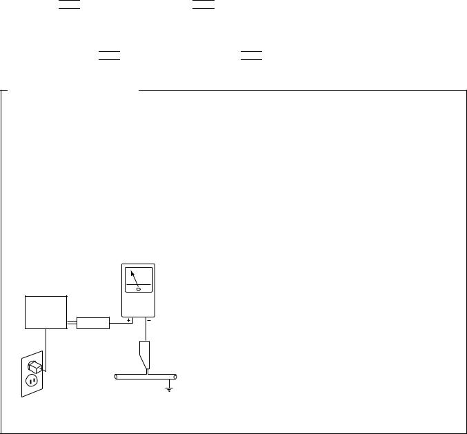
LEAKAGE CURRENT CHECK
Measure leakage current to a known earth ground (water pipe, conduit, etc.) by connecting a leakage current tester such as Simpson Model 229-2 or equivalent between the earth ground and all exposed metal parts of the appliance (input/output terminals, screwheads, metal overlays, control shaft, etc.). Plug the AC line cord of the appliance directly into a 120V AC 60Hz outlet and turn the AC power switch on. Any current measured must not exceed 0.5mA.
|
|
Reading should |
|
Leakage |
not be above |
Device |
current |
0.5mA |
under |
tester |
|
test |
|
|
Test all |
|
|
exposed metal |
|
|
surfaces |
|
|
Also test with |
|
|
plug reversed |
|
Earth |
(Using AC adapter |
|
ground |
plug as required) |
|
|
AC Leakage Test
ANY MEASUREMENTS NOT WITHIN THE LIMITS OUTLINED ABOVE ARE INDICATIVE OF A POTENTIAL SHOCK HAZARD AND MUST BE CORRECTED BEFORE RETURNING THE APPLIANCE TO THE CUSTOMER.
2. PRODUCT SAFETY NOTICE
Many electrical and mechanical parts in the appliance have special safety related characteristics. These are often not evident from visual inspection nor the protection afforded by them necessarily can be obtained by using replacement components rated for voltage, wattage, etc. Replacement parts which have these special safety characteristics are identified in this Service Manual.
Electrical components having such features are identified by marking with a  on the schematics and on the parts list in this Service Manual.
The use of a substitute replacement component which does not have the same safety characteristics as the PIONEER recommended replacement one, shown in the parts list in this Service Manual, may create shock, fire, or other hazards.
Product Safety is continuously under review and new instructions are issued from time to time. For the latest information, always consult the current PIONEER Service Manual. A subscription to, or additional copies of, PIONEER Service Manual may be obtained at a nominal charge from PIONEER.
2
X-HMD01, X-HMD03, X-HX99, X-HX05
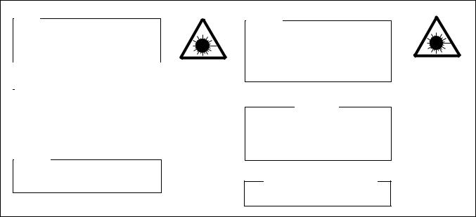
VARO!
AVATTAESSA JA SUOJALUKITUS OHITETTAESSA OLET ALTTIINA NÄKYMÄTTÖMÄLLE LASERSÄTEIYLLE. ÄLÄ KATSO SÄTEESEEN.
|
|
|
|
|
LASER |
|
|
|
|
|
kuva 1 |
|
|
|
|
|
Lasersateilyn |
|
ADVARSEL : |
|
|
|
varoitusmerkki |
|
|
|
|
||
|
USYNLIG LASERSTRÅLING VED ÅBNING |
|
|
||
|
NÅR SIKKERHED SAFBRYDERE ER UDE AF |
|
|||
|
FUNKTION. UNDGÅ UDSÆTTELSE |
FOR |
|
||
|
STRÅLING. |
|
|
|
|
|
|
|
|
|
|
VARNING!
OSYNLIG LASERSTRÅLNING NÄR DENNA DEL ÄR ÖPPNAD OCH SPÄRREN ÄR URKOPPLAD. BETRAKTA EJ STRÅLEN.
WARNING!
DEVICE INCLUDES LASER DIODE WHICH EMITS INVISIBLE INFRARED RADIATION WHICH IS DANGEROUS TO EYES. THERE IS A WARNING SIGN ACCORDING TO PICTURE 1 INSIDE THE DEVICE CLOSE TO THE LASER DIODE.
IMPORTANT
THIS PIONEER APPARATUS CONTAINS LASER OF CLASS 1.
SERVICING OPERATION OF THE APPARATUS SHOULD BE DONE BY A SPECIALLY INSTRUCTED PERSON.
LASER DIODE CHARACTERISTICS MAXIMUM OUTPUT POWER : 5 mw WAVELENGTH : 780-785 nm
LASER
Picture 1 Warning sign for laser radiation
3
X-HMD01, X-HMD03, X-HX99, X-HX05
2. EXPLODED VIEWS AND PARTS LIST
∙
∙The  mark found on some component parts indicates the importance of the safety factor of the part. Therefore, when replacing, be sure to use parts of identical designation.
∙Screws adjacent to  mark on the product are used for disassembly.
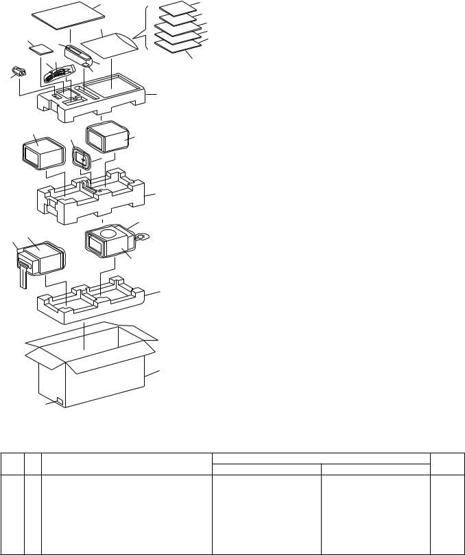
2.1PACKINGParts marked by "NSP" are generally unavailable because they are not in our Master Spare Parts List.NOTES:
2.1.1 X-HMD01 and X-HMD03
|
20 |
29 |
|
|
15 |
|
23 |
11 |
|
12 |
|
5 |
|
|
6 |
13 |
|
|
|
|
22 |
9 |
14 |
|
25 |
|
|
7 |
|
10
16
(1) PACKING PARTS LIST
Mark |
No. |
Description |
|
Part No. |
NSP |
1 |
MD Recorder |
|
See Contrast table (2) |
NSP |
2 |
CD Receiver |
|
See Contrast table (2) |
NSP |
3 |
Speaker System (L ch) |
|
See Contrast table (2) |
NSp |
4 |
Speaker System (R ch) |
|
See Contrast table (2) |
|
5 |
Sound Scape Disc |
|
See Contrast table (2) |
|
6 |
Remote Control Unit |
|
60231A |
|
|
(REA-22C) |
|
|
|
7 |
Remote Control Battery Cover |
60231-1 |
|
|
8 |
AM Loop Antenna |
60232 |
|
|
9 |
CD/MD Cable |
60233 |
|
|
3 |
8 |
3 or 4 |
10 |
Dry Cell Battery (AA, R6P) |
60235 |
|
|
|
11 |
Operating Instructions (CD) |
66780-CDU |
|||
|
|
|
|
||||
|
|
|
|
|
(English) |
|
|
|
|
24 |
|
12 |
Operating Instructions (CD) |
66780-CDC |
|
|
|
|
|
(Chinese) |
|
||
|
|
|
|
|
|
||
|
|
|
|
13 |
Operating Instructions (MD) |
66780-MDU |
|
|
|
|
17 |
|
(English) |
|
|
|
|
|
14 |
Operating Instructions (MD) |
66780-MDC |
||
|
|
|
|
||||
|
|
|
|
|
(Chinese) |
|
|
|
|
|
27 |
15 |
Initial Instruction Manual |
66783 |
|
|
|
|
|
|
|
||
|
1 |
|
|
16 |
Polyform (TOP) |
66753 |
|
26 |
|
|
17 |
Polyform (MIDD) |
66754 |
||
|
|
|
|||||
|
|
|
|
18 |
Polyform (BOTTOM) |
66755 |
|
|
|
|
2 |
19 |
Display Carton |
See Contrast table (2) |
|
|
|
|
20 |
Carton Paper |
66782 |
||
|
|
|
|
21 |
• • • • • |
|
|
|
|
|
18 |
22 |
Polybag |
53110 |
|
|
|
|
23 |
Polybag |
53117 |
||
|
|
|
|
||||
|
|
|
|
24 |
Polybag |
53101 |
|
|
|
|
|
25 |
Polybag |
53110 |
|
|
|
|
|
26 |
Mirror Mat (MD) |
66694 |
|
|
|
|
|
27 |
Mirror Mat (CD) |
66794 |
|
|
|
|
|
28 |
JAN Cord Label |
See Contrast table (2) |
|
|
|
|
|
29 |
Safety Directions |
See Contrast table (2) |
|
|
|
|
19 |
|
|
|
|
|
28 |
|
|
|
|
||
(2) CONTRAST TABLE |
|
|
|
|
|||
X-HMD01 and X-HMD03 are constructed the same except for the following : |
|
|
|||||
Mark No. |
Symbol and Description |
Part No. |
Remaks |
||||
X-HMD01 |
X-HMD03 |
||||||
|
|
|
|
|
|||
NSP |
1 |
MD Recorder |
|
MJ-HMD01 |
MJ-HMD03 |
|
|
NSP |
2 |
CD Receiver |
|
XC-HMD01 |
XC-HMD03 |
|
|
NSP |
3 |
Speaker System (L ch) |
|
S-HMD01LR |
S-HMD03L |
|
|
NSP |
4 |
Speaker System (R ch) |
|
S-HMD01LR |
S-HMD03R |
|
|
|
5 |
Sound Scape Disc |
|
60234-01 |
60234-03 |
|
|
|
19 |
Display Carton |
|
66781-01B |
66781-03B |
|
|
|
28 |
JAN Cord Seal |
|
66790-01B |
66790-03B |
|
|
|
29 |
Safety Directions |
|
66784-01B |
66784-03B |
|
|
4

X-HMD01, X-HMD03, X-HX99, X-HX05
2.1.2 X-HX99 and X-HX05
11
|
|
17 |
14 |
|
|
3 |
|
|
4 |
6, 7 |
13 |
|
|
|
5 18 |
|
|
8
2
15
2
1
9
16
10
(1) PACKING PARTS LIST
Mark |
No. |
Description |
|
Part No. |
NSP |
1 |
CD Receiver |
|
See Contrast table (2) |
NSP |
2 |
Speaker System |
|
See Contrast table (2) |
|
3 |
Remote Control Unit |
|
60231A |
|
|
(REA-22C) |
|
|
|
4 |
AM Loop Antenna |
60232 |
|
|
5 |
Dry Cell Battery (AA, R6P) |
60235 |
|
|
6 |
Operating Instructions (CD) |
|
66780-CDU |
|
|
(English) |
|
|
|
7 |
Operating Instructions (CD) |
|
66780-CDC |
|
|
(Chinese) |
|
|
|
8 |
Polyform B (TOP) |
66682 |
|
|
9 |
Polyform B (BOTTOM) |
66683 |
|
|
10 |
Display Carton |
|
See Contrast table (2) |
|
11 |
Carton Sheet B |
66678 |
|
|
12 |
• • • • • |
|
|
|
13 |
Polybag |
53117 |
|
|
14 |
Polybag |
53101 |
|
|
15 |
Mirror Mat (CD) |
66794 |
|
|
16 |
POS Code Seal |
|
See Contrast table (2) |
|
17 |
Safety Directions |
|
See Contrast table (2) |
|
18 |
Remote Control Battery Cover |
60231-1 |
|
(2) CONTRAST TABLE
X-HX99 and X-HX05 are constructed the same except for the following :
Mark |
No. |
Symbol and Description |
Part No. |
|
Remaks |
|
X-HX99 |
X-HX05 |
|||||
|
|
|
|
|||
NSP |
1 |
CD Receiver |
XC-HX99 |
XC-HX05 |
|
|
NSP |
2 |
Speaker System |
S-HX99-LR |
S-HX05-LR |
|
|
|
10 |
Display Carton |
66677-99B |
66677-05B |
|
|
|
16 |
POS Code Seal |
66668-99B |
66668-05B |
|
|
|
17 |
Safety Directions |
66784-99B |
66784-05B |
|
|
|
|
|
|
|
|
5
X-HMD01, X-HMD03, X-HX99, X-HX05
2.2 MD RECORDER SECTION
39
40
41
|
|
|
B |
8 |
|
|
|
|
|
|
38 |
|
|
|
|
|
|
|
|
|
42 |
8 |
|
|
|
|
|
|
|
|
|
|
|
||
|
|
|
|
|
|
|
|
|
|
|
|
|
|
8 |
|
|
|
|
|
32 |
|
|
|
|
|
|
|
|
|
|
|
43 |
|
|
|
|
|
32 |
|
|
44 |
|
|
|
|
|
|
|
45 |
|
|
|
|
|
|
|
|
|
|
|
|
|
|
|
|
|
A |
|
|
|
|
|
|
9 |
32 |
|
46 |
|
|
|
|
|
9 |
|
|
|
|
||
|
|
32 |
|
|
|
|
|
|
|
|
|
|
|
|
|
|
|
|
|
32 |
|
|
|
|
|
|
|
|
|
37 |
|
|
|
|
|
|
|
|
36 |
|
8 |
|
|
|
|
|
|
|
|
|
|
|
|
|
|
|
35 |
|
|
|
|
|
|
|
|
|
|
8 |
|
8 |
|
|
|
|
|
|
|
8 |
|
|
|
|
|
|
|
|
|
8 |
|
|
|
|
15 |
|
|
|
|
|
|
|
|
|
|
|
17 |
|
|
|
|
11 |
14 |
|
16 |
|
|
|
|
|
|
|
|
|
|
||
|
|
12 |
13 |
|
|
|
|
|
|
|
10 |
|
|
31 |
|
|
|
9 |
|
18 |
8 |
|
|
|
A |
|
|
|
|
|
|
|
|
B |
|
8 |
|
|
|
|
|
|
40 |
|
7 |
4 |
|
19 |
|
|
|
|
|
|
|
9 |
|
|
|
|
|
|
5 |
|
|
|
|
|
|
|
|
|
|
20 |
|
|
|
44 |
|
|
6 |
|
|
|
|
50 |
|
|
|
|
|
|
|
8 |
|
|
|
|
3 |
|
|
|
|
|
33 |
34 |
|
|
23 |
22 |
|
|
|
|||
|
|
|
|
|
34 |
|
||
|
|
23 |
|
|
|
|
||
|
|
|
|
|
49 |
29 |
|
|
|
|
|
26 |
|
|
34 |
|
|
|
|
|
|
|
|
|
||
|
|
|
9 |
|
|
|
|
|
|
|
|
|
27 |
|
|
|
|
|
|
|
|
25 |
28 |
|
|
|
|
|
|
|
|
|
|
|
|
1 |
|
|
|
48 |
21 |
|
|
|
47 |
|
2 |
24 |
|
Refer to |
|
|
|
|
|
"2.3 MD MECHA.(1/2)" |
|
|||||
|
|
|
|
|
||||
"2.4 MD MECHA.(2/2)".
30
34
34
34
6

X-HMD01, X-HMD03, X-HX99, X-HX05
(1) MD RECORDER SECTION PARTS LIST
Mark |
No. |
Description |
|
Part No. |
NSP |
1 |
Front Cover (MD) |
|
See Contrast table (2) |
NSP |
2 |
Front Door (MD) |
|
See Contrast table (2) |
|
3 |
Button B (MD) |
|
See Contrast table (2) |
|
4 |
Lens |
|
66734-MD |
|
5 |
Cushion A |
66795 |
|
|
6 |
Door Shaft A |
66746 |
|
|
7 |
Dumper Gear |
60227 |
|
|
8 |
Screw PAN TAPP. T3×10 |
|
PMZ30P100FNI |
|
9 |
Plate Nut |
66741 |
|
|
10 |
MD Front Case |
|
See Contrast table (2) |
|
11 |
Button D (REC) |
|
See Contrast table (2) |
|
12 |
LCD Window |
66735 |
|
|
13 |
LCD Assy |
52715 |
|
|
14 |
LCD Sheet |
66756 |
|
|
15 |
LCD Holder |
66727 |
|
|
16 |
MD COMBI PCB Assy |
|
66785C |
|
|
(LED PCB) |
|
|
|
17 |
MD COMBI PCB Assy |
|
66785A |
|
|
(FRONT PCB) |
|
|
|
18 |
Push Door Lock |
60226 |
|
|
19 |
Eject Button |
|
See Contrast table (2) |
|
20 |
Button C (MD EDIT) |
|
See Contrast table (2) |
|
21 |
MD Mecha. (KMK-260) |
61416 |
|
|
22 |
Front Door Spring |
66748 |
|
|
23 |
Screw PAN TAPP. T2×8 |
|
PBZ20P080FMC |
|
24 |
Inner Panel (MD) |
|
See Contrast table (2) |
|
25 |
MD Door |
66732 |
|
|
26 |
MD Door Shaft |
66750 |
|
|
27 |
MD Door Spring |
66751 |
|
|
28 |
Screw PAN M3×6 |
|
PMZ30P060FZK |
Mark |
No. |
Description |
|
29 |
Screw BIND TAPP. M3×6 |
|
30 |
Shield Case (Bottom) |
|
31 |
Shield Case (Up) |
|
32 |
Screw PLAT M3×6 |
|
33 |
MD COMBI PCB Assy |
|
|
(AD/DA PCB) |
|
34 |
Screw PAN M2×4 |
|
35 |
Screw PAN M3×10 |
|
36 |
Leg Rubber (A, B) |
|
37 |
Foot (A, B) |
|
38 |
MD Rear Case |
|
39 |
12P Connector Holder A |
NSP |
40 |
12P Connector Assy |
|
41 |
12P Connector Holder B |
|
42 |
Wire Clamper |
|
43 |
10P Connector Holder A |
NSP |
44 |
10P Connector Assy |
|
45 |
10P Connector Holder B |
|
46 |
Back Plate (MD) |
|
47 |
Front Door Assy (MD) |
|
48 |
Panel Tape B |
|
49 |
16P FFC (SUMI Card) |
|
50 |
19P FFC (SUMI Card) |
Part No.
BMZ30P060FZK
66739
66738
CMZ30P060FNI
66785B
PMZ20P040FZK
PBZ30P100FMC See Contrast table (2) See Contrast table (2) See Contrast table (2)
66728
66763
66729
66726
66730
66778
66731
See Contrast table (2) See Contrast table (2) 66761
66775
66776
(2) CONTRAST TABLE
X-HMD01 and X-HMD03 are constructed the same except for the following :
Mark |
No. |
Symbol and Description |
Part No. |
|
Remaks |
|
X-HMD01 |
X-HMD03 |
|||||
|
|
|
|
|||
NSP |
1 |
Front Cover A |
66714-01M |
Not used |
|
|
NSP |
1 |
Front Cover B |
Not used |
66715-03M |
|
|
|
2 |
Front Door A |
66708-01M |
Not used |
|
|
|
2 |
Front Door B |
Not used |
66709-03M |
|
|
|
3 |
Button B (MD) |
66717-01M |
66717-03M |
|
|
|
10 |
MD Front Case |
66702-01 |
66702-03 |
|
|
|
11 |
Button D (REC) |
66791-01R |
66719-03R |
|
|
|
19 |
Eject Button |
66721-01 |
66721-03 |
|
|
|
20 |
Button C (MD EDIT) |
66718-01ME |
66718-03ME |
|
|
|
24 |
Inner Panel (MD) |
66711-01M |
66711-03M |
|
|
|
36 |
Leg Rubber A |
66758-01 |
Not used |
|
|
|
36 |
Leg Rubber B |
Not used |
66759-02 |
|
|
|
37 |
Foot A |
66722-01 |
Not used |
|
|
|
37 |
Foot B |
Not used |
66723-03 |
|
|
|
38 |
MD Rear Case |
66704-01 |
66704-03 |
|
|
|
46 |
Back Plate (MD) |
66762-01B |
66762-03B |
|
|
|
47 |
Front Door A Assy (MD) |
10000-01M |
Not used |
|
|
|
47 |
Front Door B Assy (MD) |
Not used |
10100-03M |
|
|
|
|
|
|
|
|
7
X-HMD01, X-HMD03, X-HX99, X-HX05
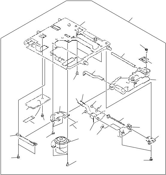
2.3 MD MECHA. (1/2 : LOADING ASSY) SECTION
13
12
11
15 |
19 |
20 |
|
14
21
Refer to
"2.4 MD MECHA. (2/2 : MECHA. ASSY)".
16 |
|
17 |
|
|
33 |
|
|
13 |
|
|
12 |
|
|
22 |
10 |
|
11 |
9 |
|
18 |
|
|
23 |
8 |
|
24 |
7 |
|
|
|
26 |
|
32 |
|
|
|
6 |
|
|
4 |
|
 31 3
31 3
5
27
2 1
30
2
∙ MD MECHA. (1/2 : LOADING ASSY) SECTION PARTS LIST
Mark No. |
Description |
|
Part No. |
Mark No. |
Description |
|
Part No. |
||
|
1 |
Motor Plate Assy |
|
X-2646-247-1 |
|
18 |
Mode Cam |
|
2-646-560-01 |
2 |
Screw +P2.6×4.5 Type3 |
7-627-854-28 |
19 |
Head Flexible Cable |
1-669-181-11 |
||||
3 |
L-SW PCB |
1-668-261-11 |
20 |
Screw +P1.7×2.5Type2 |
2-627-529-01 |
||||
4 |
Flexible Cable (6P) |
1-783-386-11 |
21 |
Overwrite Head for MD |
1-500-518-12 |
||||
5 |
Gear (Joint B) |
2-646-555-02 |
22 |
Double Sided Paper |
2-646-549-02 |
||||
6 |
Gear (Joint A) |
2-646-554-01 |
23 |
MD Mount |
|
A-4917-020-A |
|||
7 |
Slot Frame Assy |
|
X-2646-249-2 |
24 |
Small Screw |
2-643-228-01 |
|||
8 |
Coil Spring |
2-646-563-01 |
25 |
• • • • • |
|
|
|||
|
|
(Slot Arm) |
|
|
26 |
Coil Spring |
2-646-545-01 |
||
9 |
Slot Arm |
2-646-556-01 |
|
|
(Door Arm) |
|
|
||
10 |
Load Frame Assy |
|
X-2646-248-2 |
27 |
Main Frame |
2-646-547-02 |
|||
11 |
Insulator |
2-646-548-01 |
28 |
• • • • • |
|
|
|||
12 |
Screw W2.6,Middle |
7-688-002-11 |
29 |
• • • • • |
|
|
|||
13 |
Screw |
4-628-167-01 |
30 |
Loading Motor Assy |
|
X-2626-328-1 |
|||
14 |
Slide Frame |
2-646-557-01 |
31 |
Screw +P1.7×1.8TYP.3 |
7-627-852-38 |
||||
15 |
Head Arm |
2-646-559-01 |
32 |
Screw +P2×3 TYP.3 |
7-627-853-37 |
||||
16 |
Coil Spring |
2-646-562-01 |
33 |
Loading Assy |
|
A-4912-117-A |
|||
|
|
(Slot Frame) |
|
|
|
|
|
|
|
17 |
Coil Spring |
2-646-561-01 |
|
|
|
|
|
||
|
|
(Head Arm) |
|
|
|
|
|
|
|
8
X-HMD01, X-HMD03, X-HX99, X-HX05
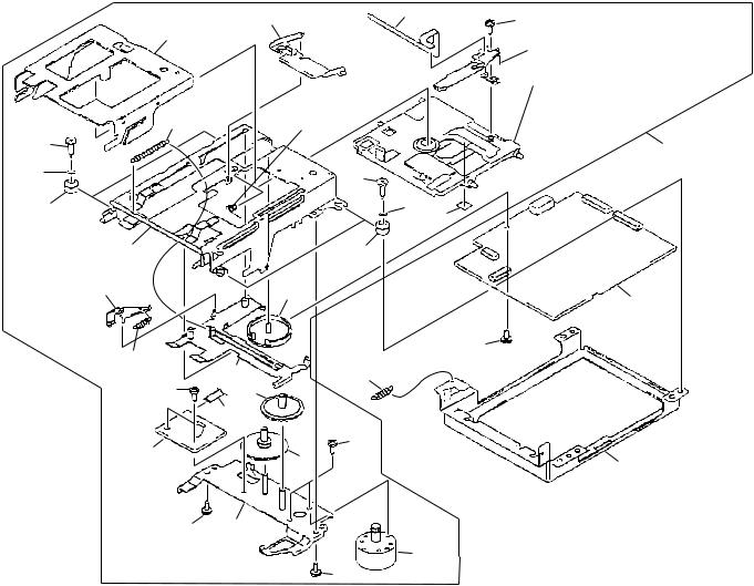
2.4 MD MECHA. (2/2 : MECHANISM ASSY) SECTION
23
6
|
|
|
12 |
|
|
|
11 |
|
|
|
13 |
|
|
|
8 |
|
1 |
|
24 |
|
|
|
|
|
9 |
|
|
|
10 |
|
|
|
|
|
15 |
7 |
|
|
14 |
5 |
15 |
|
|
|
|
20 |
|
|
|
|
|
4 |
|
|
|
3 |
|
|
21 |
|
25 |
|
|
|
16 |
|
|
2 |
|
22 |
|
|
|
||
|
|
17 |
|
4 |
19 |
|
|
|
|
||
1 |
18 |
|
1 |
|
|
∙ MD MECHA. (2/2 : MECHANISM ASSY) SECTION PARTS LIST
Mark No. |
Description |
|
Part No. |
Mark No. |
Description |
|
Part No. |
||
|
1 |
Screw Grip +P1.4×3.5 Type3 |
|
2-627-404-01 |
|
16 |
SL Motor Assy |
|
X-2626-329-1 |
2 |
Sub Guide |
2-646-453-01 |
17 |
Gear (MD) |
2-646-571-01 |
||||
3 |
Flexible Cable (7P) |
1-783-387-11 |
18 |
Screw +P1.7×4 Type3 |
7-627-852-18 |
||||
4 |
Screw +P1.4×1.8 Type3 |
7-627-850-79 |
19 |
SP Motor Assy |
|
X-2626-327-1 |
|||
5 |
D-SW PCB |
1-668-262-11 |
20 |
Lead Screw Assy |
|
X-2626-330-1 |
|||
6 |
Mechanism Chassis |
2-646-575-01 |
21 |
Lead Holder Assy |
|
X-2626-331-1 |
|||
7 |
SP Motor Fixing Plate |
2-646-566-01 |
22 |
Lead Holder (B) |
2-646-573-01 |
||||
8 |
OP Flexible Cable |
1-669-180-11 |
23 |
Deck Mechanism Assy |
|
A-4912-118-A |
|||
9 |
SL Motor Lead Wire |
1-783-318-11 |
24 |
Mini Disc Device |
|
KMS-260A |
|||
10 |
SL Motor Lead Wire |
1-783-318-21 |
|
|
KMS-260A |
|
|
||
11 |
Guide Shaft |
2-646-452-01 |
25 |
SP Tension Spring |
2-646-564-01 |
||||
12 |
Screw Grip +P1.4×1.4 Type2 |
|
2-627-530-D1 |
|
|
|
|
|
|
13 |
Rack (Insert) |
4-963-914-02 |
|
|
|
|
|
||
14 |
Pri-Load Plate |
2-646-567-01 |
|
|
|
|
|
||
15 |
Screw |
2-627-431-01 |
|
|
|
|
|
||
9
X-HMD01, X-HMD03, X-HX99, X-HX05
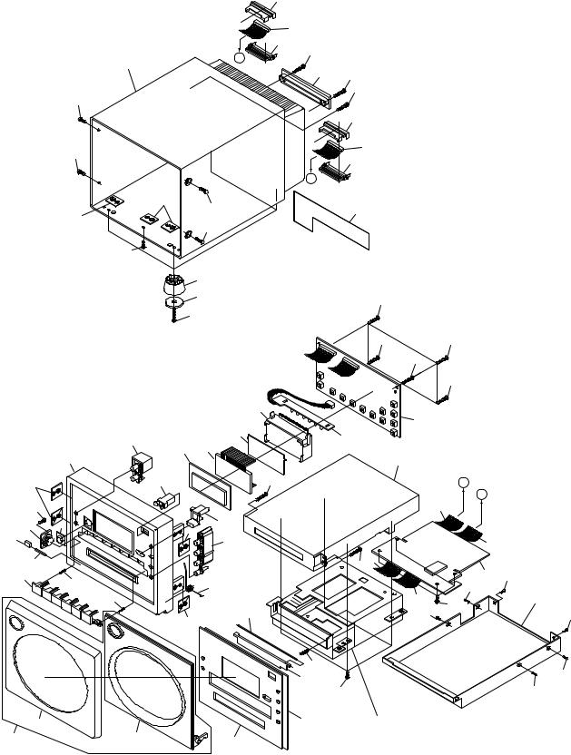
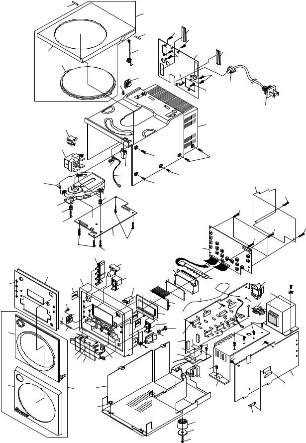
2.5 CD RECEIVER SECTION
1
17
21
57
61 |
|
|
3 |
76 |
|
57 |
55 |
|
|
|
|
59 |
58 |
77 |
42 |
|
|
3 |
|
|
43 |
|
|
24 |
|
3 |
71 |
|
|
|
|
|
3 |
|
33 |
|
|
3 |
62
50
51
52
41
69
3
3
5
66 22
4
3
16 2
1415
18
19 64
60 |
23 |
|
78 |
56
55 |
55 |
53 8
67 |
55 |
|
|
|
55 |
40 |
|
39 |
3 |
|
|
|
|
|
|
13 |
|
3 |
|
|
|
|
|
|
|
|
|
|
6 |
11 |
|
|
|
|
|
|
|
|
7 |
10 |
|
12 |
|
|
|
||
|
8 |
|
|
|
|
26 |
|
|
44 |
|
|
|
|
|
|
|
|
9 |
24 |
|
|
25 |
|
|
|
|
|
|
|
|
75 |
65 |
3 |
|
|
4 |
|
|
|
|
72 |
24 |
|
|
|
|
68 |
||
|
28 |
30 |
24 |
|
|
29 |
|
31 |
|
|
63 |
|
||
|
|
|
||
20 |
|
|
|
|
|
|
|
|
24 |
|
|
|
|
33 |
|
|
|
|
34 |
37
36
35
73
3
3
3 3
3
45
 48
48  49
49
46
 47
47
32
32
24
24
 74
74
38
70
54
10
X-HMD01, X-HMD03, X-HX99, X-HX05
(1) CD RECEIVER SECTION PARTS LIST
Mark |
No. |
Description |
|
Part No. |
|
Mark |
No. |
Description |
|
Part No. |
|
1 |
Inner Panel (CD) |
|
See Contrast table (2) |
|
39 |
CD PCB Assy |
66786 |
||
|
2 |
Dumper Gear |
60108 |
|
|
40 |
Cushion Rubber |
60230 |
||
|
3 |
Screw PAN TAPP. T3×10 |
|
PBZ30P100FZK |
|
41 |
Holder Plate |
66742 |
||
|
4 |
Plate Nut |
66741 |
|
NSP |
42 |
CD Door |
|
See Contrast table (2) |
|
|
5 |
Button C (SET) |
|
See Contrast table (2) |
NSP |
43 |
CD Door Window |
|
See Contrast table (2) |
|
|
6 |
Power Button |
|
See Contrast table (2) |
NSP |
44 |
Antenna Cord Assy |
66779 |
||
|
7 |
Button D (TIMER) |
66719 |
|
|
45 |
AM Antenna Jack |
60243 |
||
|
8 |
Push Door Lock |
60226 |
|
|
46 |
Pin Jack |
52526 |
||
|
9 |
LCD Assy (KSG4149) |
52716 |
|
|
47 |
Power Transformer |
54515 |
||
|
10 |
LCD Sheet |
66756 |
|
|
48 |
Screw BIND M4×6 |
|
BMZ40P060FMC |
|
|
11 |
LCD Holder |
66727 |
|
|
49 |
Washer |
|
WS40FMC |
|
NSP |
12 |
LED PCB Assy |
|
66788B |
|
50 |
1P Jack |
52525 |
||
|
13 |
FRONT CD PCB Assy |
|
66788A |
|
51 |
Speaker Terminal (4P) |
60246 |
||
|
14 |
Door Shaft A |
66746 |
|
|
52 |
CD Mechanism Assy |
61417 |
||
|
15 |
Screw PAN TAPP. T2×8 |
|
PBZ20P080FMC |
|
53 |
Leaf Switch |
52802 |
||
|
16 |
Cushion A |
66795 |
|
|
54 |
Fuse (F302 : 750mA/250V) |
51607 |
||
NSP |
17 |
Front Door (CD) |
|
See Contrast table (2) |
|
55 |
Screw FLAT M3×6 |
|
CMZ30P060FNI |
|
|
18 |
Button B (CD-2) |
|
See Contrast table (2) |
|
56 |
CD Rear Case |
|
See Contrast table (2) |
|
|
19 |
Button A (CD-1) |
|
See Contrast table (2) |
|
57 |
Door Shaft B |
66747 |
||
|
20 |
Lens |
|
66734-CD |
|
58 |
Rear Panel |
|
See Contrast table (2) |
|
NSP |
21 |
Front Cover (CD) |
|
See Contrast table (2) |
|
59 |
CD Door Spring |
66749 |
||
|
22 |
CD Front Case |
|
See Contrast table (2) |
|
60 |
Front Door A Assy (CD) |
|
See Contrast table (2) |
|
NSP |
23 |
CD Rear Chassis |
66737 |
|
|
60 |
Front Door B Assy (CD) |
|
See Contrast table (2) |
|
|
24 |
Screw BIND M3×6 |
|
BMZ30P060FZK |
|
61 |
CD Door Assy |
|
See Contrast table (2) |
|
|
25 |
LCD Window |
66735 |
|
|
62 |
AC Power Cord |
50319 |
||
|
26 |
Lens (STANDBY) |
66736 |
|
|
63 |
Fuse (F301 : 5A/125V) |
51604 |
||
|
27 |
Screw BIND TAPP. T3×8 |
|
BBZ30P080FZK |
|
64 |
Button A (CD-3) |
|
See Contrast table (2) |
|
|
28 |
AMP COMBI PCB Assy |
|
66789C |
|
65 |
Button D (DISPLAY) |
|
See Contrast table (2) |
|
|
|
(HEADPHONE PCB) |
|
|
|
|
66 |
Panel Tape A |
66760 |
|
|
29 |
Front Door Spring |
66748 |
|
|
67 |
Connector Assy (2P) |
66772 |
||
|
30 |
TUNER PCB Assy |
66675 |
|
|
68 |
Fuse Label |
60224 |
||
|
31 |
AMP COMBI PCB Assy |
|
66789B |
|
69 |
Cushion Rubber |
60229 |
||
|
|
(FUSE PCB) |
|
|
|
|
70 |
Fuse Label |
60268 |
|
|
32 |
Screw BTT-S T3×8 |
|
BSZ30P080FMC |
|
71 |
Dumper Gear |
60227 |
||
|
33 |
AC Cord Bushing |
60228 |
|
|
72 |
Washer |
55003 |
||
|
34 |
Heat Sink |
66743 |
|
|
73 |
Shield Plate |
66797 |
||
|
35 |
Screw PAN M3×8 |
|
PMZ30P080FZK |
|
74 |
Hymeron |
51907 |
||
|
36 |
Leg Rubber (A, B) |
|
See Contrast table (2) |
|
75 |
Barrier Plate |
66693 |
||
|
37 |
Foot (A, B) |
|
See Contrast table (2) |
|
76 |
10P Connector Cover |
|
See Contrast table (2) |
|
|
38 |
AMP COMBI PCB Assy |
|
66789A |
|
77 |
12P Connector Cover |
|
See Contrast table (2) |
|
|
|
(POWER PCB) |
|
|
|
|
78 |
Cushion Washer |
66699 |
|
|
|
|
|
|
|
|
||||
11
X-HMD01, X-HMD03, X-HX99, X-HX05
(2) CONTRAST TABLE
X-HMD01, X-HMD03, X-HX99 and X-HX05 are constructed the same except for the following :
Mark |
No. |
Symbol and Description |
|
Part No. |
|
|
Remaks |
|
X-HMD01 |
X-HMD03 |
X-HX99 |
X-HX05 |
|||||
|
|
|
|
|||||
|
1 |
Inner Panel (CD) |
66710-01C |
66710-03C |
66710-99B |
66710-05C |
|
|
|
5 |
Button C (SET) |
66718-01S |
66718-03S |
66718-05S |
66718-05S |
|
|
|
6 |
Power Button |
66720-01 |
66720-03 |
66720-05 |
66720-05 |
|
|
NSP |
17 |
Front Door A (CD) |
66706-01C |
Not used |
66706-05C |
66706-05C |
|
|
NSP |
17 |
Front Door B (CD) |
Not used |
66707-03C |
Not used |
Not used |
|
|
|
18 |
Button B (CD-2) |
66717-01C2 |
66717-03C2 |
66717-05C2 |
66717-05C2 |
|
|
|
19 |
Button A (CD-1) |
66716-01C1 |
66716-03C1 |
66716-05C1 |
66716-05C1 |
|
|
NSP |
21 |
Front Cover A (CD) |
66712-01C |
Not used |
Not used |
Not used |
|
|
NSP |
21 |
Front Cover B (CD) |
Not used |
66713-03C |
66712-05C |
66712-05C |
|
|
|
22 |
CD Front Case |
66701-01 |
66701-03 |
66701-05 |
66701-05 |
|
|
|
36 |
Leg Rubber A |
66758-01 |
Not used |
66758-01 |
66758-01 |
|
|
|
36 |
Leg Rubber B |
Not used |
66759-02 |
Not used |
Not used |
|
|
|
37 |
Foot A |
66722-01 |
Not used |
66722-05 |
66722-05 |
|
|
|
37 |
Foot B |
Not used |
66723-03 |
Not used |
Not used |
|
|
NSP |
42 |
CD Door |
67705-01 |
67705-03 |
67705-05 |
67705-05 |
|
|
NSP |
43 |
CD Door Window |
66733-01 |
66733-03 |
66733-99B |
66733-OV |
|
|
|
56 |
CD Rear Case |
66703-01 |
66703-03 |
66703-05 |
66703-05 |
|
|
|
58 |
Rear Panel |
66740-01B |
66740-03B |
66740-99B |
66740-05B |
|
|
|
60 |
Front Door A Assy (CD) |
10200-01C |
Not used |
10200-05C |
10200-05C |
|
|
|
60 |
Front Door B Assy (CD) |
Not used |
10300-03C |
Not used |
Not used |
|
|
|
61 |
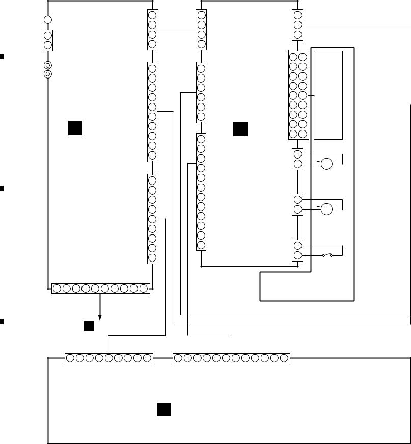
CD Door Assy |
10400-01 |
10400-03 |
10400-05 |
10400-05 |
|
|
|
64 |
Button A (CD-3) |
66716-01C3 |
66716-03C3 |
66716-05C3 |
66716-05C3 |
|
|
|
65 |
Button D (DISPLAY) |
66719-01D |
66719-03D |
66719-05D |
66719-05D |
|
|
|
76 |
10P Connector Cover |
Not used |
Not used |
66685 |
66685 |
|
|
|
77 |
12P Connector Cover |
Not used |
Not used |
66684 |
66684 |
|
12
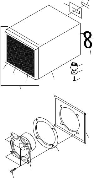
2.6 SPEAKER SYSTEM
13
2
4
5
3
1
10
7
11
14
6
8
9
12
5
X-HMD01, X-HMD03, X-HX99, X-HX05
 SPEAKER SYSTEM PARTS LIST (S-HMD01LR)
Mark |
No. |
Description |
|
Part No. |
|
1 |
Speaker Frame Assy |
10500-01 |
|
|
2 |
Speaker Frame |
66724-01 |
|
|
3 |
Grille Frame |
66725-01 |
|
|
4 |
Speaker Net |
66744-01 |
|
NSP |
5 |
Speaker Box Assy |
10600-01 |
|
|
6 |
Speaker Cord |
50318 |
|
|
7 |
Speaker Unit |
54407 |
|
|
8 |
Foot A |
66722-01 |
|
|
9 |
Leg Rubber A |
66758-01 |
|
|
10 |
Packing |
66697 |
|
|
11 |
Screw |
|
BBZ30P120FZK |
|
12 |
Screw |
|
PBZ30P120FZK |
|
13 |
Back Plate A Label |
|
66673-01B |
|
14 |
Label Plate B |
6672 |
|
 SPEAKER SYSTEM PARTS LIST
(S-HMD03L and S-HMD03R)
Mark |
No. |
Description |
|
Part No. |
|
1 |
Speaker Frame Assy L |
|
10500-03L |
|
|
(S-HMD03L) |
|
|
|
1 |
Speaker Frame Assy R |
|
10500-03R |
|
|
(S-HMD03R) |
|
|
|
2 |
Speaker Frame |
66724-03 |
|
|
3 |
Grille Frame |
66725-03 |
|
|
4 |
Speaker Net L (S-HMD03L) |
|
66744-03L |
|
4 |
Speaker Net R (S-HMD03R) |
|
66744-03R |
NSP |
5 |
Speaker Box Assy |
10600-03 |
|
|
6 |
Speaker Cord |
50318 |
|
|
7 |
Speaker Unit |
54407 |
|
|
8 |
Foot B |
66723-03 |
|
|
9 |
Leg Rubber B |
66759-02 |
|
|
10 |
Packing |
66697 |
|
|
11 |
Screw |
|
BBZ30P120FZK |
|
12 |
Screw |
|
PBZ30P120FZK |
|
13 |
Back Plate A Label |
|
66673-03B |
|
14 |
Label Plate B |
6672 |
|
 SPEAKER SYSTEM PARTS LIST
(S-HX99LR and S-HX05LR)
Mark |
No. |
Description |
|
|
Part No. |
|
1 |
Speaker Frame Assy |
10500-05 |
||
|
2 |
Speaker Frame |
66724-05 |
||
|
3 |
Grille Frame |
66725-05 |
||
|
4 |
Speaker Net (S-HX99LR) |
66744-99B |
||
|
4 |
Speaker Net (S-HX05LR) |
66744-05 |
||
NSP |
5 |
Speaker Box Assy |
10600-05 |
||
|
6 |
Speaker Cord |
50318 |
||
|
7 |
Speaker Unit |
54407 |
||
|
8 |
Foot A |
66722-05 |
||
|
9 |
Leg Rubber A |
66758-01 |
||
|
10 |
Packing |
66697 |
||
|
11 |
Screw |
BBZ30P120FZK |
||
|
12 |
Screw |
PBZ30P120FZK |
||
|
13 |
Back Plate A Label (S-HX99LR) |
66673-99B |
||
|
13 |
Back Plate A Label (S-HX05LR) |
66673-05B |
||
|
14 |
Label Plate B |
6672 |
||
13
X-HMD01, X-HMD03, X-HX99, X-HX05
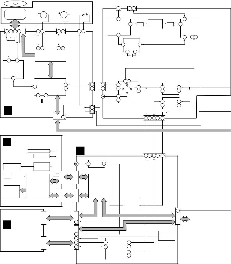
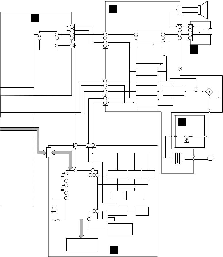
3. BLOCK DIAGRAM AND SCHEMATIC DIAGRAM
3.1 BLOCK DIAGRAM
DISC
PICKUP ASSY
CN400 |
|
|
|
1 |
4 |
9 |
10 |
D |
C |
A |
B |
|
|
|
CONTROL |
36 35
IC400
52103
(AN8806SB)
RF & SSP HEAD AMP.
10
CD
CD MECHANISM ASSY
SPINDLE |
|
SLED |
LEAF SW |
|
||
MOTOR ASSY |
MOTOR ASSY |
(INNER) |
|
|||
(AEA7009) |
(AEA7010) |
(AEA7011) |
|
|||
|
M |
|
M |
|
|
|
CN401 |
CN402 |
CN403 |
|
|
||
1 |
2 |
1 |
2 |
1 |
2 |
|
DISK+ |
DISK- |
SLED+ |
SLED- |
INNER |
|
|
11 |
12 |
13 |
14 |
|
|
|
|
IC401 |
|
|
|
|
|
|
52118 |
|
|
|
|
|
|
(BA6299FP) |
|
|
|
|
|
|
4ch BTL DRIVER |
|
|
|
|
|
|
SERIAL BUS |
|
|
|
|
|
|
IC402 |
|
|
|
CN404 |
|
|
(MN66274RHM) |
73 |
|
CD |
4 |
|
44 DSP & DF & DAC |
|
|
||||
75 R ch |
|
R ch 2 |
||||
57 |
58 |
|
|
|
|
LINE-IN |
|
|
|
|
(AUX) |
||
|
|
|
|
|
|
|
FM |
AM LOOP |
ANTENNA |
ANTENNA |
|
CN1 |
|
|
|
CN2 |
|
|
|
|
|
|
|
|
|
|
FM |
|
|
AM |
|
|
|
|
|
|
AM |
|
|
|
|
|
|
|
|
|
|
|
|
|||
|
|
7 |
|
|
|
|
|
Q1 |
|
|
|
20 |
IC2 |
|
|
U1 |
|
|
|
|
|
FM |
|
|
|||
|
(TFFJ2U) |
|
1 |
FIL3 |
|
(2SC2412K) |
FIL4 |
|
1 |
52190 |
|||
|
|
|
|
|
|
IF AMP. |
|
|
|
(BA1450S) |
|||
|
FM TUNER PACK |
|
|
|
|
|
|
||||||
|
|
|
|
|
|
|
|
FM : IF/DET/MPX |
|||||
|
|
|
|
|
|
|
|
|
|
|
|
||
|
|
4 |
|
|
|
|
|
|
|
|
|
AM : RF/IF/DET |
|
|
|
|
|
|
|
|
|
|
|
|
13 |
11 10 |
|
|
|
|
|
IC3 |
|
|
|
|
|
|
|
||
|
|
|
|
|
|
|
|
|
|
|
|
TUNER |
|
|
|
15 |
52193 |
7 |
BAND |
|
BAND |
||||||
|
|
(BU2614) |
|
|
|
|
|
|
|
|
|||
|
|
TUNER PLL |
|
|
|
|
|
|
|
|
|||
|
|
|
1 |
2 |
|
|
|
|
|
|
|
|
|
|
|
|
|
|
X1 |
|
|
|
|
|
|
|
|
|
|
|
|
75kHz |
|
|
|
|
|
|
|
|
|
|
CN100 |
TUNER |
R ch |
|
|
|
|
|
|
|
|
|
|
|
15 |
2 |
|
|
|
|
|
|
|
|
|
||
4 |
CD |
11 |
|
|
AUDIO |
|
IC101 |
|
|
AUDIO |
|||
|
|
|
|
|
|
||||||||
2 |
R ch |
4 |
|
|
13 |
|
REC |
14 |
15 |
||||
|
|
|
(TC9260P) |
|
|
||||||||
|
|
4 R ch |
R ch 3 |
|
2 R ch |
MD |
|||||||
|
|
|
|
|
S VOL. |
|
|||||||
|
AUX |
12 |
|
|
|
|
MD |
|
|
|
|
|
|
|
|
|
|
|
|
SYS |
|
|
|
X400 |
|||||
B CD PCB |
16.934MHz |
- |
|||||
CD |
|||||||
|
|
|
|
|
|||
|
|
|
|
|
|
||
|
CN406 |
||
|
|
12 |
|
H FRONT MD PCB |
|
||
|
BACK-LIGHT LED |
|
|
|
KEY LED |
|
|
SCAPE - LED |
Q901 - Q905 |
CD REC |
|
IN |
|||
DTC114YK |
|||
1 |
|
||
LED DRIVER |
|
||
|
|
||
KEY |
|
|
|
|
IC900 |
CN902 |
|
LC900 |
52182 (NJU6408B) |
||
LCD DRIVER |
|
||
52715 |
|
||
|
|
||
(KSG4148S) |
|
|
|
LCD PANEL |
|
|
|
|
|
CN903 |
|
|
CN102 |
|
|
I |
|
|
|
MD MOUNT
CN103
14
|
J100 R ch |
1 |
|
|
|
CN405 |
|
IC100 |
REC |
|
|
+9V |
1 |
(TC4052BP) |
|
||
+5V |
4 |
FUNCTION |
MD |
chR |
|
SELECTOR |
|||||
|
|
|
|
||
|
|
|
CN101 |
8 |
|
|
|
|
10 |
R ch
CN807 |
|
|
|
|
CN806 |
||
|
|
|
|
REC |
|||
|
1 |
IC803 2 |
|
|
|||
|
|
|
|
|
|
MD |
|
|
|
IC800 |
|
|
|
|
|
CN802 |
52181 |
|
|
|
|
||
|
|
(CXP84632-1) |
|
|
|
||
|
|
SUB. CPU |
|
|
|
||
CN803 |
|
|
Q803 - Q807 |
||||
|
|
(2SA1037K, |
|||||
|
|
|
|
2SC2412K) |
|||
|
CN801 |
|
|
+3.3V REG. |
|||
7 |
POWER DOWN |
|
|
|
|
||
|
|
|
|
|
|
||
12 |
512FS |
|
|
|
|
|
|
17 |
|
|
IC801 |
|
|
||
|
MD |
MD |
|
|
MD |
||
5 |
15 |
52186 |
19 |
||||
|
|
|
|||||
1 |
|
|
12 |
(AK4518-VF-E2) |
20 R ch |
||
|
CN804 |
|
|
AD/DA CON. |
|
MD REC |
|
|
|
|
|
6 |
|||
|
|
|
|
|
|||
|
|
|
|
|
|
||
|
|
|
|
|
3 R ch |
||
|
MD |
14 |
IC103 |
MD |
|
|
(TC9260P) |
15 |
|
|
R ch |
3 |
2 R ch |
|
|
MD VOL. |
|||
MD |
ch |
|
+9V |
|
|
R |
|
|
|
7 |
5 |
4 |
|
|
|
R ch |
MD |
+9V |
CN805
MD +5V 10
10
POWER PCB
CN301
IC802
(TC7SU04F)
X'TAL OSC.
X-HMD01, X-HMD03, X-HX99, X-HX05
C POWER PCB
A TUNER PCB
J301
AUDIO
SPEAKER
|
|
|
|
CN103 |
|
|
|
|
|
|
|
|
|
|
|
|
|
|
|
|
|
|
|
|
CD + 9V |
5 |
|
|
|
|
|
|
|
|
|
|
|
|
4 |
|
4 |
|
|
|
|
|
CD + 9V |
7 |
|
|
|
|
CN300 |
AUDIO |
|
IC300 |
|
|
3 |
R ch |
3 |
PHONES |
|||
AUDIO |
|
|
|
AUDIO |
|
|
|
|
|
|
AUDIO |
|
|
AUDIO |
|
|
|
||||
31 |
|
24 |
8 |
|
|
|
8 |
|
8 |
11 |
5 |
|
5 |
|
|||||||
|
2 |
|
10 R ch |
10 |
|
|
|
R ch 10 |
|
|
R ch |
5 |
52115 |
2 |
|
2 |
|
2 |
|
||
|
IC102 |
R ch |
|
|
|
(BA5412) |
R ch |
R ch |
|
||||||||||||
R ch |
(BH3854AS) |
|
|
|
|
|
5 |
|
CD + 9V |
|
|
|
POWER AMP. |
|
CN304 |
|
CN305 |
||||
|
|
MAIN VOL. |
DATA |
|
|
|
|
|
CD + 9V |
|
|
|
|
|
|
||||||
|
|
8 |
|
|
|
7 |
|
|
|
|
|
|
|
|
|
|
|
||||
|
|
|
10 |
|
|
|
|
|
|
|
|
|
|
|
|
|
|
E |
|||
|
|
|
|
CN102 |
|
|
|
|
|
|
|
|
Q300 : 2SA933AS |
|
|
|
|
||||
|
|
|
|
|
|
|
|
|
|
|
|
|
|
Q301 : 2SC1740S |
|
|
|
|
|||
|
|
|
|
|
|
|
|
|
|
|
|
|
|
Q305 : 2SA933AS |
|
|
|
|
HEADPHONE |
||
|
|
|
|
|
|
|
|
|
|
|
|
|
|
|
|
|
|
|
|
||
|
|
|
|
|
|
|
|
|
|
|
|
|
|
POWER AMP. CONT. |
|
|
|
|
PCB |
||
|
|
|
|
|
|
|
|
|
|
|
|
|
|
(ST-BY) and (MUTE) |
|
|
|
|
|||
|
|
|
|
|
|
|
|
|
|
|
|
|
|
|
|
|
|
|
|
||
|
|
|
|
|
|
|
|
|
|
|
|
|
|
|
|
|
J303 |
CD-MD OUTPUT |
|||
|
|
|
|
|
|
|
|
|
|
|
|
|
|
|
Q315 |
|
|
|
|||
|
|
|
|
|
|
|
|
|
|
|
|
|
|
|
|
|
|
(TX-OUT) |
|
||
|
|
|
|
|
|
|
|
|
|
|
|
|
|
|
2SD2061F |
|
|
|
|
||
|
|
|
|
|
|
|
|
|
|
|
|
|
|
|
|
|
|
|
|
|
|
|
|
|
|
|
|
|
|
|
|
CN302 |
|
|
|
CD + 9V |
|
|
|
|
|
|
|
|
|
|
|
|
|
|
|
|
|
|
|
Q313 : 2SB1370F |
|
|
|
|
|
|
|||
|
|
|
|
|
|
|
|
|
|
|
TUNER/CD + 9V |
|
|
|
|
|
|
|
|||
|
|
|
|
|
|
|
|
|
4 |
|
|
Q314 : 2SC1740S |
|
|
|
|
|
|
|||
|
|
|
|
|
|
|
|
|
|
|
|
|
|
|
|
|
|
D310 - D313 |
|||
|
|
|
|
|
|
|
|
|
1 |
|
COM + 5V |
|
|
TUNER/CD + 9V |
|
|
|
|
|
||
|
|
|
|
|
|
|
|
|
|
|
|
|
Q309 : 2SB1370F |
|
Q311,Q312 |
|
|
(MTZJ10A) |
|||
|
|
|
|
|
|
|
|
|
|
|
MD + 5V |
|
|
|
|
|
18V |
||||
|
|
|
|
|
|
|
|
|
10 |
|
|
Q310 : 2SC1740S |
|
2SA933S |
|
|
|||||
|
|
|
|
|
|
|
|
|
CN301 |
|
|
|
|
|
|
||||||
|
|
|
|
|
|
|
|
|
|
|
|
|
|
MD + 5V |
|
P-MUTE |
|
|
|
||
|
|
|
|
|
|
|
|
|
9 |
|
CD + 9V |
|
|
Q302 : 2SB1370F |
|
|
|
|
|
|
|
|
|
|
|
|
|
|
|
|
|
|
|
|
|
|
|
|
|
|
|||
|
|
|
|
|
|
|
|
|
12 |
COM + 5V |
|
|
Q303 : 2SA933AS |
|
|
|
|
|
|
||
|
|
|
|
|
|
|
|
|
|
|
|
Q304 : 2SC1740S |
|
|
|
|
|
|
|||
|
|
|
|
|
|
|
|
|
|
|
|
|
|
|
|
|
|
|
|
||
|
|
|
|
|
|
|
|
|
|
CN303 |
|
|
|
COM + 5V |
|
|
|
|
|
TM4 |
|
|
|
|
|
|
|
|
|
|
|
|
|
|
|
|
|
|
|
|
|
|
|
|
|
|
|
|
|
|
|
|
|
|
|
|
|
|
|
|
|
D |
|
|
|
|
|
|
|
|
|
|
|
|
|
|
|
|
|
|
|
|
|
FUSE PCB |
|||
|
|
|
|
|
|
|
|
|
|
|
|
|
|
|
|
|
TM3 |
TM5 |
|
|
TM6 |
|
|
|
|
|
|
|
|
|
|
|
|
|
|
|
|
|
|
|
|
|
F301 |
|
|
|
|
|
|
|
|
|
|
|
|
|
|
|
|
|
|
|
|
5A/125V |
|
|
|
|
|
|
|
7 |
4 |
|
1 |
|
|
|
|
|
|
|
|
|
|
(51604) |
|
|
|
|
CN501 |
CN502 |
DATA |
CD+ 9V |
COM+ 5V |
CN503 |
|
|
|
|
|
|
|
|
|
|
|
|
|
|
|
|
CD - SYS |
|
|
|
|
|
|
|
|
|
|
|
E304 |
LIVE |
|||||
|
|
|
|
|
|
|
|
|
|
|
|
|
|
|
|
|
|
|
|
|
AC IN |
|
|
|
|
|
|
|
|
|
|
|
|
|
|
|
|
|
|
|
E303 |
NEUTRAL |
|
|
|
|
|
|
|
|
|
|
|
|
|
|
|
|
|
|
POWER |
|
|
|
|
|
|
|
|
|
|
28 |
|
70 |
|
|
|
|
|
|
|
TRANSFORMER |
|
|
|||
|
|
|
|
|
|
|
|
Q505,Q507,Q510 |
Q511,Q512 |
Q511,Q512 |
|
|
|
|
|
|
|||||
|
|
|
|
92 |
|
|
|
|
|
|
|
|
|
|
|
|
|||||
|
|
|
X500 |
|
|
|
72 71 75 |
|
DTC114YK |
|
2SC2412K |
2SC2412K |
|
|
|
|
|
|
|||
|
|
|
|
|
|
|
|
|
|
|
|
|
|
|
|||||||
|
|
|
32kHz |
|
|
|
|
|
|
|
LED DRIVER |
|
PS DET0 |
PS DET0 |
|
|
|
|
|
|
|
|
|
|
93 |
|
|
|
|
|
|
|
|
|
|
|
|
|
|
|
|
|
|
|
|
|
|
|
|
|
|
|
|
|
|
|
|
|
|
|
|
|
|
|
|
|
|
|
X501 |
39 |
|
|
|
|
|
|
|
|
|
|
|
|
|
|
|
|
|
|
|
|
|
|
|
|
|
|
|
|
|
|
|
|
|
|
|
|
|
|
|
|
|
4.19MHz |
|
|
|
IC501 |
|
|
|
|
|
|
|
|
|
|
|
|
|
|
|
|
|
|
|
40 |
|
|
52206 |
|
|
|
|
|
BACK-LIGHT |
|
|
|
|
|
|
||
|
|
|
|
|
(CXP83232A-111Q) |
|
|
KEY LED |
|
|
|
|
|
|
|
||||||
|
|
|
|
2 |
|
|
|
LED |
|
|
|
|
|
|
|
||||||
|
|
|
|
|
|
SYSTEM |
|
|
|
|
|
|
|
|
|
|
|
|
|||
|
|
|
|
|
|
|
|
|
|
|
|
|
|
|
|
|
|
|
|
||
|
|
|
|
|
|
MICROCOM. |
|
|
|
|
|
|
|
|
|
|
|
|
|
|
|
|
|
|
CN500 |
|
|
|
|
|
|
|
|
|
|
|
|
|
|
|
|
|
|
|
|
|
|
|
|
|
|
|
|
|
Q501,Q503 |
|
|
DISC-LED |
|
|
|
|
|
|
|
|
|
|
|
|
|
|
|
|
74 73 |
|
DTC114YK |
|
|
|
|
|
|
|
|
||
|
|
|
|
|
|
|
|
|
|
|
|
1 - 3 |
|
|
|
|
|
|
|||
|
|
|
CN506 |
|
|
|
|
|
|
LED DRIVER |
|
|
|
|
|
|
|
|
|||
|
|
|
|
|
|
|
|
|
|
|
|
|
|
|
|
|
|
|
|||
|
|
|
|
|
|
|
|
|
|
|
|
|
|
|
|
|
|
|
|
||
|
|
|
|
|
|
|
3 |
|
|
KEY |
|
|
|
|
|
|
|
|
|
|
|
|
|
|
SW519 |
|
|
|
|
|
|
IC500 |
|
|
|
|
|
|
|
|
|
|
|
|
|
DOOR SW |
|
|
|
|
|
|
|
|
|
|
|
|
|
|
|
|
|||
|
|
|
|
|
|
|
|
|
|
|
60124 (SPS-442-1-W) |
|
|
|
|
|
|
|
|
||
|
|
|
|
|
|
|
|
|
|
|
REMOTE CONTROL |
|
|
|
|
|
|
|
|
||
|
|
|
|
|
|
|
|
|
|
|
RECEIVER |
|
|
|
|
|
|
|
|
|
|
|
|
|
|
|
|
LCD500 |
|
|
|
|
|
|
|
|
|
|
|
|
|
|
|
|
|
|
|
|
|
|
52716 |
|
|
|
|
|
|
|
|
|
|
|
|
|
|
|
|
|
|
|
|
(KSG4149) |
|
|
|
F FRONT CD PCB |
|
|
|
|
|
|
|||||
|
|
|
|
|
|
LCD PANEL |
|
|
|
|
|
|
|
|
|
||||||
|
|
|
|
|
|
|
|
|
|
|
|
|
|
|
|
15 |
|||||
|
|
|
|
|
|
|
|
|
|
|
|
|
|
|
|
|
|
|
|
|
|
|
1 |
|
2 |
|
3 |
|
4 |
|
|
|
|
|
|
X-HMD01, X-HMD03, X-HX99, X-HX05
3.2 SCHEMATIC DIAGRAM
3.2.1 CD RECEIVER SECTION 3.2.1.1 OVERALL WIRING DIAGRAM
A
|
|
|
|
|
|
|
|
|
|
CN100 |
|
FM |
CN1 |
|
|
|
|
|
|
FUNC CD |
1 |
||
|
|
|
|
|
|
|
|
|
|
||
ANTENNA |
|
|
|
|
|
|
|
R CH |
2 |
||
|
|
|
|
|
|
|
|
||||
|
|
|
|
|
|
|
|
|
|||
AM |
CN5 |
|
|
|
|
|
|
|
|
GND |
3 |
LOOP |
|
|
|
|
|
|
|
|
L CH |
4 |
|
ANTENNA |
|
|
|
|
|
|
|
|
|
||
|
|
|
|
|
|
|
|
|
|
CN103 |
|
INPUT L |
J100 |
|
|
|
|
|
|
FACOM |
1 |
||
(AUX) R |
|
|
|
|
|
|
|||||
|
|
|
|
|
|
|
|
|
|||
|
|
|
|
|
|
|
|
COM+5V |
2 |
||
|
|
|
|
|
|
|
|
|
|||
|
|
|
|
|
|
|
|
COM GND |
3 |
||
|
|
|
|
|
|
|
|
|
LEDGND |
4 |
|
|
|
|
|
|
|
|
|
|
LED+9V |
5 |
|
|
|
|
|
|
|
|
|
|
AUGND |
6 |
|
B |
|
|
A |
|
|
|
|
|
AU+9V |
7 |
|
|
|
|
|
|
|
|
|
||||
|
|
|
|
|
|
|
|
|
|||
|
|
|
TUNER PCB |
|
|
L ch |
8 |
||||
|
|
|
|
|
GND |
9 |
|||||
|
|
|
(66675) |
|
|
|
|
||||
|
|
|
|
|
|
|
R ch |
10 |
|||
|
|
|
|
|
|
|
|
|
|
||
|
|
|
|
|
|
|
|
|
|
CN102 |
|
|
|
|
|
|
|
|
|
SVOL STB |
1 |
||
|
|
|
|
|
|
|
|
MVOL LAT |
2 |
||
|
|
|
|
|
|
|
|
|
TUCE |
3 |
|
|
|
|
|
|
|
|
|
MDVOL STB |
4 |
||
|
|
|
|
|
|
|
|
|
|
CLK |
5 |
|
|
|
|
|
|
|
|
|
TUDATA |
6 |
|
|
|
|
|
|
|
|
|
|
DATA |
7 |
|
|
|
|
|
|
|
|
|
|
AMUTE |
8 |
|
C |
|
|
|
|
|
|
|
|
TUNE |
9 |
|
|
|
|
|
|
|
|
|
|
|||
|
LEDGND |
LED+9V |
AUGND |
AU+9V |
RCH |
GND |
LCH |
REC R |
AU GND |
REC L |
|
|
10 |
9 |
8 |
7 |
6 |
5 |
4 |
3 |
2 |
1 |
|
|
CN101 |
|
|
|
|
|
|
|
|
|
|
CN404
1FUNC CD
2R CH
3GND
4L CH
CN405
1COM+5V
2CDAGND
3CDGGND
4CDM+9V
5CDMGND
6FUNC CD
|
CN406 |
B |
|
|
|
||
1 |
MRST |
CD PCB |
|
2 |
STAT |
||
(66786) |
|||
|
|
3SUBQ
4SQCK
5BLKCK
6/TLOCK
7/PLOCK
8SENSE
9MLD 10 MDATA 11 MCLK 12 REST
CN407
NC 1
GND 2
TX 3
CN400 |
|
|
|
D |
2 |
1 |
|
COM |
|
||
NC |
4 |
3 |
|
C |
|
||
F |
6 |
5 |
|
NC |
|
||
E |
8 |
7 |
|
NC |
|
|
PICKUP |
A |
10 |
9 |
|
B |
ASSY |
||
LD |
12 |
11 |
|
GND |
|
|
|
MD |
14 |
13 |
|
VOL |
|
|
|
T+ |
16 |
15 |
|
T- |
|
|
|
F- |
18 |
17 |
|
F+ |
|
|
|
CN401 |
|
|
|
DISK+ |
1 |
|
|
DISK- |
2 |
M |
|
|
|
|
SPINDLE |
|
|
|
MOTOR ASSY |
CN402 |
|
(AEA7009) |
|
|
|
||
SLED+ |
1 |
|
|
SLED- |
2 |
M |
|
|
|
|
SLED MOTOR |
|
|
|
ASSY |
CN403 |
|
(AEA7010) |
|
|
|
||
INNER |
1 |
|
|
INNER |
2 |
LEAF SW |
|
|
|
|
|
|
|
|
(INNER) |
|
|
|
(AEA7011) |
CD MECHANISM ASSY (61417)
G CN806
D
16
CN502
1 |
2 |
3 |
4 |
5 |
6 |
7 |
8 |
9 |
SVOL STB |
MVOL LAT |
TUCE |
MDVOL STB |
CLK |
TUDATA |
DATA |
AMUTE |
TUNE |
|
1 |
2 |
3 |
4 |
5 |
6 |
7 |
8 |
9 |
10 |
11 |
12 |
CN501 |
MRST |
STAT |
SUBQ |
SQCK |
BLKCK |
/TLOCK |
/PLOCK |
SENSE |
MLD |
MDATA |
MCLK |
REST |
|
|
|
|
|
|
|
|
|
|
|
|
F FRONT CD PCB
(66788)
|
1 |
|
2 |
|
3 |
|
4 |
|
|
|
|
|
|
||||
|
|
|
|
|
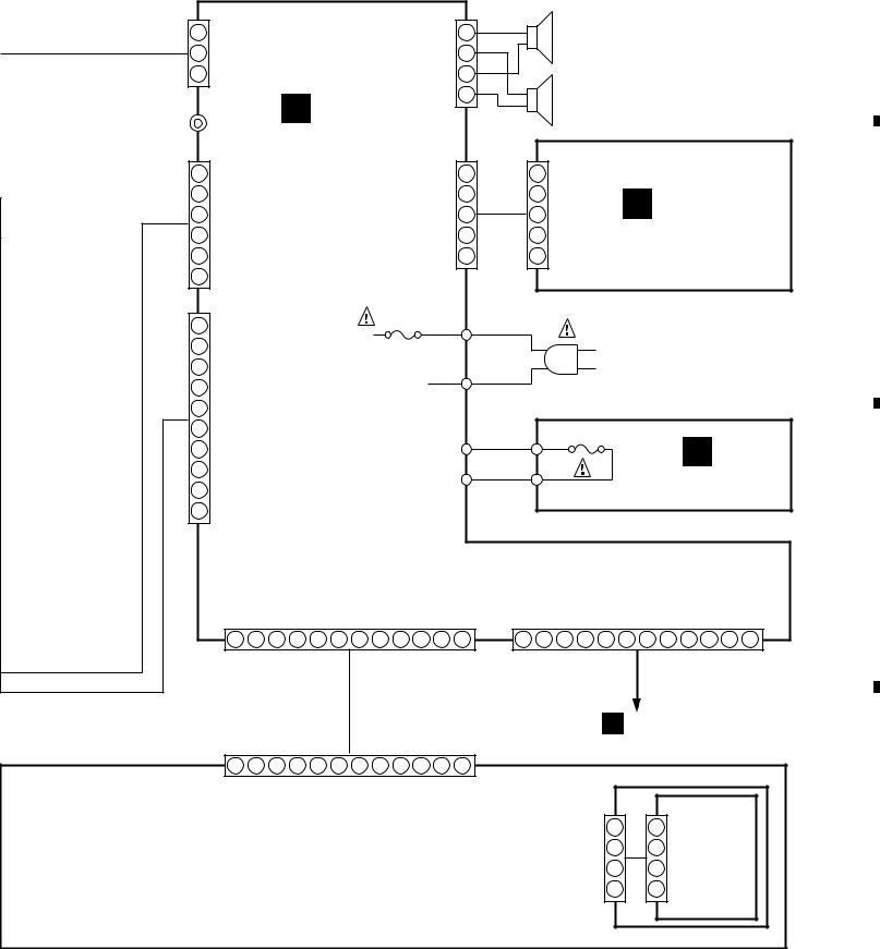
|
5 |
|
6 |
|
7 |
|
8 |
|
|
|
|
|
|
X-HMD01, X-HMD03, X-HX99, X-HX05
Note : When ordering service parts, be sure to refer to "EXPLODED VIEWS and PARTS LIST" or "PCB PARTS LIST".
A
CN306
1NC
2GND
3TX
CD-MD
OUTPUT J303
CN302
1COM+5V
2CDAGND
3CDGGND
4CDM+9V
5CDMGND
6FUNC CD
CN300
1FACOM
2COM+5V
3COM GND
4LEDGND
5LED+9V
6AUGND
7AU+9V
8L ch
9GND
10 R ch
CON |
PCON |
1 |
2 |
CN303
|
J301 |
|
|
|
|
|
LOUT |
1 |
|
L |
|
|
|
|
|
|
|
|
ROUT |
2 |
|
|
|
|
LGND |
3 |
|
SPEAKER SYSTEM |
|
|
|
|
|
||
C |
RGND |
4 |
|
R |
|
|
|
|
|
||
|
|
|
|
|
|
POWER PCB |
|
|
|
|
|
(66789) |
CN304 |
|
|
CN305 |
|
HPGND |
1 |
1 |
HPGND |
|
|
|
|
||||
|
HPROUT |
2 |
2 |
HPROUT |
E |
|
ROUT |
3 |
3 |
ROUT |
|
|
LOUT |
4 |
4 |
LOUT |
HEADPHONE PCB |
|
HPLOUT |
5 |
5 |
HPLOUT |
B |
|
|
|
|
|
|
F302 |
E304 |
LIVE |
|
|
|
|
|
|
|
||
|
|
|
|
AC120V |
|
|
E303 |
|
|
60Hz |
|
|
NEUTRAL |
AC POWER CORD |
|
||
|
|
|
|||
|
|
|
|
||
|
TM3 |
|
TM5 |
F301 |
D |
|
|
5A/125V |
|||
|
|
|
|||
|
|
|
TM6 |
(51604) |
|
|
TM4 |
|
|
FUSE PCB |
|
|
|
|
|
||
|
|
|
|
|
C |
SYSSI |
SYSSO |
SYSCLK |
SUBCS |
SUBREQ |
SUBRST |
B.LED+9V |
B.LEDGND |
COMGND |
COM+5V |
|
|
|
|
|
|
|
|
|
|
|
|
3 |
4 |
5 |
6 |
7 |
8 |
9 |
10 |
11 |
12 |
1 |
2 |
3 |
4 |
5 |
6 |
7 |
8 |
9 |
10 |
11 |
12 |
|
|
|
|
|
|
|
|
|
|
CN301 |
|
|
|
|
|
|
|
|
|
|
|
G CN805
|
1 |
2 |
3 |
4 |
5 |
6 |
7 |
8 |
9 |
10 |
11 |
12 |
|
|
|
|
CN503 |
CON |
PCON |
SYSSI |
SYSSO |
SYSCLK |
SUBCS |
SUBREQ |
SUBRST |
B.LED+9V |
B.LEDGND |
COMGND |
COM+5V |
BLY |
1 |
1 |
D |
|
|
|
|
|
|
|
|
|
|
|
|
|
|
|
|
|
|
|
|
|
|
|
|
|
|
|
|
|
|
CN504 |
|
|
CN505 |
|
|
|
|
|
|
|
|
|
|
|
|
|
BLG |
2 |
2 |
|
|
|
|
|
|
|
|
|
|
|
|
|
|
BL GND |
3 |
3 |
|
|
|
|
|
|
|
|
|
|
|
|
|
|
BL9V |
4 |
4 |
|
17
|
5 |
|
6 |
|
7 |
|
8 |
|
|
|
|
|
|
||||
|
|
|
|
|
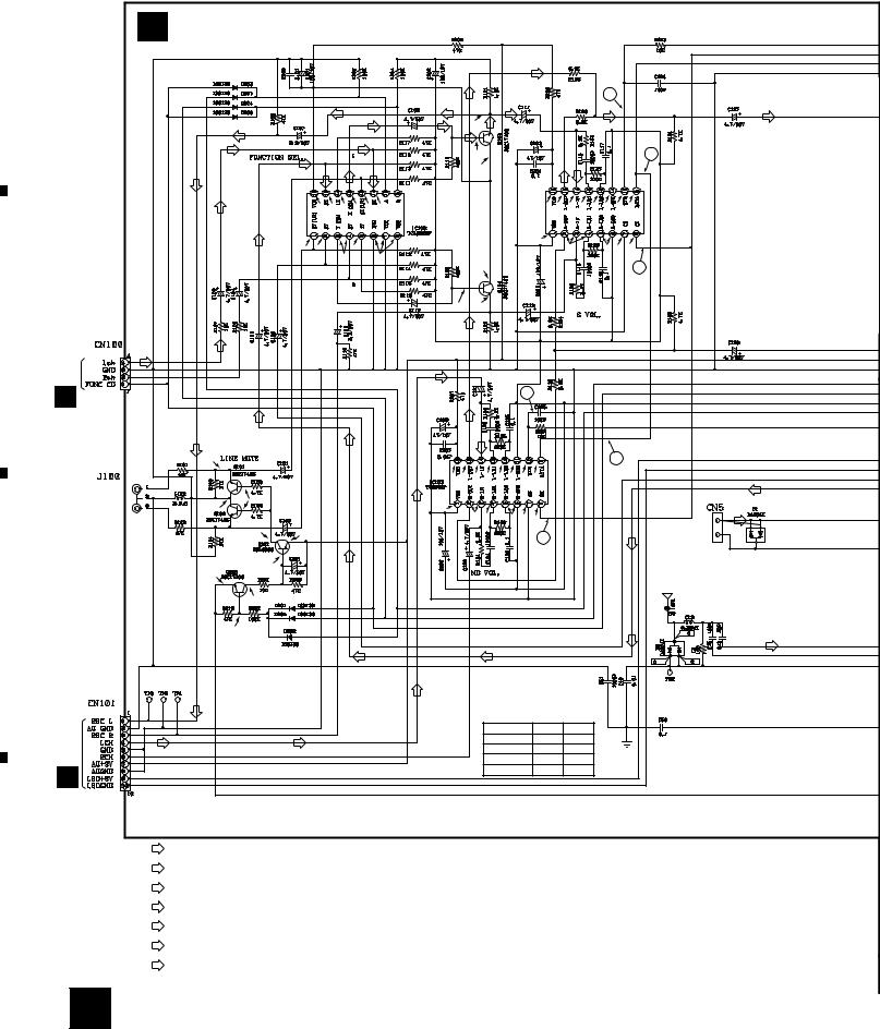
|
1 |
|
2 |
|
3 |
|
4 |
|
|
|
|
|
|
X-HMD01, X-HMD03, X-HX99, X-HX05
3.2.1.2 TUNER PCB |
|
|
|
|
|
|
|
|
|
|
|
|
|
|
|
|
|
|
|
|
|
|
|
|
||
A |
|
A TUNER PCB (66675) |
|
|
|
|
|
|
|
|
|
|
|
|
|
|
|
|
|
|
|
|||||
|
|
|
|
|
|
|
|
|
|
|
|
|
|
|
|
|
|
|
|
|
|
|
|
|
|
|
|
|
|
|
|
|
|
|
|
|
|
|
|
|
|
|
|
(MD) |
|
|
|
|
|
|
|
|
|
|
|
|
|
|
|
|
|
|
|
|
(MD REC) |
(MD) |
|
|
|
|
|
|
|
|
|
6 |
|
|
|
|
|
|
|
|
|
|
|
(MD REC) |
|
|
|
|
|
|
|
|
|
|
|
|
|
|
|||||
|
|
|
|
|
|
|
|
|
|
|
|
|
|
|
|
|
|
|
|
|
|
|||||
|
|
|
|
|
|
|
|
|
|
|
|
|
|
|
|
|
|
|
|
|
|
|
|
|||
|
|
|
(MD REC) |
|
|
|
|
|
|
|
|
2.47V |
|
|
|
|
|
|
|
|
|
|
|
|
|
|
|
|
|
|
|
|
|
|
|
|
|
|
|
|
|
|
|
|
|
|
|
|
|
|
|
|
|
|
|
|
(CD) |
|
|
|
|
(CD) |
|
|
|
|
|
|
|
|
|
|
|
|
|
|
|
|
|
|
|
|
(MDREC) |
|
|
(T) |
|
|
|
(CD) |
|
|
|
3.1V |
|
|
|
|
|
|
|
|
|
|
|
5 |
|
|
|
|
(T) |
|
|
|
|
|
|
7.08V |
|
|
|
|
|
|
|
|
|
|
|
|
||||
|
|
|
|
|
|
|
|
|
|
|
|
|
|
|
|
|
|
|
|
|
|
|
|
|
|
|
|
|
|
|
|
|
|
|
|
|
|
|
|
|
|
|
|
IC101 |
|
|
|
|
|
|
|
|
|
|
|
|
(CD) |
|
7.08V |
3.8V |
3.08V |
3.75V |
3.08V |
3.75V |
|
|
|
|
|
(TC9260P)8.31V |
3.81V |
3.81V |
3.81V |
3.81V |
3.81V |
0V |
4.68V |
|
||
|
|
|
|
|
|
|
|
|
|
|
|
|
|
|
|
|
521889 |
|
|
|
|
|
|
|
|
|
|
|
|
(T) |
|
|
|
3.55V |
|
0V |
|
|
|
|
|
|
|
0V |
|
3.81V |
|
|
3.81V |
0V |
4.8V |
|
|
|
|
|
3.8V |
3.8V |
|
|
|
|
|
|
|
|
|
|
|
|
|
|
||||||||
|
|
|
|
|
|
3.8V |
|
|
|
|
|
|
|
|
|
|
|
|
|
|
|
|
|
|
||
|
|
|
|
|
|
|
|
|
|
|
|
|
7.08V |
|
|
|
|
|
|
|
|
|
|
|
4 |
|
|
|
|
|
|
|
|
|
|
|
|
3.1V |
2.48V |
|
|
|
|
|
|
|
|
|
|
|
|
||
B |
|
|
(CD) |
|
|
|
|
|
|
|
|
(MD) |
|
|
|
|
|
|
|
|
|
|
|
|
|
|
CN404 |
66769 |
(CD) |
|
|
|
|
|
|
|
|
|
|
|
|
|
|
|
|
|
|
|
|
|
|
||
B |
|
|
|
|
|
|
|
|
|
(MD) |
|
|
|
|
|
6 |
|
|
|
|
|
|
|
|
|
|
|
|
|
|
|
|
|
|
|
|
|
|
|
|
|
|
|
|
|
|
|
|
|
|
|
||
|
|
|
|
|
|
|
|
|
|
|
|
|
|
|
|
|
|
|
|
|
|
|
|
|
|
|
|
|
(MD REC) |
(T) |
|
|
|
(T) |
|
|
|
|
(MD) |
(MD) |
|
|
|
|
|
|
|
|
|
|
5 |
|
|
|
|
|
0V |
|
|
|
|
|
|
|
|
|
|
|
|
|
|
|
|
|
|
|
|
|
|
|
|
INPUT L |
|
|
|
|
|
|
|
|
|
8.31V |
3.81V |
3.81V |
3.81V |
3.81V |
3.81V |
0V |
4.68V |
|
|
|
|
|
|
|
(T) |
|
|
0.72V |
|
|
|
|
|
|
(MD) |
|
|
|
|
|
|
|
|
|
|
|
|
|
|
|
|
|
|
(AUX) R |
|
|
|
|
|
|
|
|
|
|
|
|
|
|
|
|
|
|
|
|
|
|
|
||
|
|
0V |
|
|
|
|
|
|
0V |
|
3.81V |
3.81V |
|
3.81V |
|
|
|
|
|
|
|
|
|
(AM) |
||
|
|
|
|
|
|
|
|
|
|
|
|
|
|
0V |
4.8V |
|
|
|
|
|
|
(T) |
||||
|
|
|
8.63V |
8.66V |
|
|
|
|
|
|
|
|
|
|
|
|
|
|
AM LOOP |
|||||||
|
|
|
|
|
|
|
|
|
|
|
|
|
|
|
|
|
|
|
|
|
|
|
|
|
|
|
|
|
|
|
|
|
|
|
|
|
|
|
|
|
|
|
|
|
4 |
|
|
|
|
|
|
|
ANTENNA |
|
|
|
7.95V |
|
|
|
(T) |
|
|
|
|
|
|
|
|
|
|
|
|
|
|
|
|
|
|
FM |
|
|
|
0V |
|
|
|
|
|
|
|
|
|
|
|
|
|
|
|
|
|
|
|
|
|
|
|
|
|
|
|
|
|
|
|
|
|
|
|
|
|
|
|
|
|
|
|
|
|
|
|
|
|
ANTENNA |
|
|
|
0V |
|
|
|
|
|
|
|
|
|
|
|
|
|
|
|
|
|
|
|
|
|
|
|
C |
|
|
|
|
|
|
|
|
|
|
|
|
|
|
|
|
|
|
|
|
|
|
|
|
|
|
|
|
|
0.64V |
|
|
|
|
|
|
|
|
|
|
|
|
|
|
|
|
|
|
|
|
|
(T) |
(FM) |
|
|
|
|
|
|
|
|
|
|
|
|
|
|
|
|
|
|
|
|
|
|
|
|
|
|
|
|
|
|
|
|
|
|
|
|
(T) |
|
|
|
|
(T) |
|
|
|
|
|
|
|
|
|
|
|
|
|
51038 |
(MD REC) |
|
|
|
|
|
|
|
(MD) |
|
|
|
IC100 |
|
|
|
|
|
|
|
|
|
|
|
|
CN806 |
|
|
|
|
|
|
|
|
|
|
|
|
|
|
|
|
|
|
|
|
|
|
|
|||
|
|
|
|
|
|
|
|
|
|
|
|
|
|
|
|
|
|
|
|
|
|
|
|
|||
|
|
|
|
|
|
|
|
|
|
|
|
|
FUNCTION |
Pin 9 |
Pin 10 |
|
|
|
|
|
||||||
|
|
|
|
|
|
|
|
|
|
|
|
|
|
|
|
|
|
|
||||||||
|
|
|
|
|
|
|
|
|
|
|
|
|
|
CD |
|
|
|
7.24V |
7.24V |
|
|
|
|
|
||
|
|
(MD) |
|
(MD) |
|
|
|
|
|
|
|
|
|
MD |
|
|
0V |
|
6.85V |
|
|
|
|
|
||
|
|
|
|
|
|
|
|
|
|
|
|
|
|
TU |
|
|
|
7.14V |
0V |
|
|
|
|
|
||
G |
|
|
|
|
|
|
|
|
|
|
|
|
|
AUX |
|
|
0V |
|
0V |
|
|
|
|
|
||
|
|
|
|
|
|
|
|
|
|
|
|
|
|
|
|
|
|
|
|
|
|
|
|
|
|
|
D
(CD)
(MD)
(MD REC)
(AM)
(FM)
(T)
: AUDIO SIGNAL ROUTE |
IC2 |
|
Voltage |
(V) |
|
|
|
|
|
|
|
|
|
|
|
|
|
|
|
Pin No. |
1 |
2 |
3 |
4 |
5 |
6 |
7 |
8 |
9 |
10 |
11 |
12 |
|
|
|
|
|
: CD AUDIO SIGNAL ROUTE |
AM |
|
2.09 |
4.9 |
0 |
0 |
4.9 |
4.9 |
4.9 |
0.49 |
4.14 |
1.56 |
1.61 |
0 |
|
|
|
|
|
FM |
|
2.08 |
4.82 |
1.01 |
0 |
4.82 |
4.83 |
4.81 |
0.5 |
4.06 |
1.57 |
1.63 |
2.03 |
|
|
|
|
: MD AUDIO SIGNAL ROUTE |
Pin No. |
13 |
14 |
15 |
16 |
17 |
18 |
19 |
20 |
21 |
22 |
23 |
24 |
|
|
|
|
|
|
AM |
|
1.87 |
2.08 |
2.05 |
2.13 |
0 |
4.88 |
4.89 |
2.09 |
2.07 |
2.1 |
2.09 |
1.47 |
|
|
|
|
: MD REC ANALOG AUDIO SIGNAL ROUTE |
FM |
|
2.08 |
2.08 |
2.07 |
2.39 |
0 |
4.83 |
4.83 |
2.09 |
2.65 |
2.09 |
2.09 |
1.53 |
|
|
|
|
: AM SIGNAL ROUTE |
IC3 |
Voltage (V) |
|
|
|
|
|
|
|
|
|
|
|
|
|
|
||
Pin No. |
1 |
2 |
3 |
4 |
5 |
6 |
7 |
8 |
9 |
10 |
11 |
12 |
13 |
14 |
15 |
16 |
||
: FM SIGNAL ROUTE |
AM |
|
2.37 |
1.8 |
0 |
0.28 |
0.19 |
4.89 |
4.87 |
1.87 |
0 |
0 |
2.31 |
0 |
4.85 |
4.85 |
1.16 |
0 |
FM |
|
2.18 |
1.18 |
0 |
0 |
0 |
4.83 |
0.3 |
2.08 |
0 |
0 |
0 |
2.2 |
4.57 |
4.57 |
1.16 |
0 |
|
: TUNER AUDIO SIGNAL ROUTE
18 A
|
1 |
|
2 |
|
3 |
|
4 |
|
|
|
|
|
|
||||
|
|
|
|
|

|
|
|
5 |
|
|
|
|
|
|
|
|
|
|
|
|
|
6 |
|
7 |
|
8 |
|
|
|
|
|
|
|
|
|
|
|
|
|
|
|
|
|
|
X-HMD01, X-HMD03, X-HX99, X-HX05 |
|||
|
|
|
|
|
|
|
|
|
|
|
|
|
|
|
|
|
|
|
|
|
A |
|
|
|
|
|
|
|
|
|
|
|
|
|
|
|
|
|
|
|
51037 |
|
|
|
|
|
|
|
|
|
|
|
|
|
|
|
|
|
|
|
|
|
|
|
F CN502 |
|
|
|
|
|
4.04V |
|
4.05V |
4.06V |
|
|
|
|
3 |
|
2 |
1 |
|
|
1SS133 |
|
|
|
|
|
|
|
|
|
|
|
|
|
|
|
|
|
0V |
|
|
||||
|
|
|
|
|
|
|
|
|
|
|
|
|
|
1.46V |
D208 |
|
|
||||
IC102 |
|
|
|
|
|
|
|
|
|
|
|
|
|
|
|
|
|
|
|
|
|
|
|
|
|
|
|
|
|
|
|
|
|
4.7V |
4.7V |
|
|
|
C214 |
4.7/50 |
|
|
|
52192 |
3.75V |
4.03V |
4.04V |
4.05V |
|
|
4.05V |
|
3.76V |
1.46V |
1.8V |
2.37V |
0V |
3.82V |
0V |
|
|
||||
(BH3854AS) |
|
|
|
|
|
|
|||||||||||||||
|
0V |
4.02V |
4.04V |
4.05V |
4.04V |
4.05V |
4.05V |
4.06V |
3.75V |
7.56V |
3.77V |
0V |
7.73V |
0V |
0V |
0V |
|
|
51039 |
|
|
|
|
|
|
|
|
|
|
|
|
|
|
|
|
|
|
|
|
|
|
|
|
|
|
|
|
|
|
|
|
|
|
|
|
|
|
|
|
|
|
|
|
C CN300 |
|
|
|
|
|
|
|
|
|
|
|
|
|
|
|
|
|
|
|
|
|
|
B |
(T) |
|
|
|
|
|
|
|
|
|
|
|
|
|
|
|
|
|
(T) |
(T) |
|
|
(AM) |
|
|
|
|
|
|
|
|
|
(AM) |
|
|
|
L1 |
|
L2 |
|
(T) |
|
||
|
|
|
|
|
|
|
|
|
|
|
|
|
|
|
|
||||||
|
|
|
|
|
D2 |
|
|
|
|
|
|
|
|
|
50764 |
|
50765 |
57213 |
|
|
|
|
|
|
|
|
|
|
|
|
|
|
|
|
|
|
|
|
|
|
|
||
|
|
|
|
|
57713 |
|
|
|
|
|
|
|
|
|
|
|
|
|
|
||
|
|
|
|
(SVC384) |
|
|
|
|
|
|
|
|
|
|
|
|
|
||||
|
|
|
|
|
|
|
|
|
|
|
|
|
|
57216 |
|
|
|
||||
|
|
|
|
|
|
|
|
|
|
|
|
|
|
|
|
|
|
|
|
|
|
|
|
|
|
|
|
|
|
|
|
|
|
|
|
|
|
|
(AM) |
(AM) |
|
|
|
|
|
|
|
|
|
|
|
|
|
|
|
|
|
|
|
|
|
|
IC2 |
|
C |
|
|
|
|
|
|
|
|
|
|
|
|
|
|
|
|
|
|
|
|
|
|
|
|
|
|
|
|
|
|
|
|
|
|
|
|
|
|
|
|
|
52190 |
|
|
(FM) |
|
|
|
|
|
|
|
|
|
|
|
|
|
|
|
|
|
|
(BA1450S) |
(T) |
|
|
|
|
|
|
|
|
|
|
|
(FM) |
|
|
|
|
|
(FM) |
|
3.97V |
|
|
|
|
|
|
|
|
|
|
|
|
|
|
|
|
|
|
|
|
(T) |
|
|
||
|
|
|
|
|
|
|
|
|
|
|
|
|
|
|
|
|
|
|
|
||
|
|
|
|
|
|
|
|
|
|
|
|
|
|
|
|
|
(FM) |
56514 |
|
|
|
|
|
|
|
|
|
|
|
|
|
|
|
|
|
|
|
0.75V |
|
|
|||
50763 |
|
|
|
|
|
|
|
|
|
|
|
|
|
|
|
(FM) |
|
(FM) |
|
|
|
|
|
|
|
|
|
|
|
|
|
|
|
|
|
|
|
|
0.1V |
|
|
||
|
|
|
|
|
|
|
|
|
|
|
|
|
|
|
|
|
(FM) |
|
|
||
|
|
|
|
|
|
|
|
|
|
|
|
|
|
|
|
|
|
4.92V |
|
|
|
|
|
|
|
|
|
|
|
|
|
|
|
|
|
|
|
|
|
4.76V |
|
|
|
|
|
|
|
|
|
|
|
|
|
|
|
|
|
|
|
|
|
4.09V |
4.88V |
|
4.97V |
|
|
|
|
|
|
|
|
|
|
|
|
|
|
|
|
|
|
50767 |
|
|
|
|
|
|
|
|
|
|
|
|
|
|
|
|
|
|
|
|
|
|
4.21V |
|
|
|
|
|
|
|
|
|
|
|
|
|
|
|
|
|
|
|
|
|
4.21V |
3.68V |
|
|
|
|
|
|
|
|
|
|
|
|
|
|
|
|
|
|
|
|
|
|
|
|
|
|
|
|
|
|
|
|
|
|
|
|
|
|
|
IC3 |
52193 |
|
3.04V |
|
|
|
|
|
|
|
|
|
|
|
|
|
|
|
|
|
|
(BU2614) |
|
|
|
|
|
|
|
|
|
|
|
|
|
|
|
|
|
|
|
|
|
|
|
|
|
|
D |
|
|
|
|
|
|
|
|
|
|
|
|
|
|
|
|
|
|
|
7 |
|
A 19 |
|
|
|
5 |
|
|
|
|
|
|
|
|
|
|
|
|
|
6 |
|
|
8 |
|
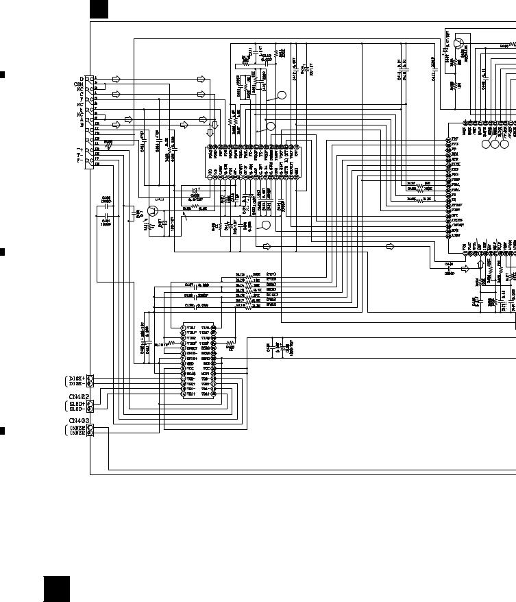
|
1 |
|
2 |
|
3 |
|
4 |
|
|
|
|
|
|
X-HMD01, X-HMD03, X-HX99, X-HX05
3.2.1.3 CD PCB
A
B CD PCB (66786)
C 5
B
CN400
51014
PICKUP ASSY
(CD) |
(CD) |
57216 |
(CD) |
(CD) |
|
2
(CD) |
|
(CD) |
(CD) |
|
|
||
|
(CD) |
|
|
IC400 |
(CD) |
|
|
|
|
|
|
|
|
|
|
|
1 |
|
|
|
|
|
|
(CD) |
|
2.47V |
2.46V |
2.44V |
2.44V |
2.29V |
2.29V |
2.44V |
2.42V |
2.44V |
2.44V |
2.43V |
0.4V |
|
|
2.44V |
2.41V |
||
52103 |
|
2.44V |
1.7V |
0V |
0V |
||||||||||||||
(AN8806SB) |
|
|
|
|
|
|
|
|
|
|
|
|
|
|
|
|
|
|
|
|
0.23V |
3.64V |
4.8V |
0.55V |
4.88V |
2.44V |
2.87V |
2.46V |
3.6V |
1.57V |
3.8V |
3.14V |
3.5V |
0V |
3.51V |
0V |
0V |
0V |
|
1.87V 


4.29V |
3.61V |
3 |
|
||
|
|
(CD) |
2.52V |
2.68V |
4.92V |
4.5V |
0V |
2.6V |
4.85V |
0V |
0V |
0V |
0V |
2.41V |
|
|
|
|
|
|
|
2.44V |
|
|
10 |
9 |
8 |
|
|
0V |
|
|
|
|
|||
|
|
|
|
|
|
|
|
2.4V |
|
|
|
|
|
|
|
2.4V |
|
|
|
|
IC402 |
||
2.4V |
|
|
|
|
|||
2.4V |
|
|
|
|
5218 |
||
2.48V |
|
|
(MN662741 |
||||
2.44V |
|
|
|
|
|
|
|
2.19V |
|
|
|
|
|
|
|
2.6V |
|
|
|
|
|
|
|
2.44V |
|
|
|
|
|
|
|
2.44V |
|
|
|
|
|
|
|
2.41V |
|
|
|
|
|
|
|
0V |
|
|
|
|
|
|
|
0V |
|
|
|
|
|
|
|
0V |
|
|
|
|
|
|
|
2.13V |
|
2.45V |
2.42V |
2.09V |
|
|
|
0V |
|
|
|
|
|||
|
|
|
|
|
|
|
|
2.13V |
|
|
|
|
|
|
|
(CD) |
|
|
|
|
|
|
|
0V |
4.86V |
3.3V |
0V |
2.44V |
4.87V |
4.87V |
0V |
(CD) |
|
|
(CD) |
|
|
|
|
|
|
|
|
|
|
|
|
|
|
|
IC401 |
|
2.4V |
2.41V |
52118 |
|
2.44V |
2.44V |
(BA6299FP) |
C |
2.43V |
2.45V |
|
2.44V |
2.44V |
|
|
|
|
||
|
7.45V |
0V |
|
|
7.45V |
0V |
|
|
0V |
0V |
|
CN401 |
0V |
0V |
|
7.89V |
7.89V |
|
|
SPINDLE 51033 |
2.44V |
7.89V |
|
MOTOR |
0.5V |
0.12V |
|
0V |
0.69V |
|
|
ASSY |
0V |
0.17V |
|
0V |
0.1V |
|
SLED
MOTOR
ASSY
INNER
SW
D
20 B
|
1 |
|
2 |
|
3 |
|
4 |
|
|
|
|
|
|
||||
|
|
|
|
|
|
5 |
|
6 |
|
|
C CN306
CN407
51034
12
5 6 7
2.52V |
2.68V |
4.92V |
4.5V |
0V |
2.6V |
4.85V |
0V |
0V |
0V |
0V |
4.98V |
4.78V |
4.0V |
2.63V |
0V |
4.88V |
2.5V |
2.48V |
2.63V |
|
|
|
|
4.87V |
|
|
10 |
9 |
8 |
0V |
|
|
0V |
|
|||
|
|
|
|
|
|
|
|
|
|
0V |
|
|
|
|
IC402 |
4.87V |
|
|
|
|
2.32V |
|
|
|
|
|
52187 |
0V |
(CD) |
|
(MN662741RHM) |
2.32V |
|||
|
|
|
|
4.56V |
(CD) |
|
|
|
|
4.87V |
|
|
|
|
|
4.87V |
|
|
|
|
|
4.87V |
|
|
|
|
|
4.87V |
|
|
|
|
|
4.97V |
|
|
|
|
|
4.87V |
|
|
|
|
|
4.87V |
|
|
|
|
|
4.87V |
|
2.45V |
2.42V |
2.09V |
|
0V |
|
11 |
4.82V |
|
|||
|
|
|
4.64V |
|
|
0V |
4.86V |
3.3V |
0V |
2.44V |
4.87V |
4.87V |
0V |
2.77V |
2.45V |
2.43V |
0.1V |
4.86V |
0V |
2.4V |
2.45V |
4.87V |
|
) |
|
|
(CD) |
|
|
|
|
|
|
|
|
|
|
X400 |
4 |
||
|
|
|
|
|
|
|
|
|
|
|
|
|
|
60266 |
|
||
|
7 |
|
8 |
|
|
X-HMD01, X-HMD03, X-HX99, X-HX05
(CD)
: CD AUDIO SIGNAL ROUTE
(CD) |
51035 |
CN100 |
|
4.93V |
CABLE HOLDER |
A |
|
51048-0400 |
|
|
|
4.88V 4.22V
4.22V
4.76V
4.1V
CN405
51036  CN302 C

 F CN501
51032
B 21
A
B
C
D
|
5 |
|
6 |
|
7 |
|
8 |
|
|
|
|
|
|
||||
|
|
|
|
|
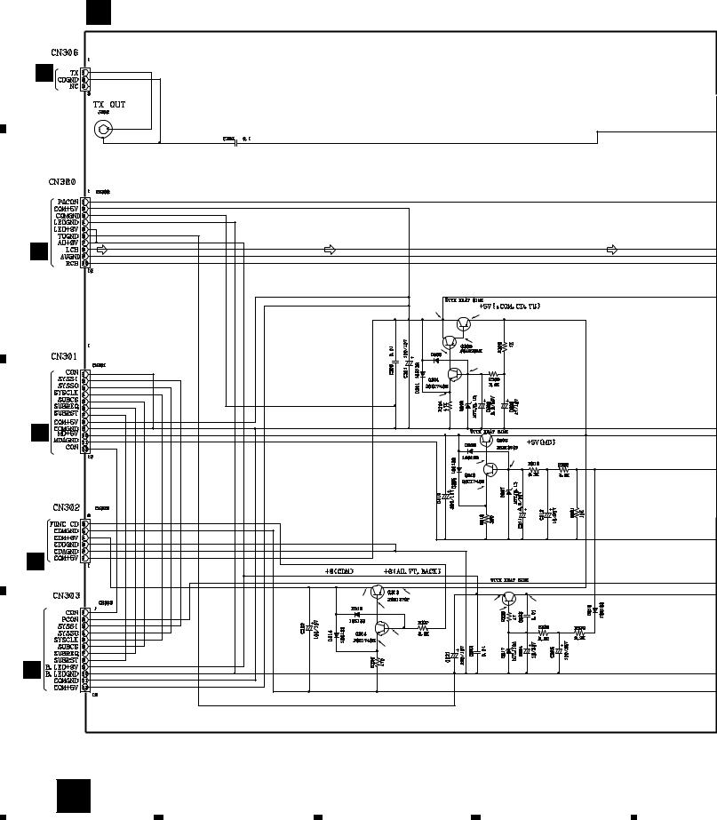
|
1 |
|
2 |
|
3 |
|
4 |
|
|
|
|
|
|
X-HMD01, X-HMD03, X-HX99, X-HX05
3.2.1.4 POWER, FUSE and HEADPHONE PCB
A |
|
|
C POWER PCB |
|
|
|
|
|
|
|
|
|
|
|
|
|
B |
66771 |
|
|
|
|
|
|
|
|
|
|
|
|
|
|
CN407 |
|
|
|
|
|
|
|
CD-MD |
52527 |
|
|
|
|
|
|
|
|
|
|
|
||
|
OUTPUT |
|
|
|
|
|
|
|
|
66777 |
|
|
|
|
|
B |
CN103 |
|
|
|
|
|
|
A |
|
|
|
|
|
|
|
|
|
|
|
|
|
|
|
|
|
|
|
|
5,06V |
17.9V |
|
|
|
|
|
|
|
|
|
|
|
|
|
|
|
Q302 |
|
|
|
|
|
|
|
54610 |
|
|
|
|
|
|
|
(2SB1370F) |
|
|
|
|
|
|
16.5V |
17.27V |
|
|
|
|
|
|
|
|
|
|
|
51040 |
|
|
RB721Q |
4.88V |
|
|
|
|
|
|
|
||
|
G CN805 |
|
|
|
4.39V |
|
|
|
|
|
|
|
|
|
|
|
|
|
|
|
|
4.98V |
|
|
|
|
|
|
|
17.4V |
|
C |
|
|
|
|
|
|
|
|
|
|
|
|
|
4.35V |
|
|
CN405 |
66768 |
|
|
|
|
57212 |
|
|
|
|
|
|
||
|
B |
|
|
|
|
Q315 |
|
|
|
|
|
|
54624 |
|
|
|
|
|
|
|
|
|
|
|
|
|
|
|
|
(2SD2061F) |
|
|
|
51032 |
|
7.88V |
17.9V |
|
|
|
|
|
|
8.67V |
17.9V |
||
|
|
|
|
17.3V |
|||
|
|
|
|
|
9.29V |
|
|
|
|
|
|
|
|
|
|
|
CN503 |
|
|
|
7.73V |
|
|
|
|
|
|
7.16V |
|
|
|
|
|
|
|
|
|
|
|
|
F |
|
|
|
|
|
|
D |
|
|
|
|
|
|
|
|
22 |
C |
|
|
|
|
|
|
|
1 |
2 |
|
3 |
|
4 |

|
5 |
|
6 |
|
7 |
|
8 |
|
|
|
|
|
|
X-HMD01, X-HMD03, X-HX99, X-HX05
A
IC300 |
52115 (BA5412) |
: AUDIO SIGNAL ROUTE |
|
|
|
|
|
|
|
|
|
|
|
|
|
|
60246 |
|
|
|
17.8V |
8.28V |
14.1V |
0.59V |
0V |
0V |
15V |
0V |
0.59V |
14.1V |
8.25V |
0V |
|
L |
|
|
|
|
|
|
|
|
|
|
|
|
|
|
|
|
|
|
|
|
|
|
|
|
|
|
|
|
|
|
|
SPEAKER |
|
|
|
|
|
|
|
|
|
|
|
|
|
|
|
R |
|
|
|
|
|
|
|
|
|
|
|
|
|
|
CN304 |
CN305 |
|
|
|
|
|
|
|
|
|
|
|
|
|
|
66767 |
51041 |
|
|
|
|
|
|
|
|
|
|
|
|
|
|
CABLE HOLDER |
52513 |
B |
|
|
|
|
|
|
|
|
|
|
|
|
|
51052-05000 |
|
|
|
4.65V |
|
|
|
|
17.82V |
|
|
|
|
|
|
PHONES |
|
||
4.65V |
|
|
|
|
|
17.1V |
|
|
|
|
|
|
|
|
|
|
|
|
17.9V |
|
|
|
|
|
|
|
|
E HEADPHONE |
|
||
4.05V |
|
|
|
|
|
|
|
|
|
|
|
|
|
||
|
|
|
|
|
|
|
|
|
|
|
|
|
PCB |
|
|
|
|
|
|
|
|
|
0.66V |
|
0V |
|
|
|
|
|
|
|
|
|
|
|
|
|
|
|
|
|
|
|
|
|
|
|
|
|
|
|
|
|
|
|
0V |
|
|
|
|
|
|
16.6V |
|
|
|
|
|
|
|
|
|
|
|
|
|
|
|
17.3V |
|
|
|
|
|
|
|
|
|
|
|
|
|
|
|
|
|
|
|
|
|
|
|
|
|
|
F302 |
|
|
|
C |
16.52V |
|
|
|
|
|
|
|
|
|
|
|
|
|
|
|
|
|
|
|
|
|
|
|
|
|
750mA/250V |
|
|
|
||
|
|
|
|
|
|
|
|
|
|
|
51607 |
66745 |
LIVE |
|
|
0.64V |
|
|
|
|
|
|
|
|
|
|
|
|
|
|
|
|
|
|
|
|
|
|
|
|
|
|
|
AC120V |
|
|
|
0V |
|
|
|
|
|
|
|
|
|
|
|
|
|
|
|
|
|
|
|
|
|
|
|
|
|
|
|
|
60Hz |
|
|
|
|
|
|
|
|
|
|
|
|
|
|
66745 |
NEUTRAL |
|
|
0V |
|
|
|
|
|
|
|
|
|
|
|
AC POWER CORD |
|
|
|
|
|
|
|
|
|
|
|
|
|
|
|
50319 : KBW |
|
|
|
|
|
|
|
|
|
|
|
|
|
|
F301 |
|
|
|
|
|
|
|
|
|
|
|
|
|
|
|
51604 |
|
|
|
|
|
|
|
|
|
|
|
|
|
|
|
5A/125V |
|
|
|
|
|
|
|
|
|
|
|
|
|
|
|
D FUSE PCB |
|
|
|
|
|
|
|
|
|
|
|
|
|
|
|
|
|
|
|
D |
|
|
|
|
|
|
|
|
|
|
|
7 |
|
C D E 23 |
|
|
5 |
|
|
|
|
|
6 |
|
|
|
|
8 |
|
|
||
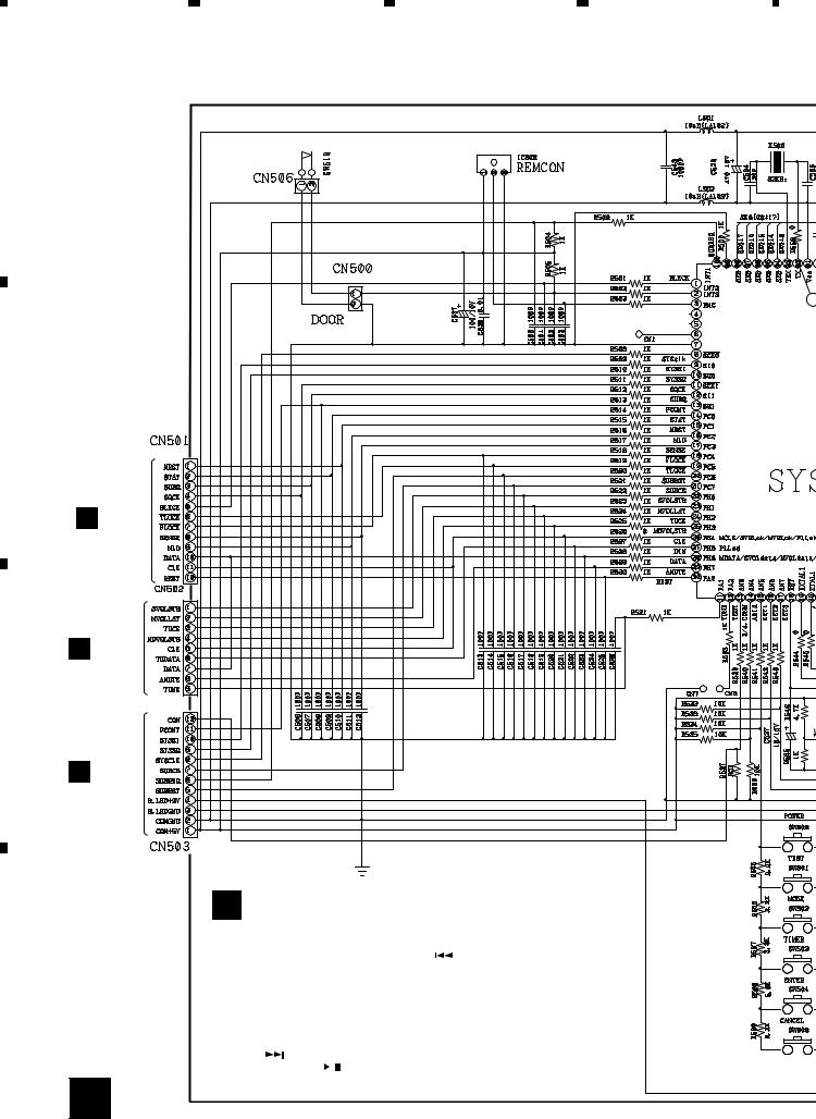
1 |
2 |
3 |
4 |
X-HMD01, X-HMD03, X-HX99, X-HX05 |
|
|
|
3.2.1.5 FRONT CD PCB |
|
|
|
A |
DOOR SW |
|
60245 |
|
|
||
|
|
|
56560 |
|
66772 |
|
|
51032
3
IC501 52206
(CXP832
B
66765
B CN406
66766
A CN102
C
57213 |
0.6 |
|
C CN303
53426
66764
F FRONT CD PCB (66788)
|
FRONT CD PCB |
|
|||
|
SW500 : POWER STANDBY/ON |
SW510 : - ( ) |
|||
|
SW501 : TIMER SETTING |
SW511 : SLEEP |
|||
D |
SW502 : MODE |
SW512 : VOL- |
|||
SW503 : TIMER |
SW513 : EQ MODE |
||||
|
|||||
|
SW504 : ENTER (MEMORY) |
SW514 : MUSIC UP |
|||
|
SW505 : CANCEL (DELETE) |
SW515 : VOL+ |
|||
|
SW506 : STOP ( |
|
) |
SW516 : SOUND SCAPE UP |
|
|
|
||||
|
|
||||
|
SW507 : SOURCE |
SW517 : P.BASS |
|||
|
SW508 : + ( ) |
SW518 : DISPLAY (MONO) |
|||
|
SW509 : PLAY PAUSE ( ) |
|
|||
24 F
|
1 |
|
2 |
|
3 |
|
4 |
|
|
|
|
|
|
||||
|
|
|
|
|
 Loading...