


W2-2001
auto synchro egiting system |
full logic aut reverse |
stereo double cassette deck |
ORDER NO.
RRV2364
STEREO CD/VCD CASSETTE DECK RECEIVER
XR-VS90SW
XR-VS90 XR-VS70SW XR-VS70
THIS MANUAL IS APPLICABLE TO THE FOLLOWING MODEL(S) AND TYPE(S).
Type |
|
Model |
|
Power Requirement |
The voltage can be converted |
||
XR-VS90SW |
XR-VS90 |
XR-VS70SW |
XR-VS70 |
by the following method. |
|||
|
|
||||||
DBDXJ |
à |
– |
à |
– |
AC110-127V/220-230V/240V |
With the voltage selector |
|
DLXJ/NC |
– |
à |
– |
à |
AC110-127V/220-230V/240V |
With the voltage selector |
|
DXJN/NC |
– |
à |
– |
à |
AC110-127V/220-230V/240V |
With the voltage selector |
|
CONTENTS
1. SAFETY INFORMATION ...................................... |
|
2 |
7. GENERAL INFORMATION |
................................ |
74 |
||||||
|
|
|
|||||||||
2. EXPLODED VIEWS AND PARTS LIST ................ |
|
3 |
7.1 DIAGNOSIS |
................................................. |
74 |
||||||
|
|
|
|
|
|
||||||
3. BLOCKDIAGRAM AND SCHEMATIC DIAGRAM |
.... |
22 |
7.1.1 DISASSEMBLY |
..................................... |
74 |
||||||
|
|
|
|
||||||||
4. PCB CONNECTION DIAGRAM .......................... |
|
42 |
7.2 PARTS |
......................................................... |
77 |
||||||
|
|
|
|
|
|
|
|||||
5. PCB PARTS LIST ............................................... |
|
56 |
7.2.1 IC |
........................................................... |
77 |
||||||
|
|
|
|
|
|
|
|
||||
6. ADJUSTMENT .................................................... |
|
64 |
7.2.2 DISPLAY |
................................................ |
79 |
||||||
|
|
|
|
|
|||||||
|
|
|
8. PANEL FACILITIES AND SPECIFICATIONS |
.... |
81 |
||||||
|
|
|
|
||||||||
PIONEER CORPORATION 4-1, Meguro 1-chome, Meguro-ku, Tokyo 153-8654, Japan PIONEER ELECTRONICS SERVICE, INC. P.O. Box 1760, Long Beach, CA 90801-1760, U.S.A. PIONEER EUROPE NV Haven 1087, Keetberglaan 1, 9120 Melsele, Belgium
PIONEER ELECTRONICS ASIACENTRE PTE. LTD. 253 Alexandra Road, #04-01, Singapore 159936 c PIONEER CORPORATION 2000
T – IZK AUG. 2000 Printed in Japan
XR-VS90SW, XR-VS90, XR-VS70SW, XR-VS70
1. SAFETY INFORMATION
This service manual is intended for qualified service technicians ; it is not meant for the casual do-it- yourselfer. Qualified technicians have the necessary test equipment and tools, and have been trained to properly and safely repair complex products such as those covered by this manual.
Improperly performed repairs can adversely affect the safety and reliability of the product and may void the warranty. If you are not qualified to perform the repair of this product properly and safely, you should not risk trying to do so and refer the repair to a qualified service technician.
WARNING !
THE AEL (ACCESSIBLE EMISSION LEVEL) OF THE LASER POWER OUTPUT IS LESS THAN CLASS 1 BUT THE LASER COMPONENT IS CAPABLE OF EMITTING RADIATION EXCEEDING THE LIMIT FOR CLASS 1.
A SPECIALLY INSTRUCTED PERSON SHOULD DO SERVICING OPERATION OF THE APPARATUS.
LASER DIODE CHARACTERISTICS
MAXIMUM OUTPUT POWER: 5 mW WAVELENGTH: 780 nm to 785 nm
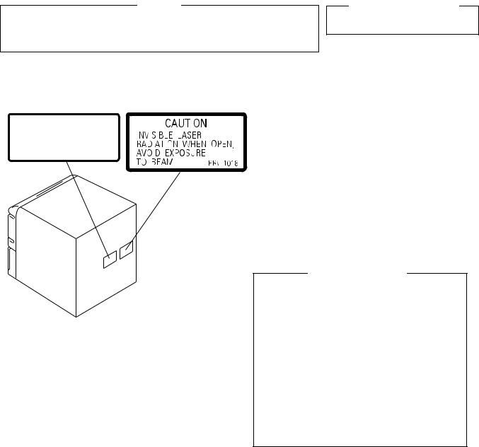
LABEL CHECK (For DLXJ/NC Type)
Printed on the Rear Panel |
DLXJ/NC Type |
|||||||
|
|
|
|
|
|
|
|
|
|
|
|
|
|
|
|
|
|
|
|
|
|
|
|
|
|
|
|
|
|
|
|
|
|
|
|
|
|
|
|
|
|
|
|
|
|
|
|
|
|
|
|
|
|
|
|
|
|
|
|
|
|
|
|
|
|
|
|
|
|
|
|
|
|
|
|
|
|
|
|
|
Additional Laser Caution
1. Laser Interlock Mechanism
The position of the switch (S9501) for detecting loading state is detected by the system microprocessor, and the design prevents laser diode oscillation when the switch (S9501) is pressed physically.
Thus, the interlock will no longer function if the switch (S9501) is released physically and deliberatery.
The interlock also does not function in the test mode . Laser diode oscillation will continue, if pin 62 of LA9240ML (IC1101) on the $M SERVO VCD Assy mounted on the $M MECHANISM VCD is connected to GND, or else the terminals of Q1101 are shorted to each other (fault condition).
2. When the cover is opened, close viewing of the objective lens with the naked eye will cause exposure to a Class 1 laser beam.
: Refer to page 73.
2
XR-VS90SW, XR-VS90, XR-VS70SW, XR-VS70
2. EXPLODED VIEWS AND PARTS LIST
NOTES: ∙ Parts marked by "NSP" and can not be supplied.
∙The  mark found on some component parts indicates the importance of the safety factor of the part.
Therefore, when replacing, be sure to use parts of identical designation.
∙Screws adjacent to  mark on the product are used for disassembly.
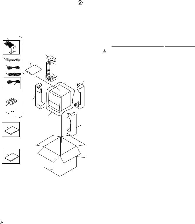
2.1PACKING
4 |
(1) PACKING PARTS LIST |
|
|||
|
Mark |
No. |
Description |
Part No. |
|
5 |
9(1/2) |
1 |
Power Cord |
See Contrast table (2) |
|
1 |
|
2 |
FM Antenna |
ADH7004 |
|
11 |
3 |
AM Loop Antenna |
XTB3001 |
||
|
4 |
Remote Control Unit |
XZN3107 |
||
2 |
|
||||
|
5 |
Battery Cover |
XZN3104 |
||
15 |
NSP |
6 |
Dry Cell Battery (R6P, AA) |
VEM-013 |
|
|
|
7 |
Packing Sheet |
AHG7053 |
|
|
9(2/2) |
8 |
Front Pad |
XHA3018 |
|
14 |
|
9 |
Rear Pad |
XHA3019 |
|
|
10 |
Packing Case |
See Contrast table (2) |
||
XR-VS90SW |
NSP |
11 |
Polyethylene Bag |
Z21-038 |
|
only |
|||||
|
|
(0.03 × 230 × 340) |
|
||
|
|
|
|
||
|
8(1/2) |
12 |
Operating Instructions |
See Contrast table (2) |
|
3 |
|
|
(English/Chinese/Spanish) |
|
|
|
13 |
Operating Instructions (Thai) |
See Contrast table (2) |
||
|
|
||||
6 |
|
14 |
AM wire Antenna |
See Contrast table (2) |
|
|
7 |
||||
|
15 |
Video Cord (L=1.5m/Yellow) |
VDE1034 |
||
12 |
8(2/2) |
DBDXJ and |
|
DLXJ/NC types |
|
only |
|
13 |
|
|
10 |
DXJN/NC type |
|
only |
|
(2) CONTRAST TABLE
XR-VS90SW/DBDXJ, XR-VS90/DLXJ/NC, DXJN/NC, XR-VS70SW/DBDXJ, XR-VS70/DLXJ/NC and DXJN/NC are constructed the same except for the following :
|
|
|
|
|
Part No. |
|
|
|
|
Mark |
No. |
Symbol and Description |
|
|
|
|
|
|
Remarks |
XR-VS90SW |
XR-VS90 |
XR-VS70SW |
XR-VS70 |
||||||
|
|
|
|
|
|
|
|
|
|
|
|
|
/DBDXJ |
/DLXJ/NC |
/DXJN/NC |
/DBDXJ |
/DLXJ/NC |
/DXJN/NC |
|
|
1 |
Power Cord |
ADG1158 |
ADG1154 |
ADG1154 |
ADG1158 |
ADG1154 |
ADG1154 |
|
|
10 |
Packing Case |
XHD3132 |
XHD3133 |
XHD3134 |
XHD3124 |
XHD3125 |
XHD3126 |
|
|
12 |
Operating Instructions |
XRE3034 |
XRE3034 |
Not used |
XRE3034 |
XRE3034 |
Not used |
|
|
|
(English/Chinese/Spanish) |
|
|
|
|
|
|
|
|
13 |
Operating Instructions (Thai) |
Not used |
Not used |
XRC3024 |
Not used |
Not used |
XRC3024 |
|
|
14 |
AM wire Antenna |
AHD7006 |
Not used |
Not used |
AHD7006 |
Not used |
Not used |
|
|
|
|
|
|
|
|
|
|
|
3
XR-VS90SW, XR-VS90, XR-VS70SW, XR-VS70
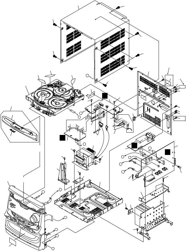
2.2 EXTERIOR SECTION
28
46
45
46
46
46
|
32 (2/3) |
|
|
|
32 (1/3) |
|
32 (3/3) |
G |
|
Refer to |
|
|
|
|
|
|
|
|
|
"2.4 $M MECHANISM VCD". |
|
|
|
|
5 |
|
|
44 |
|
|
|
|
|
|
26 |
|
|
39 |
|
|
|
|
|
|
11 |
|
|
A |
|
|
|
E |
|
|
|
|
33 35 |
12 |
|
|
XR-VS90SW, |
34 |
|
|
|
XR-VS90 |
|
13 |
|
|
only |
|
|
|
27 |
G |
2 |
|
|
Note : |
|
F |
7 |
|
|
41 |
|||
Hook Tray cap on top of loading |
|
|
|
|
tray and then insert the bottom |
|
|
|
|
three hooks. |
39 |
|
|
|
|
25 |
39 |
|
|
|
|
|
|
|
Refer to |
|
|
37 |
|
|
|
|
|
|
"2.3 FRONT PANEL SECTION". |
|
|
|
|
A |
H |
|
|
|
|
|
|
|
|
|
|
|
|
DLXJ/NC type |
|
|
|
|
45 |
only |
|
|
|
|
|
15 |
XR-VS90SW, |
|
|
|
|
46 |
|
|
|
|
|
XR-VS90 |
|
|
|
|
|
31 |
|
46 |
|
|
|
only |
|
|
|
|
|
45 |
|
|
|
|
|
|
|
|
|
|
|
|
45 |
H 3 |
|
|
|
|
45 |
|
39 |
|
|
|
|
|
|
|
|
|
45 |
|
|
|
22 |
|
45 |
|
|
29 |
|
|
45 |
9 |
|
|
|
45 |
|
|
39 |
|
|||
|
|
|
XR-VS90SW, |
||
|
|
|
|
|
|
|
|
|
|
|
XR-VS90 |
|
|
|
|
|
only |
|
16 |
XR-VS90SW, |
|
|
|
8 |
XR-VS90 |
|
|
|
|
|
|
|
|
||
|
|
only |
|
|
|
|
|
4 |
A |
F |
1 |
|
|
E |
|
||
|
|
|
F |
|
|
41 |
|
|
|
|
|
|
H |
B |
|
|
|
|
|
|
|
||
|
|
C |
|
|
|
|
|
D |
|
|
23 |
|
|
|
|
40 |
|
14 |
|
40 |
|
|
|
|
|
|
19 |
|
|
|
|
39 38 |
18 |
|
|
|
|
|
|
|
|
B
C |
39 |
D
36
G
4

XR-VS90SW, XR-VS90, XR-VS70SW, XR-VS70
(1) EXTERIOR SECTION PARTS LIST
Mark |
No. |
Description |
|
Part No. |
|
Mark |
No. |
Description |
|
Part No. |
|
1 |
AF Assy |
|
See Contrast table (2) |
NSP |
26 |
Tray Cap Assy |
|
XXG3046 |
|
|
2 |
SECONDARY Assy |
|
See Contrast table (2) |
|
27 |
Pioneer Badge |
|
XAM3001 |
|
|
3 |
PRIMARY Assy |
|
XWZ3291 |
|
28 |
Bonnet Case |
|
XZN3098 |
|
|
4 |
FM/AM TUNER Module |
|
See Contrast table (2) |
NSP |
29 |
Fuse Card |
|
See Contrast table (2) |
|
NSP |
5 |
$M MECHANISM VCD |
|
See Contrast table (2) |
|
30 |
• • • • • |
|
|
|
|
6 |
• • • • • |
|
|
|
|
31 |
Caution Label |
|
See Contrast table (2) |
|
7 |
Power Transformer (T1) |
|
See Contrast table (2) |
|
32 |
Disc Label |
|
XAX3127 |
|
|
8 |
Fuse (FU2, FU3) |
|
See Contrast table (2) |
|
33 |
ICP Label |
|
See Contrast table (2) |
|
|
9 |
Fuse (FU1) |
|
See Contrast table (2) |
|
34 |
ICP Label |
|
See Contrast table (2) |
|
|
10 |
Spacer |
|
XEC3014 |
|
35 |
ICP Label |
|
See Contrast table (2) |
|
|
11 |
Tray Cap S |
|
XAK3156 |
NSP |
36 |
Getter |
|
See Contrast table (2) |
|
|
12 |
Fuse Card |
|
See Contrast table (2) |
NSP |
37 |
DO NOT THROW Assy |
|
• • • • • |
|
|
13 |
PCB Bracket |
|
ANG7263 |
NSP |
38 |
CABLE HOLDER Assy |
|
• • • • • |
|
NSP |
14 |
Chassis |
|
XNA3006 |
|
39 |
Screw |
|
BBZ30P080FMC |
|
|
15 |
Rear Panel |
|
See Contrast table (2) |
|
40 |
Screw |
|
BBZ30P180FMC |
|
|
16 |
PCB Bracket |
|
XNG3006 |
|
41 |
Screw |
|
ASZ40P060FMC |
|
|
17 |
Binder |
|
ZCA-SKB90BK |
|
42 |
Screw |
|
BPZ30P080FMC |
|
|
18 |
Heat Sink |
|
See Contrast table (2) |
|
43 |
Screw |
|
VBZ30P080FZK |
|
|
19 |
Sub Heat Sink B |
|
XNH3012 |
|
44 |
Barier |
|
XEC3013 |
|
|
20 |
• • • • • |
|
|
|
|
45 |
Screw |
|
BPZ30P100FZK |
|
21 |
• • • • • |
|
|
|
|
46 |
Screw |
|
VBT30P080FZK |
|
22 |
Wire Clip A |
|
XEC3003 |
|
|
|
|
|
|
|
23 |
Card Spacer |
|
XEC3008 |
|
|
|
|
|
|
|
24 |
• • • • • |
|
|
|
|
|
|
|
|
|
25 |
SEC Holder A |
|
See Contrast table (2) |
|
|
|
|
|
|
(2) CONTRAST TABLE
XR-VS90SW/DBDXJ, XR-VS90/DLXJ/NC, DXJN/NC, XR-VS70SW/DBDXJ, XR-VS70/DLXJ/NC and DXJN/NC are constructed the same except for the following :
|
|
|
|
|
Part No. |
|
|
|
|
Mark |
No. |
Symbol and Description |
|
|
|
|
|
|
Remarks |
XR-VS90SW |
XR-VS90 |
XR-VS70SW |
XR-VS70 |
||||||
|
|
|
|
|
|
|
|
|
|
|
|
|
/DBDXJ |
/DLXJ/NC |
/DXJN/NC |
/DBDXJ |
/DLXJ/NC |
/DXJN/NC |
|
Ä |
1 |
AF Assy |
XWZ3313 |
XWZ3313 |
XWZ3313 |
XWZ3300 |
XWZ3300 |
XWZ3300 |
|
|
2 |
SECONDARY Assy |
XWZ3304 |
XWZ3304 |
XWZ3304 |
XWZ3289 |
XWZ3289 |
XWZ3289 |
|
|
4 |
FM/AM TUNER Module |
AXQ7062 |
AXQ7065 |
AXQ7065 |
AXQ7062 |
AXQ7065 |
AXQ7065 |
|
NSP |
5 |
$M MECHANISM VCD |
XXA3017 |
XXA3017 |
XXA3017 |
XXA3016 |
XXA3016 |
XXA3016 |
|
|
7 |
Power Transformer (T1) |
XTS3037 |
XTS3037 |
XTS3037 |
XTS3036 |
XTS3036 |
XTS3036 |
|
|
8 |
Fuse (FU2, FU3) |
AEK1059 |
AEK1059 |
AEK1059 |
AEK1057 |
AEK1057 |
AEK1057 |
|
|
|
|
(T3.15A) |
(T3.15A) |
(T3.15A) |
(T2A) |
(T2A) |
(T2A) |
|
|
9 |
Fuse (FU1) |
AEK1061 |
AEK1061 |
AEK1061 |
AEK1060 |
AEK1060 |
AEK1060 |
|
|
|
|
(T5A) |
(T5A) |
(T5A) |
(T4A) |
(T4A) |
(T4A) |
|
|
12 |
Fuse Card |
AAX7493 |
AAX7493 |
AAX7493 |
Not used |
Not used |
Not used |
|
|
15 |
Rear Panel |
XNC3062 |
XNC3062 |
XNC3062 |
XNC3057 |
XNC3057 |
XNC3057 |
|
|
18 |
Heat Sink |
XNH3010 |
XNH3010 |
XNH3010 |
XNH3009 |
XNH3009 |
XNH3009 |
|
|
25 |
SEC Holder A |
XMR3033 |
XMR3033 |
XMR3033 |
XMR3034 |
XMR3034 |
XMR3034 |
|
NSP |
29 |
Fuse Card |
AAX7098 |
AAX7098 |
AAX7098 |
Not used |
Not used |
Not used |
|
|
31 |
Caution Label |
Not used |
PRW1018 |
Not used |
Not used |
PRW1018 |
Not used |
|
|
33 |
ICP Label |
XAX3121 |
XAX3121 |
XAX3121 |
Not used |
Not used |
Not used |
|
|
34 |
ICP Label |
XAX3153 |
XAX3153 |
XAX3153 |
Not used |
Not used |
Not used |
|
|
35 |
ICP Label |
XAX3158 |
XAX3158 |
XAX3158 |
Not used |
Not used |
Not used |
|
NSP |
36 |
Getter |
XAX3173 |
XAX3173 |
XAX3173 |
XAX3168 |
XAX3168 |
XAX3168 |
|
|
|
|
|
|
|
|
|
|
|
5
XR-VS90SW, XR-VS90, XR-VS70SW, XR-VS70
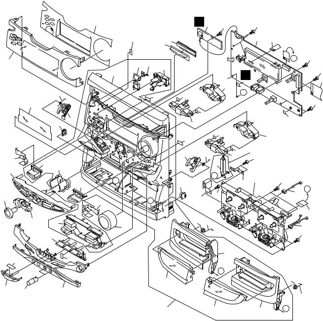
2.3 FRONT PANEL SECTION
|
|
26 |
|
|
|
J 2 |
|
|
52 |
|
2930 |
|
|
|
|
|
|
|
|
|
33 |
|
36 |
43 |
37 |
|
|
|
|
|
|
|||
|
|
|
|
|
|
|
|
|
49 |
|
|
|
|
|
9 |
|
|
59 |
61 |
|
|
|
|
|
|
||
32 |
|
|
|
|
|
|
|
|
|
|
|
|
61 |
|
11 |
16 |
|
|
|
21 |
|
|
|
|
|
||
|
|
|
|
|
59 |
|
34 |
|
|
|
|
17 |
10 |
|
|
|
|
|
||
39 |
|
|
|
|
|
|
|
|
|
|
|
|
|
27 |
46 |
|
|
|
|
|
|
|
|
|
|
|
|
|
|
A |
|
|
11 |
|
|
|
40 |
|
|
|
|
19 |
|
35 |
B |
|
|
7 |
|
|
|
|
|||
|
|
|
|
|
|
|
28 |
38 |
18 |
|
|
|
12 |
|
|
|
|
|
|
|
|
41 |
|
|
|
|
|
53 |
|
52 |
|
|
|
|
|
|
|
|
|
|
|
|
|
|
|
44 |
|
|
55 |
|
55 |
|
|
|
|
1 |
6 |
|
|
|
|
D |
55 |
|
I |
|
|
55 |
|
|
|
4 |
|
23 |
|
|
|
|
60 |
|
|
|
|
|
C |
|
|
|
|
|
|
|
55 |
|
|
|
60 |
|
61 |
|
|
24 |
|
|
|
|
|
|
|
61 |
XR-VS90SW, XR-VS90 only |
||
|
22 |
55 |
|
|
8 |
|
|
|
|
|
Refer to |
|
||
|
|
|
||
C |
|
"2.6 DECK MECHANISM UNIT". |
||
|
3 |
55 |
|
|
|
51 |
|
||
|
|
|
||
|
|
|
D |
|
55 |
|
|
56 |
|
|
|
|
|
|
|
|
|
|
5 |
|
|
|
|
57 |
|
|
|
55 |
|
47
A
25 |
20 |
42 |
|
13
50 |
45 |
48 |
B |
6

XR-VS90SW, XR-VS90, XR-VS70SW, XR-VS70
(1) FRONT PANEL SECTION PARTS LIST
Mark No. |
Description |
|
Part No. |
Mark |
No. |
Description |
|
Part No. |
||
|
1 |
DISPLAY Assy |
|
See Contrast table (2) |
|
|
30 |
LT Conductor S |
|
XAK3155 |
2 |
BLUE LED Assy |
|
XWZ3292 |
|
31 |
• • • • • |
|
|
||
3 |
Deck Mechanism Unit |
|
See Contrast table (2) |
|
32 |
FL Filter |
|
XAK3162 |
||
4 |
Flexible Cable 27P |
|
XDD3041 |
|
33 |
FL Cover |
|
XAK3163 |
||
5 |
Flexible Cable 15P |
|
See Contrast table (2) |
|
34 |
Cover Sheet L |
|
XAK3184 |
||
5 |
Flexible Cable 13P |
|
See Contrast table (2) |
|
35 |
Cover Sheet R |
|
XAK3185 |
||
6 |
Flexible Cable 05P |
|
XDD3042 |
|
36 |
Power Button |
|
XAD3043 |
||
7 |
GND Plate B |
|
XNG3031 |
|
37 |
CD Button |
|
XAD3045 |
||
8 |
GND Plate C |
|
See Contrast table (2) |
|
38 |
SC Button |
|
XAD3060 |
||
9 |
Ratch Spring_L |
|
ABH7130 |
|
39 |
SC Button L |
|
XAD3047 |
||
10 |
Ratch Spring_R |
|
ABH7131 |
|
40 |
SC Button R |
|
XAD3049 |
||
11 |
Damper Assy |
|
XXA3025 |
|
41 |
DOLBY Button |
|
XAD3054 |
||
12 |
Door Spring_L |
|
XBH3010 |
|
42 |
Sub Panel S |
|
See Contrast table (2) |
||
13 |
Door Spring_R |
|
XBH3011 |
|
43 |
ST Lens S |
|
XAK3151 |
||
14 |
• • • • • |
|
|
|
|
44 |
Deck Lens L S |
|
XAK3159 |
|
15 |
• • • • • |
|
|
|
|
45 |
Deck Lens R S |
|
XAK3160 |
|
16 |
Ratch Mold_L |
|
XMR3001 |
|
46 |
JOG Conductor |
|
XAK3165 |
||
17 |
Ratch Mold_R |
|
XMR3002 |
|
47 |
Deck Door_L |
|
See Contrast table (2) |
||
18 |
Volume Knob |
|
XAA3013 |
|
48 |
Deck Door_R |
|
See Contrast table (2) |
||
19 |
JOG Knob |
|
XAA3015 |
|
49 |
Front Panel |
|
XMB3026 |
||
20 |
MIC Knob |
|
XAB3007 |
NSP |
50 |
Front Panel Assy |
|
See Contrast table (2) |
||
21 |
FUNC Button L |
|
See Contrast table (2) |
|
51 |
GND Plate A |
|
See Contrast table (2) |
||
22 |
FUNC Button R |
|
See Contrast table (2) |
|
52 |
Spacer |
|
XEB3012 |
||
23 |
FUNC Frame L |
|
XAD3052 |
|
53 |
Spacer |
|
XEB3013 |
||
24 |
FUNC Frame R |
|
XAD3053 |
|
54 |
• • • • • |
|
|
||
25 |
CD ENT Button |
|
XAD3055 |
|
55 |
Screw |
|
BPZ30P080FMC |
||
26 |
Display Panel |
|
See Contrast table (2) |
|
56 |
Connector Assy 3P |
|
See Contrast table (2) |
||
27 |
EQ Panel S |
|
See Contrast table (2) |
|
57 |
Connector Assy 5P |
|
XDE3038 |
||
28 |
JOG Lens S |
|
XAK3152 |
|
58 |
• • • • • |
|
|
||
29 |
V Lens S |
|
XAK3153 |
|
59 |
Cushion Spacer |
|
XEB3015 |
||
|
|
|
|
|
|
|
60 |
Cushion Spacer |
|
XEB3016 |
|
|
|
|
|
|
|
61 |
Cushion Spacer |
|
XEB3017 |
(2) CONTRAST TABLE
XR-VS90SW/DBDXJ, XR-VS90/DLXJ/NC, DXJN/NC, XR-VS70SW/DBDXJ, XR-VS70/DLXJ/NC and DXJN/NC are constructed the same except for the following :
|
|
|
|
|
Part No. |
|
|
|
|
Mark |
No. |
Symbol and Description |
|
|
|
|
|
|
Remarks |
XR-VS90SW |
XR-VS90 |
XR-VS70SW |
XR-VS70 |
||||||
|
|
|
|
|
|
|
|
|
|
|
|
|
/DBDXJ |
/DLXJ/NC |
/DXJN/NC |
/DBDXJ |
/DLXJ/NC |
/DXJN/NC |
|
Ä |
1 |
DISPLAY Assy |
XWZ3315 |
XWZ3314 |
XWZ3314 |
XWZ3302 |
XWZ3301 |
XWZ3301 |
|
|
3 |
Deck Mechanism Unit |
XYM3012 |
XYM3012 |
XYM3012 |
XYM3011 |
XYM3011 |
XYM3011 |
|
|
5 |
Flexible Cable 15P |
XDD3050 |
XDD3050 |
XDD3050 |
Not used |
Not used |
Not used |
|
|
5 |
Flexible Cable 13P |
Not used |
Not used |
Not used |
XDD3040 |
XDD3040 |
XDD3040 |
|
|
8 |
GND Plate C |
XNG3047 |
XNG3047 |
XNG3047 |
Not used |
Not used |
Not used |
|
|
21 |
FUNC Button L |
XAD3050 |
XAD3050 |
XAD3050 |
XAD3078 |
XAD3078 |
XAD3078 |
|
|
22 |
FUNC Button R |
XAD3051 |
XAD3051 |
XAD3051 |
XAD3079 |
XAD3079 |
XAD3079 |
|
|
26 |
Display Panel |
XAK3133 |
XAK3133 |
XAK3133 |
XAK3129 |
XAK3129 |
XAK3129 |
|
|
27 |
EQ Panel S |
XAK3150 |
XAK3150 |
XAK3150 |
XAK3149 |
XAK3149 |
XAK3149 |
|
|
42 |
Sub Panel S |
XAK3145 |
XAK3145 |
XAK3145 |
XAK3141 |
XAK3141 |
XAK3141 |
|
|
47 |
Deck Door_L |
XAN3022 |
XAN3022 |
XAN3022 |
XAN3021 |
XAN3021 |
XAN3021 |
|
|
48 |
Deck Door_R |
XAN3026 |
XAN3026 |
XAN3026 |
XAN3025 |
XAN3025 |
XAN3025 |
|
NSP |
50 |
Front Panel Assy |
XXG3065 |
XXG3065 |
XXG3065 |
XXG3062 |
XXG3062 |
XXG3062 |
|
|
51 |
GND Plate A |
Not used |
Not used |
Not used |
XNG3030 |
XNG3030 |
XNG3030 |
|
|
56 |
Connector Assy 3P |
XDE3037 |
XDE3037 |
XDE3037 |
XDE3036 |
XDE3036 |
XDE3036 |
|
|
|
|
|
|
|
|
|
|
|
7
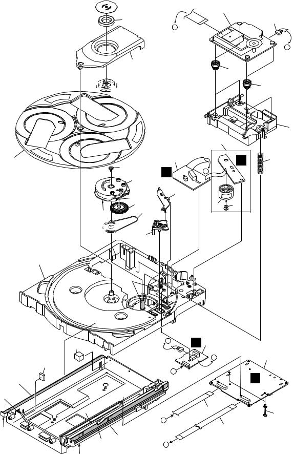
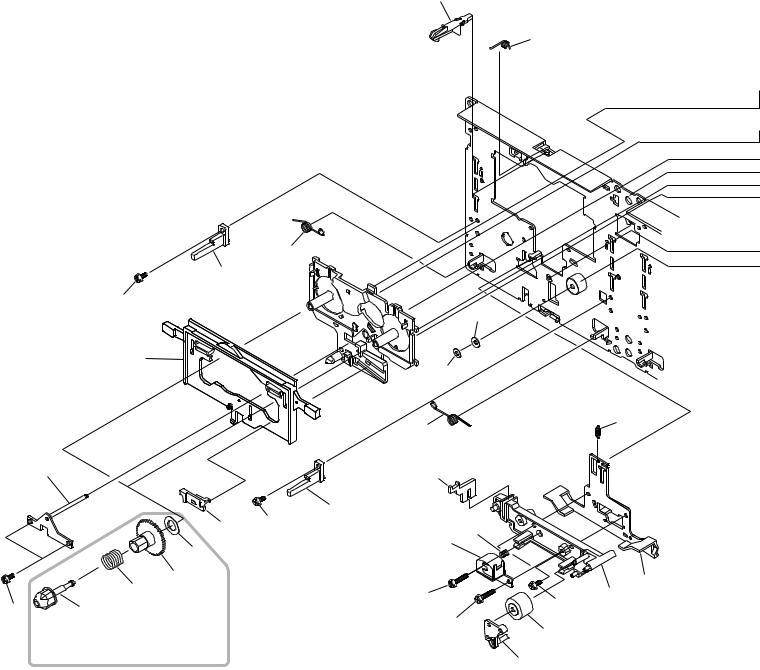
XR-VS90SW, XR-VS90, XR-VS70SW, XR-VS70
2.4 $M MECHANISM VCD
 8
8
7
14
 13
13
12
26
15
29
18
29 |
6 |
|
16 

17
10
29
32
30
29
29
29
29
9
29
Refer to
25 "2.5 SERVO MECHANISM ASSY".
22
A
D
24
23
11
|
1 |
|
2 |
C |
5 |
|
|
D  C
C
19
27 28
D |
E 4 |
|
|
|
|
|
C |
3 |
|
B |
|
B
21 20
A
31
B
29
8
XR-VS90SW, XR-VS90, XR-VS70SW, XR-VS70
(1) $M MECHANISM VCD PARTS LIST
Mark |
No. |
Description |
|
Part No. |
Mark No. |
Description |
|
Part No. |
|
|
1 |
MOTOR Assy |
|
XWZ3080 |
|
16 |
Gear Pulley |
|
ANW7094 |
|
2 |
SW Assy |
|
XWZ3081 |
17 |
Lock Lever |
|
ANW7095 |
|
NSP |
3 |
$M SERVO VCD Assy |
|
See Contrast table (2) |
18 |
Planet Gear |
|
ANW7096 |
|
|
4 |
TRADE Assy |
|
XWZ3082 |
19 |
Actuator |
|
ANW7097 |
|
|
5 |
Servo Spring |
|
ABH7126 |
20 |
Mini Card Spacer |
|
AEC7143 |
|
|
6 |
Belt |
|
AEB7072 |
21 |
15P Flexible Cable/30V |
|
XDD3007 |
|
|
7 |
Clamp Magnet |
|
AMF7001 |
22 |
Connector Assy (6P) |
|
ADE7010 |
|
|
8 |
Yoke |
|
ANB7216 |
23 |
Float Rubber A |
|
AEB7063 |
|
|
9 |
Mecha Base |
|
XNW3011 |
24 |
Float Rubber B |
|
AEB7066 |
|
|
10 |
Loading Tray |
|
XNW3002 |
25 |
Servo Mechanism Assy |
|
XXA3015 |
|
|
11 |
Servo Base |
|
XNW3012 |
26 |
Screw |
|
IPZ30P080FMC |
|
|
12 |
Rotary Tray |
|
ANW7113 |
27 |
Carriage Motor |
|
VXM1033 |
|
|
13 |
Clamper |
|
ANW7091 |
28 |
Motor Pulley |
|
PNW1634 |
|
|
14 |
Clamper Holder |
|
XNW3004 |
29 |
Ha Narl |
|
GEM1016 |
|
|
15 |
Main Cam |
|
ANW7093 |
30 |
Cushion Rubber |
|
XEB3005 |
|
|
|
|
|
|
31 |
13P Flexible Cable/30V |
|
XDD3008 |
|
(2) CONTRAST TABLE
$M MECHANISM VCD (XXA3017) and (XXA3016) are constructed the same except for the following :
|
|
|
Part No. |
|
|
Mark |
No. |
Symbol and Description |
|
|
Remarks |
XXA3017 |
XXA3016 |
||||
|
|
|
(XR-VS90SW, XR-VS90) |
(XR-VS70SW, XR-VS70) |
|
|
|
|
|
|
|
|
3 |
$M SERVO VCD Assy |
XWX3018 |
XWX3017 |
|
|
|
|
|
|
|
9

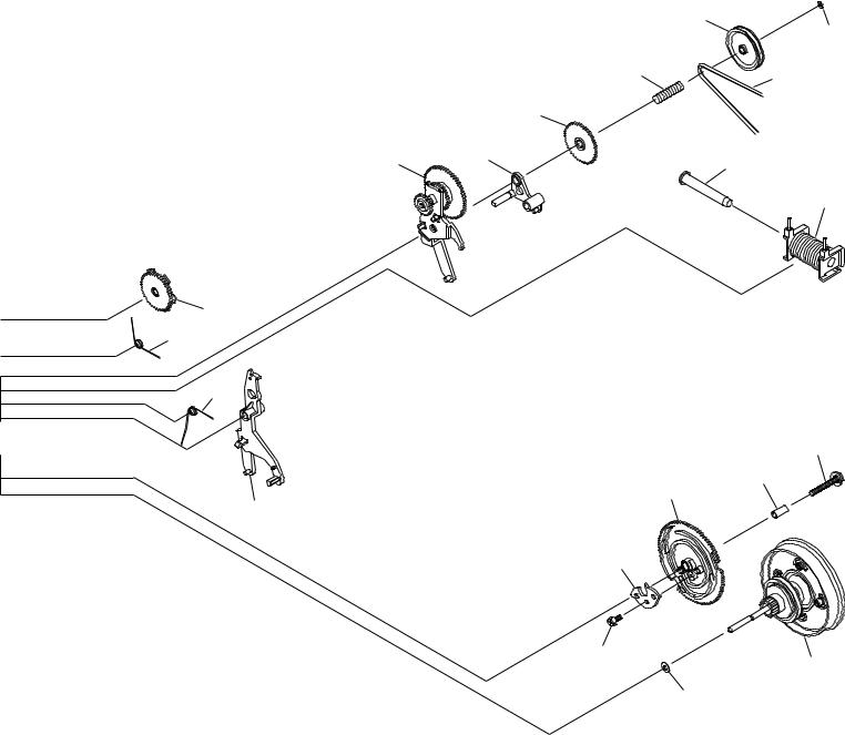
XR-VS90SW, XR-VS90, XR-VS70SW, XR-VS70
2.5 SERVO MECHANISM ASSY
∙ SERVO MECHANISM ASSY PARTS LIST
Mark No. |
Description |
|
Part No. |
|
|
1 |
Servo Mechanism Assy |
|
XXA3015 |
2 |
Spindle Motor Assy |
|
AEA7009 |
|
3 |
Sled Motor Assy |
|
AEA7010 |
|
4 |
Gear A |
|
AEA7013 |
|
5 |
Gear B |
|
AEA7014 |
|
6 |
Screw |
|
AEA7015 |
|
7 |
Screw |
|
AEA7016 |
|
8 |
Screw |
|
AEA7017 |
|
9 |
Screw |
|
AEA7018 |
|
10 |
Leaf Switch |
|
AEA7011 |
|
10
XR-VS90SW, XR-VS90, XR-VS70SW, XR-VS70
2.6 DECK MECHANISM UNIT
2.6.1 XYM3012
∙ DECK MECHANISM UNIT (XYM3012) PARTS LIST
Mark No. |
Description |
|
Part No. |
Mark No. |
Description |
|
Part No. |
||
|
1 |
Assy’y HD Holder |
|
50-093-4373 |
|
60 |
Spring |
|
01-081-4601 |
2 |
Assy’y HD Holder |
50-093-4104 |
|
|
|
|
|
||
3 |
Frame HD |
50-219-3024 |
61 |
Spring |
01-082-4652 |
||||
4 |
Plate AZ |
50-119-4046 |
62 |
Spring |
01-082-4651 |
||||
5 |
Spring AZ |
50-160-4108 |
63 |
Spring |
01-082-4650 |
||||
|
|
|
|
|
64 |
Spring |
01-080-4649 |
||
6 |
Lever HD |
50-259-3342 |
65 |
Spring |
01-080-4607 |
||||
11 |
Chassis HD |
50-112-3045 |
66 |
Spring |
01-080-4635 |
||||
12 |
Cap Pinch R |
50-219-4033 |
67 |
Spring |
01-082-4654 |
||||
13 |
Cap Pinch L |
50-219-4034 |
68 |
Spring |
01-082-4598 |
||||
14 |
Roller Pinch |
50-027-41054 |
69 |
Spring |
01-082-4597 |
||||
15 |
Ass’y Plate D |
50-219-4311 |
70 |
Spring |
01-081-4657 |
||||
16 |
Cap Reel |
50-228-4020 |
80 |
Screw |
|
GSE10A2003 |
|||
17 |
Gear Reel |
50-222-4006 |
|
|
|
|
|
||
18 |
Lever ST |
50-259-4041 |
81 |
Screw |
|
GSE20A2005 |
|||
19 |
Guide C |
50-219-4014 |
82 |
Screw |
|
GSE10A2004 |
|||
20 |
Lever Brake |
50-259-3251 |
83 |
Screw |
|
GSD10A2018 |
|||
|
|
|
|
|
84 |
Screw |
03-300-4056 |
||
22 |
Arm SW |
50-239-4027 |
85 |
Screw |
|
GSL10A1704 |
|||
23 |
Arm CS |
50-239-4026 |
|
|
|
|
|
||
25 |
Ass’y Cover |
50-093-4063 |
86 |
Screw |
|
GSP10A2603 |
|||
|
|
|
|
|
87 |
Screw |
|
GSP11A2012 |
|
26 |
Ass’y Flywheel LA |
50-093-3366 |
88 |
Screw |
|
GSE20A2004 |
|||
27 |
Arm Trigger |
50-268-3016 |
|
|
|
|
|
||
28 |
Arm Cam |
50-139-4292 |
100 |
Washer |
|
GWN21X040040 |
|||
29 |
Gear Cam |
50-221-3009 |
|
|
|
|
|
||
30 |
Coller |
03-300-4455 |
101 |
Washer |
|
GWM19X055035S |
|||
|
|
|
|
|
102 |
Washer |
|
GWM19S035035 |
|
31 |
Ass’y Flywheel RA |
50-093-3360 |
103 |
Washer |
|
GWM17S050035S |
|||
32 |
Ass’y Clutch |
50-093-4069 |
104 |
Washer |
|
GWM48X075010 |
|||
33 |
Arm UD A |
50-239-4017 |
105 |
Washer |
|
GWP23X040020 |
|||
34 |
Gear UD |
50-222-4007 |
|
|
|
|
|
||
35 |
Pulley D |
50-223-4254 |
106 |
Washer |
|
GWP21X045020 |
|||
36 |
Plunger |
03-300-4442 |
107 |
Washer |
|
GWP12X030040S |
|||
|
|
|
|
|
|||||
37 |
Ass’y Bobbin |
50-093-4125 |
|
|
|
|
|
||
39 |
Ass’y Motor |
50-093-4316 |
|
|
|
|
|
||
41 |
Belt BR |
02-084-4205 |
|
|
|
|
|
||
42 |
Belt AR |
02-084-4203 |
|
|
|
|
|
||
43 |
Belt FR |
02-083-4188 |
|
|
|
|
|
||
45 |
PCB HD |
50-070-4057 |
|
|
|
|
|
||
46 |
Housing |
|
S5BPHKS |
|
|
|
|
|
|
47 |
Housing |
|
S3BPHKS |
|
|
|
|
|
|
48 |
Pulley IDL |
50-223-4023 |
|
|
|
|
|
||
50 |
Ass’y PCB |
50-093-4363 |
|
|
|
|
|
||
51 |
Ass’y Flywheel L |
50-093-3367 |
|
|
|
|
|
||
52 |
Ass’y Flywheel RB |
50-093-3361 |
|
|
|
|
|
||
53 |
Pulley |
33-229-4264 |
|
|
|
|
|
||
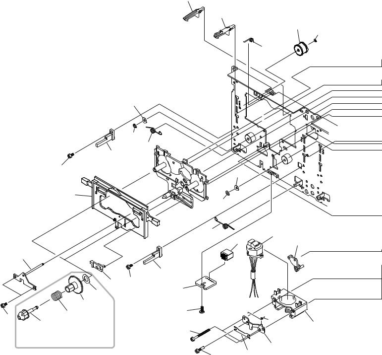
11

XR-VS90SW, XR-VS90, XR-VS70SW, XR-VS70
• DECK MECHANISM UNIT (1/2)
22
101
100
61
19
81
20
|
15 |
|
|
|
|
81 |
19 |
|
|
18 |
|
|
|
|
|
|
104 |
|
45 |
|
|
|
|
|
17 |
|
|
|
60 |
|
88 |
|
|
|
|
80 |
16 |
|
83 |
Note : When part #17 or #60 or #104 is |
|
||
|
|
replaced, part #16 also need to be replaced at the same time.
84
42
41
23
67
|
103 |
|
|
102 |
|
62 |
1 |
|
13 |
||
|
||
|
46 |
63
3
4
5
12

XR-VS90SW, XR-VS90, XR-VS70SW, XR-VS70
14
64
80 |
|
|
|
39 |
35 |
86 |
|
|
|
|
|
|
|
107 |
|
70 |
43 |
80 |
|
|
|
34 |
|
32 |
33 |
36 |
|
|
|
|
|
37 |
105 51
25
82
68
69
50
87
30
29
27
66 |
28 |
85
6
106 |
52 |
|
65
14
11
12
13
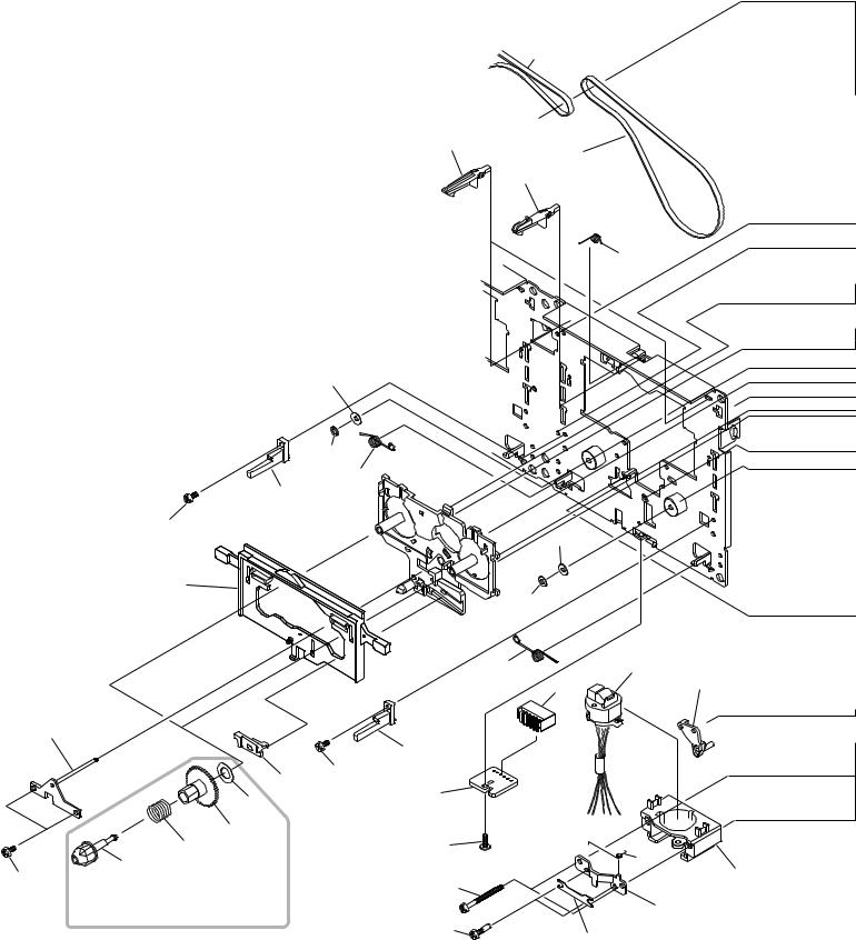
XR-VS90SW, XR-VS90, XR-VS70SW, XR-VS70
• DECK MECHANISM UNIT (2/2)
22
23
53
107
67
101
100
61
19 |
|
|
81 |
|
|
|
103 |
|
20 |
|
|
|
102 |
|
|
62 |
2 |
|
47 |
|
|
13 |
|
|
|
|
15 |
|
|
|
19 |
|
18 |
81 |
|
|
|
|
104 |
45 |
|
|
|
|
17 |
|
|
60 |
82 |
|
|
|
|
80 |
|
63 |
16 |
|
|
|
3 |
|
Note : When part #17 or #60 or #104 is |
83 |
|
replaced, part #16 also need to |
|
|
be replaced at the same time.
|
4 |
84 |
5 |
|
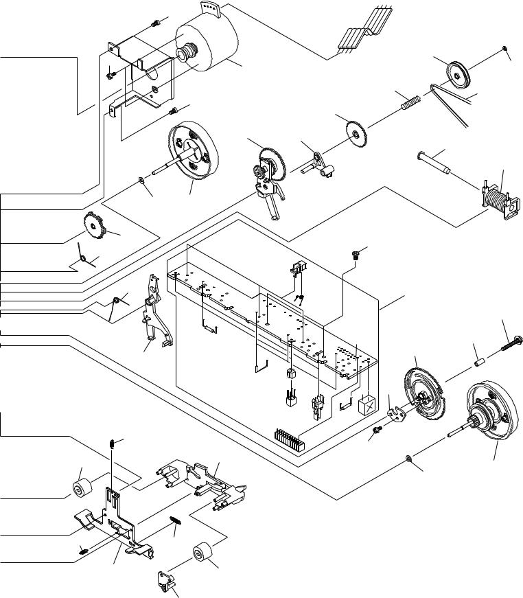
14

XR-VS90SW, XR-VS90, XR-VS70SW, XR-VS70
14
64
|
|
|
35 |
|
|
|
107 |
|
|
70 |
43 |
|
|
|
|
|
|
34 |
|
32 |
33 |
|
36 |
|
|
||
|
|
|
|
|
|
|
37 |
26
105
25
68
69 48 107
87
30
29
27 |
28 |
|
66
6 |
85 |
|
31
106
65
11 |
14 |
|
12
15
XR-VS90SW, XR-VS90, XR-VS70SW, XR-VS70
2.6.2 XYM3011
• DECK MECHANISM UNIT (1/2)
42
22
41
23
67
101
100
61
19
81
|
|
103 |
|
20 |
|
|
|
|
|
102 |
|
|
62 |
|
1 |
|
|
46 |
13 |
|
|
|
|
15 |
|
|
|
|
19 |
|
|
|
81 |
|
|
|
18 |
|
|
104 |
45 |
|
|
|
|
|
|
17 |
|
|
|
60 |
88 |
|
|
|
|
63 |
|
16 |
|
|
|
|
|
3 |
|
80 |
83 |
|
|
|
|
||
Note : When part #17 or #60 or #104 is |
|
|
replaced, part #16 also need to
be replaced at the same time. |
|
4 |
|
|
|
|
84 |
5 |
|
|
16
XR-VS90SW, XR-VS90, XR-VS70SW, XR-VS70
14
64
80 |
|
|
86 |
35 |
|
107 |
||
39 |
||
|
70 |
|
|
43 |
|
80 |
|
|
|
34 |
|
32 |
33 |
|
|
36 |
|
|
37 |
105 51
25
82
68
69
50
87
30
29
27
28
66
85
6
52
106
65
11 |
14 |
12
17
XR-VS90SW, XR-VS90, XR-VS70SW, XR-VS70
• DECK MECHANISM UNIT (2/2)
23
67
61
19
81
103
20
102
66
62
15
9
|
|
19 |
|
|
|
18 |
81 |
71 |
|
|
|
|
||
|
104 |
|
7 |
|
|
|
|
|
|
60 |
17 |
|
|
11 |
|
90 |
81 |
10 |
|
|
|
|||
|
|
|
|
80 16
Note : When part #17 or #60 or #104 is |
89 |
|
14 |
||
replaced, part #16 also need to |
||
|
||
be replaced at the same time. |
12 |
|
|
18
XR-VS90SW, XR-VS90, XR-VS70SW, XR-VS70
|
|
35 |
|
|
107 |
|
70 |
43 |
|
34 |
|
32 |
33 |
36 |
|
||
|
|
37 |
25
68
69
87
30
29
27
28
85
31
106
19
XR-VS90SW, XR-VS90, XR-VS70SW, XR-VS70
∙ DECK MECHANISM UNIT (XYM3011) PARTS LIST
Mark No. |
Description |
|
Part No. |
Mark No. |
Description |
|
Part No. |
||
|
1 |
Assy’y HD Holder |
|
50-093-4373 |
|
60 |
Spring |
|
01-081-4601 |
3 |
Frame HD |
50-219-3024 |
|
|
|
|
|
||
4 |
Plate AZ |
50-119-4046 |
61 |
Spring |
01-082-4652 |
||||
5 |
Spring AZ |
50-160-4108 |
62 |
Spring |
01-082-4651 |
||||
|
|
|
|
|
63 |
Spring |
01-082-4650 |
||
6 |
Lever HD |
50-259-3342 |
64 |
Spring |
01-080-4649 |
||||
7 |
R/P Head |
|
TC881CB067B |
65 |
Spring |
01-080-4607 |
|||
9 |
Guide Tape |
50-219-4038 |
|
|
|
|
|
||
10 |
Plate HD |
50-093-3036 |
66 |
Spring |
01-080-4635 |
||||
|
|
|
|
|
67 |
Spring |
01-082-4654 |
||
11 |
Chassis HD |
50-112-3045 |
68 |
Spring |
01-082-4598 |
||||
12 |
Cap Pinch R |
50-219-4033 |
69 |
Spring |
01-082-4597 |
||||
13 |
Cap Pinch L |
50-219-4034 |
70 |
Spring |
01-081-4657 |
||||
14 |
Roller Pinch |
50-027-41054 |
|
|
|
|
|
||
15 |
Ass’y Plate D |
50-219-4311 |
71 |
Spring |
01-081-4605 |
||||
16 |
Cap Reel |
50-228-4020 |
80 |
Screw |
|
GSE10A2003 |
|||
17 |
Gear Reel |
50-222-4006 |
|
|
|
|
|
||
18 |
Lever ST |
50-259-4041 |
81 |
Screw |
|
GSE20A2005 |
|||
19 |
Guide C |
50-219-4014 |
82 |
Screw |
|
GSE10A2004 |
|||
20 |
Lever Brake |
50-259-3251 |
83 |
Screw |
|
GSD10A2018 |
|||
|
|
|
|
|
84 |
Screw |
03-300-4056 |
||
22 |
Arm SW |
50-239-4027 |
85 |
Screw |
|
GSL10A1704 |
|||
23 |
Arm CS |
50-239-4026 |
|
|
|
|
|
||
25 |
Ass’y Cover |
50-093-4063 |
86 |
Screw |
|
GSP10A2603 |
|||
|
|
|
|
|
87 |
Screw |
|
GSP11A2012 |
|
27 |
Arm Trigger |
50-268-3016 |
88 |
Screw |
|
GSE20A2004 |
|||
28 |
Arm Cam |
50-139-4292 |
89 |
Screw |
|
GSL20A2005 |
|||
29 |
Gear Cam |
50-221-3009 |
90 |
Screw |
03-300-4127 |
||||
30 |
Coller |
03-300-4455 |
100 |
Washer |
|
GWN21X040040 |
|||
31 |
Ass’y Flywheel RA |
50-093-3360 |
|
||||||
|
|
|
|
|
|||||
32 |
Ass’y Clutch |
50-093-4069 |
101 |
Washer |
|
GWM19X055035S |
|||
33 |
Arm UD A |
50-239-4017 |
102 |
Washer |
|
GWM19S035035 |
|||
34 |
Gear UD |
50-222-4007 |
103 |
Washer |
|
GWM17S050035S |
|||
35 |
Pulley D |
50-223-4254 |
104 |
Washer |
|
GWM48X075010 |
|||
36 |
Plunger |
03-300-4442 |
105 |
Washer |
|
GWP23X040020 |
|||
|
|
|
|
|
|||||
37 |
Ass’y Bobbin |
50-093-4125 |
106 |
Washer |
|
GWP21X045020 |
|||
39 |
Ass’y Motor |
50-093-4316 |
107 |
Washer |
|
GWP12X030040S |
|||
41 |
Belt BR |
02-084-4205 |
|
|
|
|
|
||
42 |
Belt AF |
02-084-4202 |
|
|
|
|
|
||
43 |
Belt FR |
02-083-4188 |
|
|
|
|
|
||
45 |
PCB HD |
50-070-4057 |
|
|
|
|
|
||
46 |
Housing |
|
S5BPHKS |
|
|
|
|
|
|
50 |
Ass’y PCB |
50-093-4057 |
|
|
|
|
|
||
51 |
Ass’y Flywheel L |
50-093-3315 |
|
|
|
|
|
||
52 |
Ass’y Flywheel RB |
50-093-3361 |
|
|
|
|
|
||
20
XR-VS90SW, XR-VS90, XR-VS70SW, XR-VS70
21
A
B
C
D
1 |
|
2 |
|
3 |
|
4 |
|
|
|
|
|
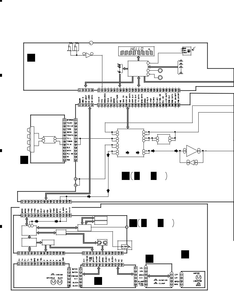
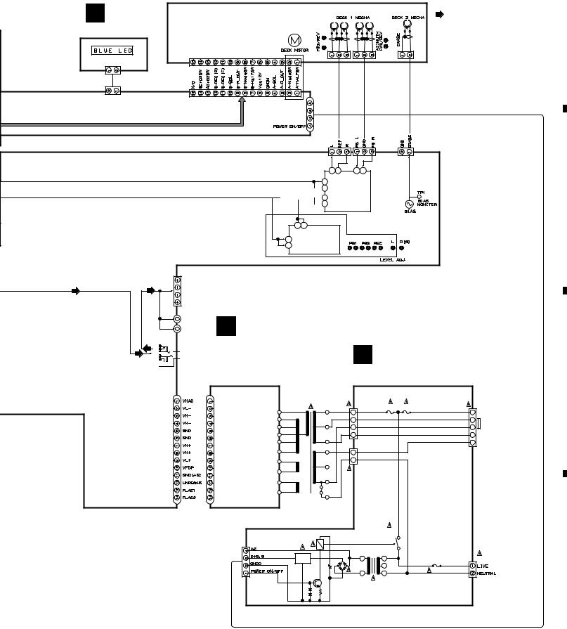
XR-VS90SW, XR-VS90, XR-VS70SW, XR-VS70
3. BLOCK DIAGRAM AND SCHEMATIC DIAGRAM
3.1 BLOCK DIAGRAM and OVERALL WIRING DIAGRAM |
||||
JA3902 |
MAIN |
MIC SUB |
JA3901 |
MICVOL |
|
|
|
||
|
|
|
|
|
|
X5901 |
|
|
|
V5621 |
|
|
|
I |
2 |
7 |
FL TUBE |
|
|
REMOTE |
|
|
|
|
|
RECEIVER |
|
|
IC3901 |
|
|
|
UNIT |
|
|
|
|
|
|
||
DISPLAY ASSY |
BA4558F-HT |
|
|
29 |
|
|
MIC AMP |
|
IC5501 |
|
|||
|
|
KEYs |
||||
|
|
|
|
|||
(XR-VS90SW : XWZ3315) |
|
|
LEDs |
PDC063A |
|
|
|
|
SYSTEM |
12 |
MAIN VOL |
||
|
|
|
||||
(XR-VS90 : XWZ3314) |
|
|
|
CONTROL |
13 |
|
|
|
|
|
|
||
|
|
|
|
|
|
|
(XR-VS70SW : XWZ3302) |
|
|
|
|
|
MORPHING JOG |
|
|
CD CONTROL |
|
|
DECK CONTROL |
|
(XR-VS70 : XWZ3301) |
|
|
|
|
|
|
CN5502
CN5106
CN6201 |
CN3051 |
BN6202 |
|
|
|
FM |
|
IC6201 |
|
|
LA1832ML |
||
|
1 |
FM |
L 14 |
|
2 |
AM |
R 15 |
AM |
|
|
|
A
FM/AM TUNER MODULE (DBDXJ : AXQ7062) (DLXJ/NC, DXJN/NC : AXQ7065)
L
AUX IN
R
JA3001
CN5501
CN5105
|
|
|
|
IC3836 |
|
|
|
|
|
|
|
|
|
BA3838F |
|
|
|
|
|
19 |
L |
|
L 60 |
VOCAL FADER |
|
|
|
||
DECK |
|
|
|
|
|
IC3301 |
|||
30 |
R |
R 53 |
|
|
|
|
|
||
|
|
|
|
|
|
|
STK407-090B |
||
17 |
L |
TUNER |
L 61 |
6 L |
L |
3 |
(XR-VS90SW, XR-VS90) |
||
32 |
R |
R 52 |
9 R |
R |
8 |
STK407-070B |
|||
|
|
|
|
|
|
|
(XR-VS70SW, XR-VS70) |
||
16 |
L AUX |
|
|
|
|
|
POWER AMP |
||
|
|
|
|
|
|
|
|||
33 |
R |
|
|
|
|
|
L 14 |
|
7 L |
21 |
L |
|
L 58 |
|
|
|
|
||
|
|
|
|
R 10 |
|
6 R |
|||
28 |
R CD |
R 55 |
|
|
|
|
|||
|
|
|
|
|
|
||||
|
|
IC3001 |
|
|
|
|
|
|
|
|
|
LC75394NED |
|
|
|
|
L |
7 |
5 L |
|
|
E-VOL IC |
|
|
|
|
R |
1 |
3 R |
IC3501, IC3502
BA4558F-HT
GODZILLA AMP
F F 1/3- F 3/3
AF ASSY
(XR-VS90SW, XR-VS90 : XWZ3313) (XR-VS70SW, XR-VS70 : XWZ3300)
CN1053
|
|
|
|
|
|
$M MECHANISM VCD |
|
|
|
|
|
|
|
(XR-VS90SW, XR-VS90 : XXA3017) |
|
|
|
CN1004 |
|
|
|
(XR-VS70SW, XR-VS70 : XXA3016) |
|
|
|
|
|
IC1751 |
|
||
|
|
|
ROM (1M) |
|
|
|
|
48 57 |
LC78632RE |
CL680T-D1 MPEG |
PEB001A |
|
B B 1/2, B 2/2 |
|
|
|
IC1752 |
|
|
||||
|
IC1201 |
IC1701 |
DRAM (4M) |
|
|
|
|
|
MB814260-70PJ |
|
|
||||
L R |
|
DECODER |
|
|
JA1701 $M SERVO VCD ASSY |
|
|
CD DSP |
|
VCD |
|
|
|
||
|
IC1301 |
U-COM |
LOADING |
|
|
(XR-VS90SW, XR-VS90 : XWX3018) |
|
|
IC1501 |
|
|
(XR-VS70SW, XR-VS70 : XWX3017) |
|||
IC1101 |
BA5923FP |
PDC067A |
DRIVER |
|
|
||
|
|
|
|
|
|
|
|
LA9240ML |
DRIVER |
|
|
|
JA1201 |
|
|
RF SERVO |
|
|
|
|
|
XR-VS90SW, XR-VS90 |
|
CN1001 |
|
CN1002 |
|
|
|
ONLY |
C |
|
|
|
|
|
|||
|
|
|
|
|
|
||
|
|
|
|
|
|
SW ASSY |
|
|
|
CN9002 |
|
|
|
D (XWZ3081) |
MOTOR |
|
|
|
|
|
|
CN9501 |
ASSY |
|
|
CN9001 |
|
|
|
J9501 |
|
SERVO MECHANISM |
|
|
|
(XWZ3080) |
|||
|
|
|
|
||||
|
|
|
|
J9502 |
|||
ASSY |
|
|
|
|
|
J9502 |
|
|
|
|
|
|
|
||
(XXA3015) |
|
|
|
|
|
|
|
E TRADE ASSY (XWZ3082)
22
|
1 |
|
2 |
|
3 |
|
4 |
|
|
|
|
|
|
||||
|
|
|
|
|
|
5 |
|
6 |
|
7 |
|
8 |
|
|
|
|
|
|
XR-VS90SW, XR-VS90, XR-VS70SW, XR-VS70
Note : When ordering service parts, be sure to refer to "EXPLODED VIEWS and PARTS LIST" or "PCB PARTS LIST".
J BLUEASSY LED (XWZ3292)
DECK MECHANISM UNIT |
: AUDIO SIGNAL ROUTE (CD) |
A |
|
(XR-VS90SW, XR-VS90 : XYM3012) |
|||
|
|||
(XR-VS70SW, XR-VS70 : XYM3011) |
|
|
J5602
XR-VS90SW,
XR-VS90
ONLY
J81
CN2301 |
|
|
CN2303 |
CN2302 |
2 |
3 |
8 |
9 |
|
L R |
L R |
|
||
19 L |
|
|
|
|
 18 R
18 R
IC2301


 27 L HA12211NT
  B
B
 26 R REC PB IC
XR-VS90SW, |
|
|
|
XR-VS90 |
9 |
8 |
|
ONLY |
L R |
||
L |
IC2201 |
||
16 |
|||
HA12136AF |
|||
1 |
R |
||
DOLBYNR IC |
|||
CN3331
L
SPEAKERS
R
JA3441
L
MATRIX
R
JA3991
 PHONES
G
SECONDARY ASSY |
H |
|
(XR-VS90SW, XR-VS90 |
|
|
: XWZ3304) |
|
|
(XR-VS70SW, XR-VS70 |
PRIMARY ASSY |
|
: XWZ3289) |
(XWZ3291) |
C |
J11 |
J11 |
CN2 |
FU3 FU2 |
4
3
2
1
|
|
CN1 |
FU2, FU3 |
|
|
2 |
XR-VS90SW, XR-VS90 : |
|
|
1 |
AEK1059 (T3.15A) |
|
|
XR-VS70SW, XR-VS70 : |
|
|
|
|
AEK1057 (T2A) |
T1 |
|
|
|
POWER |
|
|
|
TRANSFORMER |
|
|
|
XR-VS90SW, XR-VS90 : XTS3037 |
|
|
|
XR-VS70SW, XR-VS70 : XTS3036 |
|
|
|
RY81 |
|
|
RY81 |
CN81 |
|
|
FU1 |
|
|
|
XR-VS90SW, XR-VS90 : |
IC81 |
D81 |
T2 |
AEK1061 (T5A) |
XR-VS70SW, XR-VS70 : |
|||
|
|
|
AEK1060 (T4A) |
Q81
S1
AN1
D
AC IN
23
|
5 |
|
6 |
|
7 |
|
8 |
|
|
|
|
|
|
||||
|
|
|
|
|

|
1 |
|
2 |
|
3 |
|
4 |
|
|
|
|
|
|
XR-VS90SW, XR-VS90, XR-VS70SW, XR-VS70
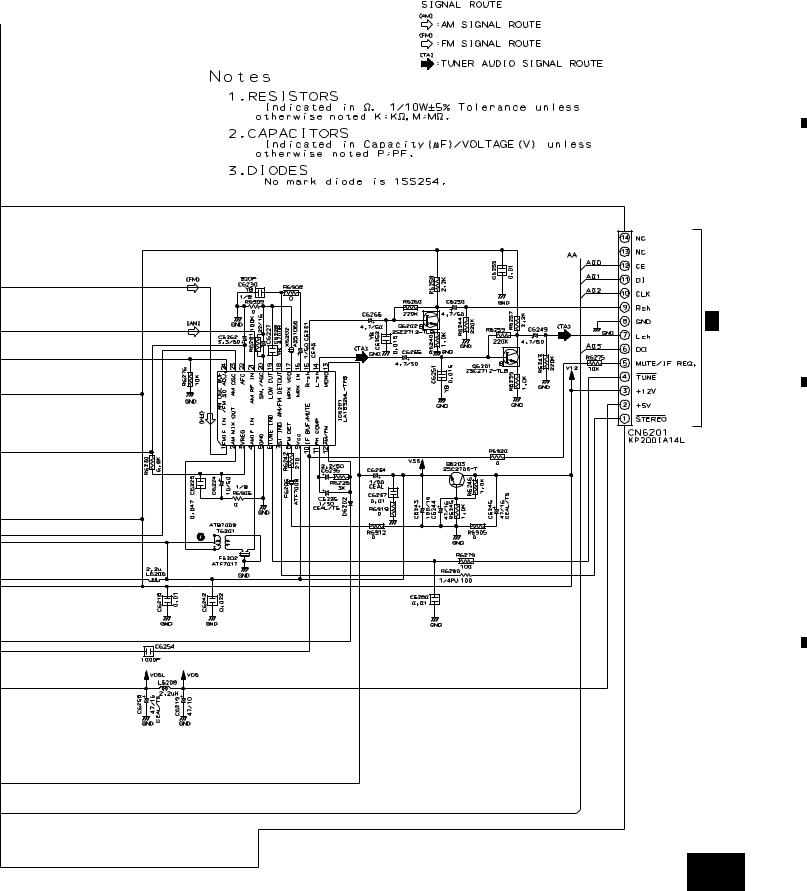
3.2 FM/AM TUNER MODULE (For DBDXJ Type)
A
AA FM/AM TUNER MODULE (AXQ7062)
MIX AMP
RF AMP
OSC
B
BUFFER
IF AMP
FM +B SW
AM RF TUNING BLOCK
C
SW DRIVE
PLL
D
24 AA
|
1 |
|
2 |
|
3 |
|
4 |
|
|
|
|
|
|
||||
|
|
|
|
|
|
5 |
|
6 |
|
7 |
|
8 |
|
|
|
|
|
|
XR-VS90SW, XR-VS90, XR-VS70SW, XR-VS70
A
B
AF AMP
F 2/3
CN3051
AF AMP
REGULATOR
C
D
AA 25
|
5 |
|
6 |
|
7 |
|
8 |
|
|
|
|
|
|
||||
|
|
|
|
|
|
1 |
|
2 |
|
3 |
|
4 |
|
|
|
|
|
|
XR-VS90SW, XR-VS90, XR-VS70SW, XR-VS70
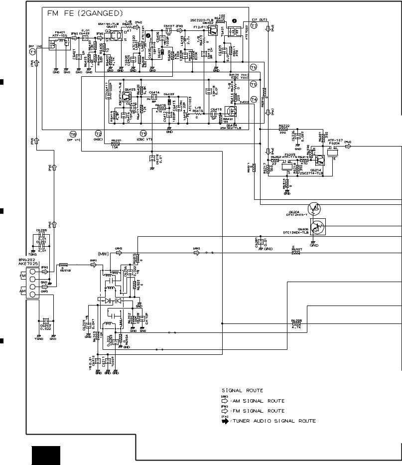
3.3 FM/AM TUNER MODULE (For DLXJ/NC and DXJN/NC Types)
A |
MIX AMP |
|
RF AMP |
||
|
1T378A
OSC
1T378A
BUFFER
B
IF AMP
FM +B SW
C
MW RF TUNING BLOCK
AXX7041
D
26 AB
|
1 |
|
2 |
|
3 |
|
4 |
|
|
|
|
|
|
||||
|
|
|
|
|
 Loading...