


ORDER NO.
RRV2793
XV-EV61
STEREO DVD TUNER DECK RECEIVER
XV-EV61
XV-EV31
THIS MANUAL IS APPLICABLE TO THE FOLLOWING MODEL(S) AND TYPE(S).
Model |
Type |
Power Requirement |
Regionalrestriction |
The voltage can be converted |
|
codes (Region No.) |
by the following method. |
||||
|
|
|
|||
|
|
|
|
|
|
XV-EV61 |
DLXJ/NC |
110-127V/220-230V/240V |
3 |
With the voltage selector |
|
|
|
|
|
|
|
XV-EV31 |
DLXJ/NC |
110-127V/220-230V/240V |
3 |
With the voltage selector |
|
|
|
|
|
|
This product is component of system.
Component |
System |
System |
Service manual |
||||||
|
|
|
|
|
|
|
|
|
|
MINI SYSTEM |
X-EV61D |
X-EV31D |
|
||||||
|
|
|
|
|
|
|
|
|
|
Stereo DVD Tuner Deck Receiver |
XV-EV61 |
XV-EV31 |
RRV2793(This manual) |
||||||
|
|
|
|
|
|
|
|
|
|
Speaker System |
S-EV61V |
S-EV31V |
RRV2776(EV61), RRV2800(EV31) |
||||||
|
|
|
|
|
|
|
|
|
|
|
|
|
|
|
|
|
|
|
|
|
|
|
|
|
|
|
|
|
|
|
|
|
|
|
|
|
|
|
|
|
|
|
|
|
|
|
|
|
|
|
|
|
|
|
|
|
|
|
|
For details, refer to "Important symbols for good services" .
PIONEER CORPORATION 4-1, Meguro 1-chome, Meguro-ku, Tokyo 153-8654, Japan
PIONEER ELECTRONICS (USA) INC. P.O. Box 1760, Long Beach, CA 90801-1760, U.S.A.
PIONEER EUROPE NV Haven 1087, Keetberglaan 1, 9120 Melsele, Belgium
PIONEER ELECTRONICS ASIACENTRE PTE. LTD. 253 Alexandra Road, #04-01, Singapore 159936
 PIONEER CORPORATION 2003
T-ZZR JULY 2003 printed in Japan

1 |
2 |
3 |
4 |
SAFETY INFORMATION
A
This service manual is intended for qualified service technicians ; it is not meant for the casual do- it-yourselfer. Qualified technicians have the necessary test equipment and tools, and have been trained to properly and safely repair complex products such as those covered by this manual. Improperly performed repairs can adversely affect the safety and reliability of the product and may void the warranty. If you are not qualified to perform the repair of this product properly and safely, you should not risk trying to do so and refer the repair to a qualified service technician.
WARNING !
B
THE AEL (ACCESSIBLE EMISSION LEVEL) OF THE LASER POWER OUTPUT IS LESS THAN CLASS 1
BUT THE LASER COMPONENT IS CAPABLE OF EMITTING RADIATION EXCEEDING THE LIMIT FOR
CLASS 1.
A SPECIALLY INSTRUCTED PERSON SHOULD DO SERVICING OPERATION OF THE APPARATUS.
LASER DIODE CHARACTERISTICS
FOR DVD : MAXIMUM OUTPUT POWER : 5 mW
WAVELENGTH : 650 nm
FOR CD : MAXIMUM OUTPUT POWER : 7 mW
WAVELENGTH : 780 nm
C
LABEL CHECK
D
STANDBY/ON |
|
|
|
SOUND |
MODE |
|
|
ADVANCED |
PGM |
|
|
SURROUND |
|
||
SURROUND |
ADV. RDM |
SFC |
|
REC |
|||
|
|
LINESURR.RPT–1 |
|
|
|
|
MONO |
|
|
|
RDSSTEREO |
|
|
|
96kTUNEDHz |
ECHONR |
B. |
|
|
|
KEYCUT |
REC |
|
|
KARAOKE L R |
WAKE–UPASES |
|
D |
|
|
|
VD/CD |
|
|
REC |
|
TAPE |
|
|
|
|
|
TUNER |
LINE
KARAOKE |
|
|
|
DOLBY |
|
|
|
(DEMO)NR |
|
|
|
ASES |
4 |
3/ |
|
TUNING1– |
|
8 |
|
|
|
|
¡ |
|
|
7 |
TUNING¢+ |
|
STEREO |
|
|
|
|
DECKDVD |
|
|
|
EV61RECEIVERCASSETTE |
|
|
|
|
DVD |
E
FULL |
|
AUTO |
STEREO |
||
|
LOGIC |
|
|
|
CASSETTEREVERSE |
|
|
DECK |
|
|
MIC VOL |
|
|
PHONES |
TIMER/CLOCK ADJ |
|
SYSTEM |
DISPLAY |
|
|
ST. |
MEMORY |
|
|
|
ENTER |
V |
OLUME |
OPEN/CLOSE |
|
REVERSE |
|
MODE |
|
REC/STOP |
|
PUSH |
OPEN |
F
(Printed on the Rear Panel B)
XV-EV61/DLXJ/NC
Additional Laser Caution
1.Laser Interlock Mechanism
•Loading switch (S101 on the LOAB Assy) is used for interlock mechanism of the laser.
When this switch turned ON in SW2 (XCLOSE) side (OPEN signal is 0V and XCLOSE signal is 3.5V), a laser becomes the status which can completely oscillation.
Furthermore, the laser completely oscillates in the disc judgment and disc playback.
When player is power ON state and laser diode is not completely oscillating, 780nm laser diode is always oscillating by half power.
•Laser diode is driving with Q101 (650nm LD) and Q102 (780nm LD) on the DVDM Assy.
Therefore, when short-circuit between the emitter and collector of these transistors or the base voltage is supplied for transistors turn on, the laser oscillates. (failure mode)
•In the test mode , there is the mode that the laser oscillates except for the disc judgment and playback. LD ON mode in the test mode oscillates with the laser forcibly.
The interlock mechanism mentioned above becomes invalid in this mode.
2.When the cover is open, close viewing through the objective lens with the naked eye will cause exposure to the laser beam.
: See page 107
2 |
|
XV-EV61 |
|
|
1 |
2 |
|
3 |
4 |

5 |
6 |
7 |
8 |
[ Important symbols for good services ]
In this manual, the symbols shown-below indicate that adjustments, settings or cleaning should be made securely.
When you find the procedures bearing any of the symbols, be sure to fulfill them:
1. Product safety
You should conform to the regulations governing the product (safety, radio and noise, and other regulations), and should keep the safety during servicing by following the safety instructions described in this manual.
2. Adjustments
To keep the original performances of the product, optimum adjustments or specification confirmation is indispensable. In accordance with the procedures or instructions described in this manual, adjustments should be performed.
3. Cleaning
For optical pickups, tape-deck heads, lenses and mirrors used in projection monitors, and other parts requiring cleaning, proper cleaning should be performed to restore their performances.
4. Shipping mode and shipping screws
A
B
To protect the product from damages or failures that may be caused during transit, the shipping mode should be set or the shipping screws should be installed before shipping out in accordance with this manual, if necessary.
5. Lubricants, glues, and replacement parts
Appropriately applying grease or glue can maintain the product performances. But improper lubrication or applying
 glue may lead to failures or troubles in the product. By following the instructions in this manual, be sure to apply the
 prescribed grease or glue to proper portions by the appropriate amount.For replacement parts or tools, the prescribed ones should be used.
Discs compatible with this player
Any disc that displays one of the following logos should play in this player. Other formats, including DVD-Audio, DVD-RAM, DVD-ROM, CD-ROM (except those that contain MP3 and WMA files), SACD will not play.
DVD-Video DVD-R DVD-RW
Audio-CD Video-CD |
CD-R * |
CD-RW * |
|
|
|
|
|
|
|
|
|
Super Video CD (Super VCD)
Fuji Color-CD
C
D
E
F
|
|
|
|
|
|
|
|
|
XV-EV61 |
7 |
3 |
||
5 |
6 |
|
|
|
8 |
|
1 2 3 4
CONTENTS
|
SAFETY INFORMATION..................................................................................................................................... |
2 |
|
A |
1. SPECIFICATIONS ............................................................................................................................................ |
5 |
|
2. EXPLODED VIEWS AND PARTS LIST |
6 |
||
|
|||
|
2.1 PACKING ................................................................................................................................................... |
6 |
|
|
2.2 EXTERIOR SECTION................................................................................................................................ |
8 |
|
|
2.3 AMP SECTION ........................................................................................................................................ |
10 |
|
|
2.4 FRONT PANEL SECTION ....................................................................................................................... |
12 |
|
|
2.5 LOADING MECHANISM ASSY ............................................................................................................... |
14 |
|
|
2.6 TRAVERSE MECHANISM ASSY............................................................................................................. |
16 |
|
|
2.7 DECK MECHANISM ASSY ..................................................................................................................... |
18 |
|
|
3. BLOCK DIAGRAM AND SCHEMATIC DIAGRAM .......................................................................................... |
20 |
|
|
3.1 OVERALL BLOCK DIAGRAM.................................................................................................................. |
20 |
|
|
3.2 DVD SECTION BLOCK DIAGRAM.......................................................................................................... |
22 |
|
B |
3.3 OVERALL WIRING DIAGAM ................................................................................................................... |
24 |
|
3.4 FM/AM TUNER MODULE |
28 |
||
|
|||
|
3.5 DVDM ASSY(1/3)..................................................................................................................................... |
30 |
|
|
3.6 DVDM ASSY(2/3)..................................................................................................................................... |
32 |
|
|
3.7 DVDM ASSY(3/3)..................................................................................................................................... |
34 |
|
|
3.8 DECK ASSY ............................................................................................................................................ |
36 |
|
|
3.9 IF/AF ASSY(1/3) ...................................................................................................................................... |
38 |
|
|
3.10 IF/AF ASSY(2/3) .................................................................................................................................... |
40 |
|
|
3.11 IF/AF ASSY(3/3) .................................................................................................................................... |
42 |
|
|
3.12 DSP ASSY(1/2)...................................................................................................................................... |
44 |
|
|
3.13 DSP ASSY (2/2)..................................................................................................................................... |
46 |
|
|
3.14 DISP ASSY ............................................................................................................................................ |
48 |
|
C |
3.15 MIC ASSY.............................................................................................................................................. |
50 |
|
3.16 EVOL ASSY |
52 |
||
|
|||
|
3.17 MOD. AMP ASSY................................................................................................................................... |
54 |
|
|
3.18 SP-TERMINAL and TRADE ASSYS...................................................................................................... |
56 |
|
|
3.19 PRIMARY ASSY .................................................................................................................................... |
58 |
|
|
3.20 SECONDARY ASSY .............................................................................................................................. |
60 |
|
|
4. PCB CONNECTION DIAGRAM ..................................................................................................................... |
62 |
|
|
4.1 LOAB ASSY ............................................................................................................................................. |
62 |
|
|
4.2 FM/AM TUNER MODULE........................................................................................................................ |
63 |
|
|
4.3 DVDM ASSY ............................................................................................................................................ |
64 |
|
|
4.4 IF/AF ASSY.............................................................................................................................................. |
66 |
|
|
4.5 DSP ASSY (XV-EV61 Only)..................................................................................................................... |
70 |
|
D |
4.6 MIC ASSY................................................................................................................................................ |
71 |
|
|
4.7 DECK ASSY ............................................................................................................................................ |
72 |
|
|
4.8 DISP1, DISP2 and DISP3 ASSYS........................................................................................................... |
74 |
|
|
4.9 EVOL ASSY ............................................................................................................................................. |
76 |
|
|
4.10 SP-TERMINAL and TRADE ASSYS...................................................................................................... |
80 |
|
|
4.11 MOD. AMP ASSY................................................................................................................................... |
82 |
|
|
4.12 PRIMARY ASSY .................................................................................................................................... |
84 |
|
|
4.13 SECONDARY......................................................................................................................................... |
86 |
|
|
5. PCB PARTS LIST ........................................................................................................................................... |
88 |
|
|
6. ADJUSTMENT ............................................................................................................................................. |
101 |
|
|
6.1 DECK SECTION .................................................................................................................................... |
101 |
|
|
6.1.1 Adjustment condition ....................................................................................................................... |
101 |
|
E |
6.1.2 Playback and Recording section ..................................................................................................... |
102 |
|
|
6.2 TUNER SECTION.................................................................................................................................. |
104 |
|
|
6.3 DVD SECTION ADJUSTMENT ITEMS ana LOCATION........................................................................ |
105 |
|
|
6.4 JIGS and MEASURING INSTRUMENTS .............................................................................................. |
105 |
|
|
6.5 NECESSARY ADJUSTMENT POINTS ................................................................................................. |
106 |
|
|
6.6 TEST MODE .......................................................................................................................................... |
107 |
|
|
6.7 MECHANISM ADJUSTMENT ................................................................................................................ |
108 |
|
|
7. GENERAL INFORMATION........................................................................................................................... |
110 |
|
|
7.1 DIAGNOSIS ........................................................................................................................................... |
110 |
|
|
7.2 PARTS.................................................................................................................................................... |
145 |
|
|
7.3 CLEANING............................................................................................................................................. |
158 |
|
F |
8. PANEL FACILITIES ...................................................................................................................................... |
159 |
|
|
|
4 |
|
XV-EV61 |
|
|
1 |
2 |
|
3 |
4 |

5 |
6 |
1. SPECIFICATIONS
Specifications
Amplifier Section
X-EV61DVD model
Continuous power output: |
|
|
Front . . . . . . . . . . |
. . . . . . . . . . . 75 W per channel |
|
|
(1kHz, 10 % T.H.D., 6 |
Ω) |
Center . . . . . . . . |
. 75 W (1kHz, 10 % T.H.D., 6 Ω) |
|
Surround . . . . . . |
. . . . . . . . . . . 75 W per channel |
|
|
(1kHz, 10 % T.H.D., 6 |
Ω) |
Subwoofer . . . . . |
75 W (100Hz, 10 % T.H.D., 6 |
Ω) |
X-EV31DVD model |
|
|
Front . . . . . . . . . . |
. . . . . . . . . . . . . . . . 75 W + 75W |
|
|
(1 kHz, 10 % T.H.D., 6 |
Ω) |
Subwoofer . . . . |
100 W (100Hz, 10 % T.H.D., 6 |
Ω) |
Disc section
Digital audio |
|
characteristics . . . . . . . . . |
DVD fs: 96 kHz, 24-bit |
Type .DVD system, Video CD/Super VCD system |
|
and Compact Disc digital audio system |
|
Frequency response . . . . . |
. . . . . . 4 Hz to 44 kHz |
S/N ratio . . . . . . . . . . . . . . |
. . . . . . . . . . . . . .95 dB |
Dynamic range . . . . . . . . . |
. . . . . . . . . . . . . .95 dB |
Total harmonic distortion . |
. . . . . . . . . . . . 0.005 % |
Wow and Flutter . . . . . . . . |
Limit of measurement |
(±0.001 % W.PEAK) or less (JEITA)
Cassette deck section
Systems . . . . . . . . . . . . 4 track, 2-channel stereo Heads . . . . . . . . . . . Recording/playback head x 1 Erasing head x 1 Motor . . . . . . . . . . . . . . . . . . . DC servo motor x 1
Tape types . . . . . . . . . . . . . . . . . . Type I (Normal)
FM tuner section
Frequency range . . . . . . . . . . . . |
. . 87.5 – 108MHz |
Antenna . . . . . . . . . . . . . . . . . . |
75 Ω, unbalanced |
AM tuner section
Frequency range
With 9 kHz step . . . . . . . . 531 kHz to 1,602 kHz With 10 kHz step . . . . . . . 530 kHz to 1,700 kHz Antenna . . . . . . . . . . . . . . . . . . . . . . Loop antenna
Manufactured |
under |
license from |
Dolby |
Laboratories. |
“Dolby” , |
“Pro Logic” |
, and the |
double-D symbol are trademarks of Dolby Laboratories.
 Accessories
7 |
8 |
Miscellaneous
Power requirements . . . . . . AC 110-127/220-230/ 240 V (switchable), 50/60 Hz
Power consumption
X-EV61DVD model
. . . . . . . . . . . . . . . . . . . . . . . . . . . . . . . . . . 192 W
X-EV31DVD model
. . . . . . . . . . . . . . . . . . . . . . . . . . . . . . . . . . 160 W Power consumption in standby mode . . . 0.5 W Dimensions:
DVD Tuner Deck Receiver
. . . . . . . . . . . . . 170 (W) x 350.5 (H) x 335 (D) mm Weight:
DVD Tuner Deck Receiver
XV-EV61 . . . . . . . . . . . . . . . . . . . . . . . . . . 8.3 kg XV-EV31 . . . . . . . . . . . . . . . . . . . . . . . . . . 8.2 kg
Accessories (Stereo DVD Cassette Deck |
|
Receiver) |
|
Remote control . . . . . . . . . . . . . . . . . . . . . . . . . |
1 |
Power cord . . . . . . . . . . . . . . . . . . . . . . . |
1 |
Video cord . . . . . . . . . . . . . . . . . . . . . . . . . . . . . . |
1 |
AM loop antenna . . . . . . . . . . . . . . . . . . . . . . . . . |
1 |
FM antenna . . . . . . . . . . . . . . . . . . . . . . . . . . . . |
1 |
Dry cell batteries (AA/R6) . . . . . . . . . . . . . . . . . . |
2 |
Operating instructions . . . . . . . . . . . . . . . . . . . . . |
2 |
•Specifications and design subject to possible modification without notice,
due to improvements.
"DTS" and |
"DTS Digital Sur round" |
are registered |
||||
trademarks |
of |
Digital |
Theater |
Systems, |
Inc. |
|
Manufactured |
under |
license |
from |
Digital |
Theater |
|
Systems, |
Inc. |
|
|
|
|
|
|
|
|
|
|
|
|
AC Power Cord |
Video Cord |
(ADG1154) |
(VDE1065) |
AM loop antenna 
 (ATB7009) FM wire antenna
(ADH7004)
STANDBY/ON |
TAPEDVD/CDFM/AM LINE |
DVD SUBTITLEAUDIOANGLE ZOOM |
DSP ADVANCEDSURROUNDMONO SYSTEM DISP |
I ECHOKARAOKETIMER MUTE |
CLOCK ADJ. |
VOLUME |
SETUPSYSTEM TOP MENU |
TUNE+ |
HOME MENU –ST ST + |
ENTER |
SOUND MODE TUNE– |
/e |
13 ¡ |
–FOLDER |
847 ¢ |
REPEATPROGRAMRANDOM |
21 3 CLEAR |
LEVELCHTONETESTSLEEP |
54 6 ENTER |
87 9 0 |
TVCONTROL |
SHIFT |
SURROUNDDVD5.1chSYSTEM XXD3060 |
|
|
|
DISP DVD |
|
|
|
|
|
MENU DVD |
|
RETURN |
/ E |
|
+ FOLDER |
|
|
|
|
|
|
|
VOLUME |
|
|
|
|
|
|
|
|
|
|
|
|
|
3 |
|
|
|
|
|
|
|
|
|
CHANNEL |
|
|
|
|
|
i |
|
|
|
|
|
|
|
3 |
|
|
|
|
|
|
|
|
|
INPUT |
|
|
|
|
|
KEYCON — |
|
|
|
|
|
|
|
|
|
|
|
|
|
|
|
|
|
|
|
|
|
|
|
— |
|
|
|
|
|
|
|
|
|
|
|
|
|
|
|
|
|
|
|
Remote control unit (XXD3060 : EV61) (XXD3061 : EV31)
AA size IEC R6P
Dry cell batteries (x2)
A
B
C
D
E
F
|
|
|
|
|
|
|
|
|
XV-EV61 |
7 |
5 |
||
5 |
6 |
|
|
|
8 |
|

1 2 3 4
2. EXPLODED VIEWS AND PARTS LIST
A
NOTES: Parts marked by "NSP" are generally unavailable because they are not in our Master Spare Parts List. |
|
The |
mark found on some component parts indicates the importance of the safety factor of the part. |
Therefore, when replacing, be sure to use parts of identical designation.  Screws adjacent to
  mark on product are used for disassembly.
 For the applying amount of lubricants or glue, follow the instructions in this manual. (In the case of no amount instructions, apply as you think it appropriate.)
2.1 PACKING
1
B
|
|
|
2 |
DVD/CD TAPE FM/AM LINE |
9 |
||
VOLUME |
|
3 |
|
|
|
|
10 |
/e 3 |
3 |
E/ |
12 |
1 |
3 |
¡ |
|
4 8 7 ¢
1 2 3
4 5 6
7 8 9 0
13
 11
11
14
C
Yellow
15
5
6
D
4
E
 Junction
7
F
6 |
|
XV-EV61 |
|
|
1 |
2 |
|
3 |
4 |

5 6 7 8
PACKING parts List
Mark No. |
Description |
Part No. |
Mark No. |
Description |
Part No. |
|
1 |
Operating Instructions |
XRB3026 |
|
8 |
• • • • |
|
|
(English) |
|
> |
9 |
AC Power Cord |
ADG1154 |
2 |
Operating Instructions |
XRC3109 |
|
|
|
|
|
(Chinese) |
|
|
10 |
Remote Control Unit |
See Contrast table (2) |
NSP 3 |
Polyethylene Bag |
AHG1180 |
|
11 |
Battery Cover |
AZA7424 |
|
(0.03 x 230 x 340) |
|
|
12 |
FM Anternna |
ADH7004 |
|
|
|
|
13 |
AM Loop Anternna |
ATB7009 |
4 |
Packing Sheet |
XHG3010 |
|
14 |
Video Cord (Yellow 1P) |
VDE1065 |
5 |
Front Pad |
XHA3136 |
|
|
|
|
6 |
Rear Pad |
XHA3137 |
NSP 15 |
Dry Cell Battery (AA/R6) |
VEM1031 |
|
7 |
Packing Case |
See Contrast table (2) |
|
|
|
|
(2) CONTRAST TABLE
XV-EV61/DLXJ/NC and XV-EV31/DLXJ/NC are constructed the same except for the following :
Mark |
No. |
Symbol and Description |
XV-EV61/DLXJ/NC |
XV-EV31/DLXJ/NC |
|
|
|
|
|
|
7 |
Packing Case |
XHD3355 |
XHD3360 |
|
10 |
Remote Control Unit |
XXD3060 |
XXD3061 |
A
B
C
D
E
F
|
|
|
|
|
|
|
|
|
XV-EV61 |
7 |
7 |
||
5 |
6 |
|
|
|
8 |
|

1 |
2 |
3 |
4 |
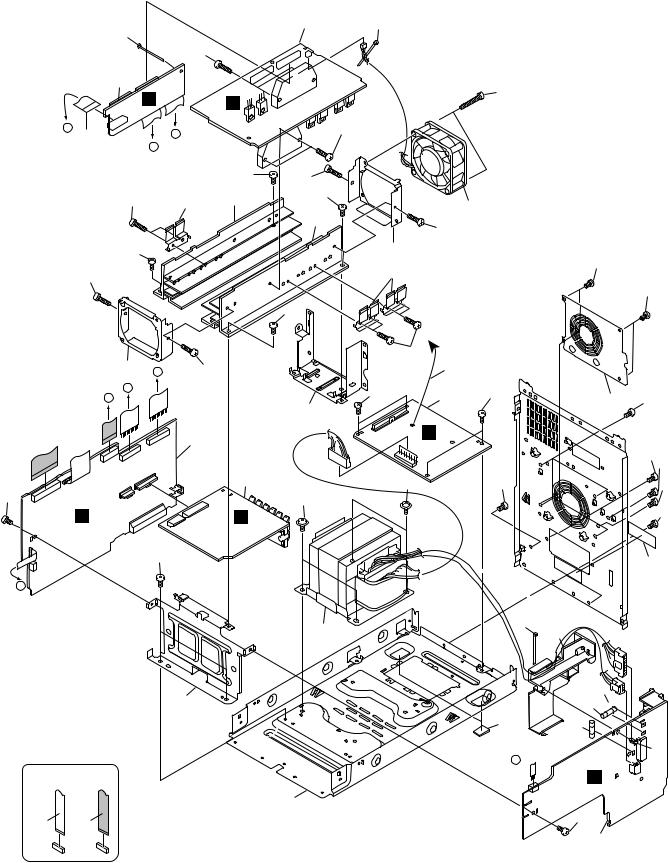
2.2 EXTERIOR SECTION
A
45
B
34
C
D
E
F
27 |
32 |
|
|
|
XV-EV61 |
|
43 |
|
3 |
|
|
|
17 |
|
|||
|
|
|
|
|
||||
|
|
5 |
|
Only |
46 |
40 |
||
|
48 |
|
|
|||||
|
|
|
|
|||||
|
|
|
|
|
||||
|
D |
|
|
|
46 |
|
|
32 |
|
C |
|
|
|
|
31 |
||
|
|
|
|
|
|
|||
|
|
C |
F |
|
|
|
|
|
|
|
12 |
|
K |
8 |
|
|
|
|
|
|
|
|
|
32 |
||
|
|
M |
|
|
|
|
|
|
|
15 |
|
|
|
|
|
|
|
|
45 |
A |
|
|
|
|
32 |
|
|
|
|
|
|
|
|
|
|
|
32 |
|
|
E |
|
|
|
|
|
9 |
L |
|
|
2 |
|
||
|
|
|
|
|
|
|
||
|
|
|
|
11 |
|
|
10 |
|
|
|
|
|
|
|
|
|
|
|
32 |
|
|
|
|
|
|
47 |
To Cassete
Deck
B
32
14
34 |
21 |
|
|
from |
D |
Secondary |
|
Assy |
25
32
|
|
|
Refer to |
|
22 |
|
|
|
|
|
|
33 |
|
|
"2.4 LOADING MECHA. ASSY". |
|
|
|
|
|
|
||
6 |
|
|
|
|
|
|
|
|
|
|
|
|
|
|
|
|
|
|
|
|
J |
|
|
|
|
|
|
|
13 |
|
|
I |
|
|
|
|
|
|
|
|
|
|
|
|
|
|
|
|
|
|
|
H |
|
|
|
|
|
|
24 |
|
|
|
|
33 |
|
|
|
|
|
|
|
33 |
|
|
|
|
16 |
|
|
|
|
|
|
|
|
|
F G |
|
|
|
|
|
|
||
36 |
|
|
E |
|
|
|
|
|
|
|
|
|
|
|
|
|
|
|
|
26 |
|
|
|
|
33 |
|
37 |
|
|
|
|
46 |
|
|
|
|
|
|
|
|
|
1 |
K |
35 |
|
||
|
|
|
|
|
|
|
|
||||
|
|
|
|
|
23 |
C |
|
|
|
|
32 |
|
|
|
|
|
|
|
|
|
|
|
|
|
|
|
|
I |
Refer to |
|
|
J |
|
|
|
4 |
|
|
|
"2.4 FRONT PANEL SECTION". |
|
|
|
31 |
|||
|
|
|
|
|
|
|
|
||||
38 |
|
|
|
|
|
|
|
|
|
||
38 |
|
|
H |
|
L |
10 M |
|
|
|
|
|
|
|
|
|
|
|
|
|
||||
|
|
47 |
|
A |
|
|
|
|
|||
|
|
|
|
|
|
|
|
32 |
|||
|
|
|
|
|
|
|
|
|
|
|
|
|
B |
|
|
G |
|
12 |
|
M |
|
|
|
|
|
|
|
|
|
|
|
|
|||
|
|
|
|
|
|
|
|
|
|
|
|
|
|
|
|
F |
|
|
|
|
|
|
18 |
38 |
|
|
|
E |
|
B |
|
|
|
|
|
|
11 |
|
D |
|
|
|
|
|
|
||
|
|
|
|
14 |
|
|
|
|
|
||
|
|
|
|
|
|
|
|
|
|
||
|
|
|
|
30 |
|
|
|
|
|
|
|
|
49 |
|
|
|
|
|
|
|
|
|
|
|
29 |
|
|
|
|
|
|
|
Refer to |
|
|
|
|
|
|
|
|
|
|
|
|
|
|
|
28 |
|
|
|
|
|
|
|
"2.3 AMP SECTION". |
||
|
|
|
|
|
C |
|
|
|
|
|
|
|
|
|
|
|
|
|
|
NON-CONTACT |
|
CONTACTSIDE |
|
|
|
|
|
|
|
|
|
7 |
SIDE |
||
|
|
|
|
|
|
|
|
32 |
|
|
|
8 |
|
XV-EV61 |
|
|
1 |
2 |
|
3 |
4 |

|
|
|
|
5 |
6 |
|
EXTERIOR SECTION parts List |
|
|||||
Mark No. |
|
|
|
Description |
Part No. |
|
|
1 |
FM/AM TUNER Module |
AXQ7228 |
|||
|
2 |
IF_AF Assy |
See Contrast table (2) |
|||
|
3 |
DECK Assy |
See Contrast table (2) |
|||
|
4 |
DVDM Assy |
See Contrast table (2) |
|||
|
5 |
DSP Assy |
See Contrast table (2) |
|||
NSP |
6 |
LOADING MECHA Assy |
VWT1208 |
|||
NSP |
7 |
Earth Lead Wire |
DE007VF0 |
|||
NSP |
8 |
Earth Lead Wire |
DE015VF0 |
|||
|
9 |
11P Flat Flexible Cable |
XDD3142 |
|||
|
10 |
13P Flat Flexible Cable |
XDD3140 |
|||
|
11 |
30P Flat Flexible Cable |
XDD3137 |
|||
|
12 |
30P Flat Flexible Cable |
XDD3143 |
|||
NSP 13 |
DVD ASSY |
See Contrast table (2) |
||||
|
14 |
12P Flat Flexible Cable |
XDD3141 |
|||
NSP 15 |
Laser Caution Label |
VRW1699 |
||||
|
16 |
Mecha Frame |
XNG3102 |
|||
|
17 |
Rear Panel A |
See Contrast table (2) |
|||
|
18 |
Rear Panel B |
See Contrast table (2) |
|||
|
19 |
• |
• |
• |
• |
|
|
20 |
• |
• |
• |
• |
|
|
21 |
DVD Shield |
XNG3103 |
|||
|
22 |
Pri Holder |
XMR3084 |
|||
|
23 |
Barrier S |
AEC7429 |
|||
|
24 |
FFC Barrier A |
XEC3048 |
|||
|
25 |
FFC Barrier B |
XEC3053 |
|||
|
7 |
8 |
Mark No. |
Description |
Part No. |
26 |
DECK PCB Holder |
XNG3115 |
27 |
Bonnet Case |
XZN3132 |
NSP 28 |
Tray Panel |
XAK3398 |
NSP 29 |
Tray Cap |
XAK3397 |
30 |
Front Panel Assy |
See Contrast table (2) |
31 |
Screw |
VPZ30P080FZK |
32 |
Screw |
BBZ30P080FZK |
33 |
Screw |
BBZ30P080FMC |
34 |
Screw |
BBZ30P080FNI |
35 |
Push Rivet |
XEC3034 |
36 |
Adaptor 02 L |
ANW7267 |
37 |
Adaptor 02 R |
ANW7268 |
38 |
Screw |
BPZ30P080FMC |
39 |
• • • • |
|
NSP 40 |
SISIR Label |
XAX3397 |
41• • • •
42• • • •
NSP 43 |
ID Label |
VXW1002 |
44 |
• • • • |
|
45 |
Screw |
BPZ30P080FNI |
46 |
Screw |
BCZ30P060FMC |
NSP 47 |
FFC Cable |
See Contrast table (2) |
48 |
Rivet |
AEC7205 |
49 |
Tray Cap Assy |
XXG3155 |
(2) CONTRAST TABLE
XV-EV61/DLXJ/NC and XV-EV31/DLXJ/NC are constructed the same except for the following :
Mark |
No |
Symbol and Description |
XV-EV61/ |
XV-EV31/ |
|
DLXJ/NC |
DLXJ/NC |
||||
|
|
|
|||
|
|
|
|
|
|
|
2 |
IF_AF Assy |
XWZ3726 |
XWZ3733 |
|
|
3 |
DECK Assy |
XWX3072 |
XWX3073 |
|
|
4 |
DVDM Assy |
AXM7808 |
AXM7809 |
|
|
5 |
DSP Assy |
AWX8254 |
Not used |
|
NSP |
13 |
DVD Assy |
AXA7121 |
AXA7122 |
|
|
17 |
Rear Panel A |
XNC3205 |
XNC3226 |
|
|
18 |
Rear Panel B |
XNC3206 |
XNC3233 |
|
|
30 |
Front Panel Assy |
XXG3156 |
XXG3158 |
|
NSP |
47 |
FFC Cable |
XDD3138 |
XDD3139 |
A
B
C
D
E
F
|
|
|
|
|
|
|
|
|
XV-EV61 |
7 |
9 |
||
5 |
6 |
|
|
|
8 |
|
1 |
2 |
3 |
4 |
2.3 AMP SECTION
A
26 |
|
|
|
35 |
|
2 |
|
|
L |
|
M |
B |
D |
|
7 |
|
|
C |
|
|
B |
|
27 |
35 |
31 |
32 |
27
35
C
|
33 |
D |
35 |
|
|
||
|
C |
|
|
|
B |
|
|
|
|
|
1 |
|
|
|
4 |
|
27 |
|
|
D |
K |
|
N |
27
A
3 |
26 |
36
35
35
27
34
32
35
33
31
27
|
To IF/AF Assy |
|
35 |
|
|
|
40 |
|
27 |
5 |
27 |
39 |
|
|
|
|
|
|
Q |
|
29 |
|
38 |
29
26
11
E
16
19
A 
CONTACT-NON SIDE |
CONTACTSIDE |
13 |
|
|
F
23
23
2127
28
27
28
27
41
 14
14
22
9
10 
10
18
P
36
6
10 |
|
XV-EV61 |
|
|
1 |
2 |
|
3 |
4 |
|
|
5 |
6 |
AMP SECTION parts List |
|
||
Mark No. |
Description |
Part No. |
|
|
1 |
E-VOL Assy |
See Contrast table (2) |
|
2 |
TRADE Assy |
See Contrast table (2) |
|
3 |
AMP Assy |
See Contrast table (2) |
|
4 |
SP-TERMINAL Assy |
See Contrast table (2) |
|
5 |
SECONDARY Assy |
See Contrast table (2) |
|
6 |
PRIMARY Assy |
XWZ3738 |
|
7 |
16P F. F. C./30V |
XDD3144 |
|
8 |
13P Jumper Connector |
52151-1310 |
> |
9 |
Fuse (FU1 : T5A) |
REK1029 |
> 10 |
Fuse (FU2, FU3 : T2.5A) |
See Contrast table (2) |
|
> |
11 |
Power Transformer (T1) |
See Contrast table (2) |
|
12 |
14P Jumper Connector |
52151-1410 |
NSP 13 |
Chassis |
XNA3016 |
|
|
14 |
Rear Panel B |
See Contrast table (2) |
|
15 |
• • • • • • • • |
|
|
16 |
Module Holder F |
XNG3112 |
|
17 |
4P Jumper Connector |
52151-0410 |
|
18 |
Push Rivet |
AEC7120 |
|
19 |
Leg Cushion |
XEB3028 |
|
20 |
• • • • • • • • |
|
|
21 |
FAN Barrier |
XEC3050 |
|
22 |
Primary Holder |
XMR3084 |
|
23 |
Push Rivet |
XEC3034 |
|
24 |
• • • • • • • • |
|
|
7 |
8 |
Mark No. |
Description |
Part No. |
25 |
• • • • • • • • |
A |
|
|
|
26 |
Binder |
ZCA-SKB90BK |
27 |
Screw |
BBZ30P080FZK |
28 |
Screw |
VPZ30P080FZK |
29 |
Screw |
ASZ40P060FMC |
30 |
FAN Holder |
ANG7417 |
31 |
FET Bracket A |
ANG7418 |
32 |
Heat Sink |
ANH7159 |
33 |
FAN Plate |
ANG7462 |
34 |
DC FAN Motor |
AXM7025 |
35 |
Screw |
B |
BBZ30P140FMC |
||
36 |
Screw |
BBZ30P300FZK |
37 |
• • • • • • • • |
|
38 |
Screw |
BCZ30P060FMC |
39 |
Module Holder R |
XNG3113 |
40 |
J1 Wire Cable |
XDX3065 |
41 |
Speaker Label |
See Contrast table (2) |
C
(2) CONTRAST TABLE
XV-EV61/DLXJ/NC and XV-EV31/DLXJ/NC are constructed the same except for the following :
Mark |
No |
Symbol and Description |
XV-EV61 |
XV-EV31 |
|
/DLXJ/NC |
/DLXJ/NC |
||||
|
|
|
|||
|
|
|
|
|
|
|
1 |
E-VOL Assy |
XWZ3736 |
XWZ3741 |
|
|
2 |
TRADE Assy |
XWZ3740 |
XWZ3745 |
|
|
3 |
AMP Assy |
AWM7720 |
AWM7787 |
|
|
4 |
SP-TERMINAL Assy |
XWZ3737 |
XWZ3742 |
|
|
5 |
SECONDARY Assy |
XWZ3739 |
XWZ3743 |
|
> |
10 |
Fuse (FU2, FU3) |
AEK1058 |
AEK1059 |
|
|
|
|
(2.5A/250V) |
(3.15A/250V) |
|
> |
11 |
Power Transformer (T1) |
XTS3070 |
XTS3071 |
|
|
14 |
Rear Panel A |
XNC3205 |
XNC3226 |
|
|
41 |
Speaker Label |
XAX3401 |
Not used |
|
|
|
|
|
|
D
E
F
|
|
|
|
|
|
|
|
|
XV-EV61 |
7 |
11 |
||
5 |
6 |
|
|
|
8 |
|
1 |
2 |
3 |
4 |
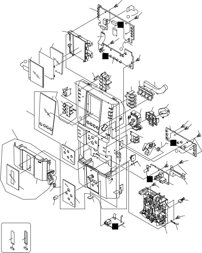
2.4 FRONT PANEL SECTION
A
33
1
33
A 
I
9
8 |
33 |
B |
13 |
11
7
6
B
33
H
|
A |
|
|
|
|
|
|
|
|
|
2 |
|
|
|
|
|
|
|
16 |
|
|
|
|
|
|
|
21 |
|
|
|
|
|
|
30 |
|
26 |
17 |
|
|
|
|
|
22 |
|
|
|
|
|
|
15 |
|
|
|
|
|
|
|
|
|
|
|
|
|
C |
|
12 |
|
|
|
|
|
|
|
24 |
|
|
|
27 |
|
|
|
|
|
|
29 |
|
|
|
|
|
|
23 |
|
|
|
|
36 |
|
|
|
|
|
|
|
|
|
|
|
|
|
|
|
|
|
|
|
|
|
33 |
|
|
|
|
|
|
3 |
33 |
|
43 |
|
|
|
|
33 |
|
|
|
|
|
|
|
||
|
|
14 |
|
25 |
18 19 |
|
|
|
|
|
|
G |
|
||
D |
|
|
|
|
17 |
|
|
|
|
|
|
|
|
||
|
|
|
|
|
B |
|
|
|
|
|
|
|
|
|
|
|
|
|
|
|
|
33 |
33 |
|
|
|
|
|
|
|
|
|
|
|
|
31 41 |
|
|
|
|
|
|
|
|
J |
|
|
|
|
34 |
|
|
33 |
5 |
40 |
|
|
|
|
|
|
|
|
|
37 |
38 |
|
|
|
|
|
|
|
|
|
|
|
|
|
E |
|
|
32 |
|
|
|
42 |
|
|
20 |
|
|
|
||
|
|
|
|
|
|
||
|
|
10 |
|
|
|
|
|
|
|
|
|
|
|
|
33 |
CONTACT-NON SIDE |
SIDECONTACT |
|
O |
4 |
|
|
|
|
|
|
|
|
39 |
||
|
|
|
|
|
|
|
|
|
|
|
|
|
|
35 |
|
F
12 |
|
XV-EV61 |
|
|
1 |
2 |
|
3 |
4 |

5 6 7 8
FRONT PANEL SECTION parts List
Mark No. |
Description |
Part No. |
Mark No. |
Description |
Part No. |
1 |
DISP 1 Assy |
XWZ3727 |
23 |
VOL. Button Assy |
XXG3159 |
2 |
DISP 2 Assy |
XWZ3728 |
24 |
Dolby Button L |
XAD3167 |
3 |
DISP 3 Assy |
XWZ3729 |
25 |
Dolby Button R |
XAD3168 |
4 |
H.P Assy |
XWZ3731 |
|
|
|
5 |
MIC Assy |
See Contrast table (2) |
26 |
FUNC. Button |
XAD3169 |
|
|
|
27 |
Play LT Cond |
XAK3402 |
6 |
4P Jumper Connector |
D20PYY0420E |
28 |
• • • • |
|
7 |
LCD |
XAV3017 |
29 |
Play Button |
XAD3171 |
8 |
8P Jumper Connector |
D20PYY0805E |
NSP 30 |
Front Panel |
See Contrast table (2) |
9 |
LCD Holder |
XMR3074 |
|
|
|
10 |
MIC Knob |
XAA3024 |
31 |
Damper Assy |
AXA7052 |
|
|
|
32 |
Leg Cushion |
XEB3028 |
11 |
Diffusion Sheet |
XAK3400 |
33 |
Screw |
VPZ30P080FZK |
NSP 12 |
Display Window |
XAK3392 |
NSP 34 |
DECK Door |
XAN3052 |
13 |
LCD LT Cond |
XAK3399 |
35 |
DECK Mechanism Unit |
XYM3016 |
NSP 14 |
Grille Panel A |
See Contrast table (2) |
|
|
|
15 |
Sensor Cover |
XAK3396 |
36 |
Front Panel Assy |
See Contrast table (2) |
|
|
|
NSP 37 |
DECK Panel |
XAK3394 |
16 |
Timer Lens |
XAK3403 |
38 |
Door Spring R |
XBH3002 |
17 |
FUNC. LT Cond |
XAK3401 |
39 |
Earth Led Wire |
DE007VEO |
18 |
Ratch Mold R |
XMR3002 |
40 |
GND Plate |
XNG3104 |
19 |
Ratch Spring R |
ABH7131 |
|
|
|
NSP 20 |
Grille Panel B |
XAK3395 |
41 |
Binder |
ZCA-SKB90BK |
|
|
|
42 |
DECK Shield Wire |
XDE3062 |
21 |
Display Button L |
XAD3165 |
43 |
DECK Door Assy |
XZN3136 |
22 |
Display Button R |
XAD3166 |
|
|
|
(2) CONTRAST TABLE
XV-EV61/DLXJ/NC and XV-EV31/DLXJ/NC are constructed the same except for the following :
Mark |
No. |
Symbol and Description |
XV-EV61/DLXJ/NC |
XV-EV31/DLXJ/NC |
|
|
|
|
|
|
5 |
MIC Assy |
XWZ3730 |
XWZ3734 |
|
14 |
Grille Panel A |
XAK3393 |
XAK3420 |
NSP |
30 |
Front Panel |
XMB3123 |
XMB3125 |
|
36 |
Front Panel ASSY |
XZN3134 |
XZN3135 |
|
|
|
|
|
A
B
C
D
E
F
|
|
|
|
|
|
|
|
|
XV-EV61 |
7 |
13 |
||
5 |
6 |
|
|
|
8 |
|
1 |
2 |
3 |
4 |
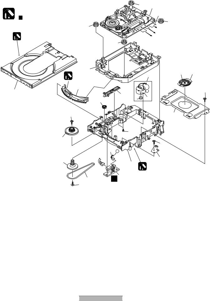
2.5 LOADING MECHANISM ASSY
A |
Note: |
|
|
|
|
|
" |
Application of Lubricant" |
|
|
8 |
|
|
Daifree |
|
|
GEM1036 |
|
|
8 |
B |
|
|
|
|
12 |
|
|
Lubricating Oil |
|
|
GYA1001 |
|
23 |
13 |
|
|
|
|
|
17 |
|
|
16 |
C |
|
22 |
15
|
|
|
|
7 |
A |
|
|
|
|
|
|
|
|
|
14 |
|
|
D |
|
|
|
|
|
|
|
|
9 |
|
A 1 |
|
|
|
22 |
|
|
|
LOADING MECHANISM ASSY parts List |
|
|
||
|
Mark No. |
Description |
Part No. |
|
Mark No. |
|
NSP 1 |
LOAB Assy |
VWG2346 |
|
16 |
|
2 |
Traverse Mechanism Assy-S |
VXX2871 |
|
17 |
|
3 |
Loading Motor Assy |
VXX2872 |
|
18 |
E |
4 |
Motor Pulley |
PNW1634 |
|
19 |
5 |
Carriage DC Motor / 0.3W |
VXM1105 |
|
20 |
|
|
|
||||
|
6 |
Flexible Cable (26P) |
VDA1944 |
|
21 |
|
7 |
Connector Assy 2P |
VKP2286 |
|
22 |
|
8 |
Float Rubber |
VEB1351 |
|
23 |
|
9 |
Belt |
VEB1330 |
|
|
|
10 |
Stabilizer |
VNE2253 |
|
|
|
11 |
Loading Base |
VNL1917 |
|
|
|
12 |
Float Base DVD |
VNL1918 |
|
|
F |
13 |
Drive Cam |
VNL1919 |
|
|
14 |
Gear Pulley |
VNL1921 |
|
|
|
|
|
|
|||
|
15 |
Loading Gear |
VNL1922 |
|
|
|
14 |
1 |
2 |
XV-EV61 |
|
|
|
|
|
||
8 |
2 |
Refer to |
|
"2.7 TRAVERSE MECHA. ASSY-S".
6
8
To DVDM CN101 (Pickup Assy-S)
To DVDM CN104 (Stepping Motor)
To DVDM CN105 (Spindle Motor)
18 20
3
A |
22 |
|
4 5
19
21
22
10
11
Lubricating Oil GYA1001
Description |
Part No. |
Drive Gear |
VNL1923 |
SW Lever |
VNL1925 |
Clamper Plate |
VNE2251 |
Bridge |
VNE2252 |
Clamper |
VNL1924 |
Screw |
JGZ17P028FMC |
Screw |
Z39-019 |
Tray |
VNL1920 |
3 |
4 |

5 |
|
6 |
7 |
8 |
|
Application of Lubricant |
|
|
|
|
|
|
|
|
Lubricating Oil |
|
A |
|
|
|
GYA1001 |
|
|
|
|
|
Around the shaft |
|
|
|
No. 11 |
|
|
|
|
|
Loading Base |
|
|
|
|
|
|
|
|
|
B |
|
|
|
Lubricating Oil |
|
|
|
|
|
GYA1001 |
|
|
|
|
|
Lubricating Oil |
Lubricating Oil |
|
Lubricating Oil |
No. 13 |
|
GYA1001 |
GYA1001 |
|
|
Inner side of a ditch |
Inner side of a ditch |
C |
||
Drive Cam |
|
||||
GYA1001 |
|
||||
|
|
|
|
|
|
Lubricating Oil |
|
Lubricating Oil |
|
No. 13 |
|
GYA1001 |
|
GYA1001 |
|
|
|
|
|
Drive cam |
|
||
|
|
|
|
|
|
Front View |
|
|
Rear View |
|
|
|
|
|
|
|
D |
|
Daifree |
|
No. 23 |
Daifree |
|
No. 23 |
|
GEM1036 |
|
||
GEM1036 |
|
|
|||
Tray |
|
Tray |
Concave of unevenness |
|
|
Concave of unevenness |
|
||||
|
|
|
|
||
|
|
|
Inner side of a ditch |
E |
|
|
|
|
|
||
|
|
|
|
Daifree |
|
|
|
|
|
GEM1036 |
|
Top View |
|
|
Bottom View |
Side of the rib |
|
|
Concave of unevenness |
|
|
||
|
|
|
|
||
|
Daifree |
|
Daifree |
|
|
|
|
GEM1036 |
|
||
|
GEM1036 |
|
|
||
|
|
|
F |
||
|
|
|
|
|
|
|
|
|
XV-EV61 |
|
15 |
5 |
|
6 |
7 |
8 |
|
1 |
2 |
3 |
4 |
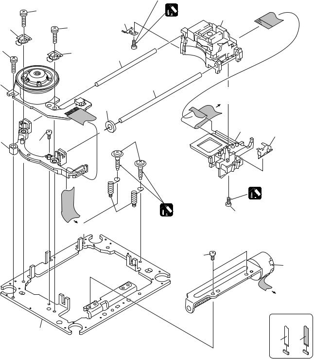
2.6 TRAVERSE MECHANISM ASSY
A
17
10
B
17
1
C
13 |
16 |
|
D
E
11
15 (Torque: 0.12 ± 0.01 N•m)
Silicone Adhesive
GEM1037
3
8
17
10
7
6
To
DVDM CN101
(Pickup Assy)
12
14
9
4 (Adjustment screw)
|
|
Silicone Adhesive |
|
|
GEM1037 |
5 |
Screw Tight |
15 (Torque: 0.12 ± 0.01 N•m) |
GYL1001 |
||
(Adjustment spring) |
|
|
To DVDM CN105 |
|
|
(Spindle Motor) |
|
|
16
2
To
DVDM CN104
(Stepping Motor)
NON-CONTACT SIDE |
CONTACT SIDE |
F
16 |
|
XV-EV61 |
|
|
1 |
2 |
|
3 |
4 |

5 6 7 8
TRAVERSE MECHANISM ASSY parts List
Mark No. |
Description |
Part No. |
1 |
Spindle Motor |
VXM1099 |
2 |
Stepping Motor |
A |
VXM1101 |
||
> 3 |
Pickup Assy-S |
OXX8005 |
4 |
Skew Screw |
VBA1080 |
5 |
Skew Spring |
VBH1335 |
6 |
Guide Bar |
VLL1514 |
7 |
Sub Guide Bar |
VLL1515 |
8 |
Leaf Spring |
VNC1023 |
9 |
Joint Spring |
VNC1019 |
10 |
Support Spring |
VNC1020 |
|
|
B |
NSP 11 |
Mechanism Chassis |
VNE2248 |
12 |
Damper Sheet |
VEB1335 |
13 |
Spacer |
VNL1913 |
14 |
Joint 03 |
VNL1949 |
15 |
Tapping Screw |
OBA8021 |
16 |
Screw |
BBZ20P050FZK |
17 |
Screw |
PMA26P100FMC |
C
D
E
F
|
|
|
|
|
|
|
|
|
XV-EV61 |
7 |
17 |
||
5 |
6 |
|
|
|
8 |
|

1 |
2 |
3 |
4 |
2.7 DECK MECHANISM ASSY
A
10
8
B
1
2
6
C
5
7
D
4
E
A
A
3
 9
9
SIDECONTACT |
CONTACT-NON SIDE |
F
18 |
|
XV-EV61 |
|
|
1 |
2 |
|
3 |
4 |

5 6 7 8
DECK MECHANISM ASSY parts List
Mark No. |
Description |
Part No. |
1 |
Main Belt |
FF19N-22 |
2 |
F/R Belt |
A |
FF19S-31 |
||
3 |
Plate HD Blk |
F513-847 |
4 |
Roller Pinch Blk R |
F514-133 |
5 |
Roller Pinch Blk L |
F514-134 |
6 |
Clutch Assy Blk |
F522-063 |
7 |
Motor Main Blk |
F525-334 |
8 |
PCB Control Blk |
F567-705 |
9 |
11P F. F. C / 30V |
XDD3142 |
10 |
18P F. F. C / 30V |
XDD3138 |
B
C
D
E
F
|
|
|
|
|
|
|
|
|
XV-EV61 |
7 |
19 |
||
5 |
6 |
|
|
|
8 |
|

1 |
2 |
3 |
4 |
3. BLOCK DIAGRAM AND SCHEMATIC DIAGRAM
3.1 OVERALL BLOCK DIAGRAM
A
3.1.1 SIGNAL ROUTE(1/2)
Refer to 3.1.2 SIGNAL ROUTE(2/2)
IC 901
B
B DVDM ASSY
IC 701
C
IC 501
D DECK ASSY
D
17 16 2
CN2506 |
RECL |
PBL |
|
E |
I DISP1 ASSY |
|
16,17
CN5801
7
61
2 
 4
4
CN5501
(REC)
2
11
E IF/AF ASSY
CN5903 VDVD
VPR
CN
CN5905 |
(D) |
|
(V)
(Y)
(C)
3 2
89
(D)
EV-61 : PDC108A
EV-31 : PDC109A
62 |
20 |
21,22 |
|
3 |
7 |
8,9 |
3 |
|
|
CN5509 |
CN5505 |
CN8003
3
IC8201
AK4114VQ
CN5101 |
IC8501 |
|
DSPD56367PV150
12 |
7 |
5,6 |
F |
DSP ASSY |
XV-EV61 Only |
F
20 |
|
XV-EV61 |
|
|
1 |
2 |
|
3 |
4 |
5 |
6 |
7 |
8 |
A
(V)JA5903
(Y)

(C)
(PB)
(TX) 
SIGNAL ROUTE
 : PB SIGNAL
 : RECORDING SIGNAL
 : AUDIO SIGNAL (TUNER)
 : V SIGNAL VIDEO
 : Y SIGNAL VIDEO : C SIGNAL VIDEO
(SL)
: SL AUDIO SIGNAL
(FL)
: FL AUDIO SIGNAL
(C)
: C AUDIO SIGNAL
(SW)
: SW AUDIO SIGNAL
(D)
: DIGITAL AUDIO ROUTE
B
J MIC ASSY
(PB) |
JA5401 |
CN5401
CN3002
(PB)
(PB)
C
(REC)
|
CN5105 |
|
O H.P ASSY |
IC8301 |
JA3901 |
CN5506 |
J3902 |
(TX) |
|
CN5701
D
CN8303
C
M 6ch AMP ASSY
FM/AM TUNER |
CN3008 |
|
MODULE |
HP |
|
AMP |
||
CN5506 |
AK4529VQ
CN8007
E
IC3401
STK402-270
BD3814FV
CN3011 CN3002
K EVOL ASSY
FL OUT
|
|
SW OUT |
N |
SP-TERMINAL |
|
|
|
|
|
ASSY |
|
|
|
|
|
|
F |
|
CN3007 |
CN3012 |
CN3307 |
CN3305 |
|
|
|
|
SL |
|
|
|
|
|
C |
|
|
|
|
|
SW |
|
|
|
|
|
FL |
|
|
|
|
XV-EV61 |
7 |
|
21 |
5 |
6 |
|
|
8 |
|

1 |
2 |
3 |
4 |
3.2 DVD SECTION BLOCK DIAGRAM
A
3.1.2 SIGNAL ROUT(2/2)
|
|
|
|
B DVDM ASSY |
|
|
|
|
|
|
|
|
|
||||
|
|
|
|
|
|
|
|
|
|
|
|
|
|
IC603 |
IC602 |
|
|
|
|
|
|
|
|
|
|
|
|
X301 |
|
|
|
VYW2077 |
K4S641632F-TC75 |
|
|
|
|
|
|
|
|
|
|
|
|
|
|
|
FLASH ROM |
64M SDRAM |
|
|
|
|
|
|
|
|
|
|
|
|
20MHz |
|
|
|
|
||||
B |
|
|
|
|
|
|
|
|
|
|
|
|
|
|
|||
CN1013 |
|
CN101 |
|
|
|
|
|
|
|
|
|
|
|
|
|
||
OEIC |
|
|
|
|
|
|
|
|
|
|
|
|
|
|
|||
SPINDLE |
|
(24P) |
|
(24P) |
|
|
|
87 |
|
|
86 |
|
|
|
|
|
|
|
|
LD(650) |
|
Q201,Q202 |
|
|
|
|
|
|
|
|
|
|
|||
MOTOR |
|
7 |
18 |
89 LD1 |
FREIN |
FREOUT |
|
|
|
CV_OUT 34 |
V |
V |
|||||
|
|
|
LD(780) |
|
|
|
|
|
|
|
|
|
|
|
|||
|
|
9 |
16 |
|
90 LD2 |
|
|
|
|
|
|
|
|
|
|||
|
|
A |
Q211,Q212 |
|
|
IC301 |
|
|
|
Y_OUT 32 S_Y |
S_Y |
||||||
|
|
17 |
8 |
|
6 |
A |
STM6316ATXXA |
|
|
|
C_OUT 33 S_C |
S_C |
|||||
|
|
|
|
|
|
|
|||||||||||
|
|
C |
|
|
Front End IC |
|
|
|
|||||||||
|
|
19 |
6 |
|
8 B |
|
|
|
|
|
|
|
|
|
|
||
|
|
|
|
|
|
|
|
|
|
|
R_OUT 27 R/Cr |
R/Cr |
|||||
|
|
16 |
B1 |
9 |
|
14 C |
|
|
|
OUT_DATA |
|
16 B_DATA |
|||||
|
|
|
|
|
|
|
FE DATA |
G_OUT 26 G/Y |
G/Y |
||||||||
|
|
15 |
B2 |
10 |
|
12 D |
|
|
|
|
64 |
||||||
|
|
|
|
|
|
|
|
|
|
|
B_OUT 25 B/Cb |
B/Cb |
|||||
|
|
22 |
B3 |
3 |
|
21 E |
|
|
|
|
|
|
|
||||
|
|
|
|
|
|
|
|
|
|
|
|
|
|||||
|
|
|
|
|
|
|
|
|
|
|
|
|
|
||||
|
|
21 |
B4 |
4 |
|
20 F |
PC(6) |
PD(0) |
PE(1) PC(2) |
|
|
|
|
|
|||
|
|
|
|
|
|
|
|
|
|||||||||
PICKUP |
2 |
TRKG DRV |
23 |
|
|
|
44 |
|
55 |
70 |
38 |
|
|
|
|
|
|
|
|
|
|
|
|
SPDLPDM |
|
LOADDRV |
|
|
|
|
|
|
|
||
ASSY-S |
3 |
TRKG RTN |
22 |
|
|
|
|
CLOSE |
OPEN |
|
|
|
|
|
|||
|
|
|
|
|
|
|
|
|
|
|
|
||||||
C |
|
4 |
FOCS DRV |
21 |
|
|
|
|
|
|
|
|
|
||||
|
|
1 |
FOCS RTN |
24 |
|
|
|
26 |
|
40 |
|
|
|
|
|
|
|
|
|
|
|
|
|
|
|
|
|
|
|
|
|
|
|
||
|
|
|
|
|
|
30 |
TO- |
SPIN LOIN+ |
|
|
|
|
|
|
|
|
|
|
|
|
|
31 |
TO+ |
IC601 |
|
|
PCMDATA0 |
|
|
A DATA0 |
|
|
|
|
|
|
CN105 |
34 |
FO- |
STM5589CVA |
|
|
|
||||
|
|
|
|
|
Back End IC |
|
|
52 |
|
|
|
||||
|
|
|
|
|
(12P) |
35 |
FO+ |
|
|
|
|
|
|
|
|
|
|
|
|
H3- |
4 |
16 |
HW- |
|
|
|
|
|
|
|
|
|
|
|
|
H3+ |
5 |
17 |
HW+ |
|
|
|
|
|
|
|
|
|
|
|
|
H2- |
6 |
18 |
HV- |
|
|
|
|
SPDIF |
|
|
DOUT |
|
|
|
|
H2+ |
7 |
19 |
HV+ |
|
|
|
|
57 |
|
|
|
|
|
|
|
|
|
|
|
|
|
|
|
||||
|
|
|
|
H1- |
8 |
20 |
HU- |
|
|
|
|
|
|
|
|
|
|
|
|
H1+ |
9 |
21 |
HU+ |
IC101 |
|
|
|
|
|
|
|
|
|
|
|
|
|
|
M63018FP |
|
|
|
|
|
|
|
|
|
|
|
|
|
CN104 |
|
FTS Driver |
|
|
|
|
|
|
|
|
D |
STEPPING |
M |
ST2- |
4 |
6 |
SL2- |
|
|
|
|
|
|
|
|
|
|
|
|
|
|
|
|
|
|
|||||||
|
MOTOR |
ST2+ |
3 |
5 SL2+ |
|
|
|
|
|
|
|
|
|||
|
|
|
|
|
|
|
|
|
|
||||||
|
|
|
|
ST1+ |
2 |
9 |
SL1+ |
|
|
|
|
|
|
|
|
|
|
|
|
ST1- |
1 |
10 |
SL1- |
PIXCLK |
|
|
|
|
|
|
|
|
|
|
|
|
120 |
|
|
|
|
|
|
|
|||
|
|
|
|
|
|
|
|
|
|
|
|
|
|
|
|
|
CN602 |
CN601 |
|
CN103 |
|
|
IC604 TC7WU04FU |
|
|
|
|||||
|
2 |
|
1 |
LOAD- |
1 |
36 |
LO+ |
|
|
|
|||||
|
|
(3/3) |
|
(2/3) |
|
|
|
|
|||||||
|
|
|
|
|
|
|
|
||||||||
|
– M + 1 |
|
2 LOAD+ |
2 |
37 |
|
|
|
|
|
|
||||
|
|
LO- |
5 |
3 |
2 |
6 |
|
|
|
|
|||||
|
LOADING |
|
|
|
|
|
|
|
|
|
|
|
|
|
|
|
MOTOR |
|
3 |
SW2 |
3 |
CLOSE |
|
|
|
|
|
|
|
|
|
|
ASSY |
|
V+3D |
|
|
|
|
|
X601 |
|
|
|
|
||
|
S101 |
|
4 |
4 |
|
|
|
|
27MHz |
|
|
|
|
||
|
|
|
OPEN |
|
|
|
|
|
|
|
|||||
|
|
|
5 |
SW1 |
5 |
|
|
|
|
|
|
|
|
|
|
|
|
|
|
|
|
|
|
|
|
|
|
|
|
||
|
A LOAB ASSY |
V+3R3_FED |
|
|
IC411 |
|
|
|
|
||||||
|
|
V+1R8_FED V+1R8_FEA PQ018EZ01ZP |
V+3R3_FEA V+3R3_FED |
V+3R3 |
|||||||||||
E |
|
|
|
||||||||||||
|
|
|
|
1.8V Reg. |
|
|
|
|
|||||||
|
|
|
|
|
|
|
|
|
|
|
|
|
|||
|
|
|
|
|
|
|
|
|
3 |
|
1 |
|
|
|
|
|
|
|
|
|
|
|
|
|
|
|
|
IC421 |
|
|
|
|
|
|
|
|
|
|
|
|
V+1R8_BE |
PQ018EH01ZP |
V+3D |
|
|||
|
|
|
|
|
|
|
|
|
|
|
|
1.8V Reg. |
|
|
|
|
|
|
|
|
|
|
|
|
|
|
|
3 |
1 |
|
|
F
22 |
|
XV-EV61 |
|
|
1 |
2 |
|
3 |
4 |

5 |
6 |
7 |
8 |
A
|
|
|
IC501 |
|
|
|
EV61 Only |
B |
|
|
|
|
MM1623AF |
|
CN923 |
|
|
||
|
|
Video Driver Amp. |
|
|
|
|
|||
|
|
|
(18P) |
|
|
|
|||
V |
V |
4 |
V IN |
V OUT 23 |
V |
16 |
V |
|
|
S_Y |
S_Y |
6 Y IN |
Y OUT |
S_Y |
18 S_Y |
|
|
||
21 |
|
|
|||||||
S_C |
S_C |
2 |
C IN |
C OUT 26 S_C |
14 |
S_C |
E CN5905 |
|
|
R/Cr |
R/Cr |
14 |
Cr IN |
Cr OUT |
R/Cr |
12 |
R/Cr |
|
|
|
|
|
16 |
|
|
|
|||
G/Y |
G/Y |
10 CY IN |
CY OUT 20 |
G/Y |
8 |
G/Y |
|
|
|
B/Cb |
B/Cb |
12 Cb IN |
Cb OUT 18 B/Cb |
10 |
B/Cb |
|
|
||
|
|
|
3 13 |
|
|
|
|
|
|
|
|
MUTE1 |
MUTE2 |
|
CN902 |
|
EV31 Only |
|
|
|
|
|
|
|
|
(11P) |
|
|
|
|
|
|
|
|
|
|
|
|
|
|
|
|
|
|
|
4 |
V |
|
|
|
|
|
|
|
|
6 |
C |
|
C |
|
|
IC701 |
|
|
2 |
Y |
|
||
|
|
|
|
|
|
||||
|
|
|
|
|
E CN5904 |
|
|||
|
PCM1742KE |
|
|
|
|
||||
|
Audio 2ch DAC |
|
|
|
|
||||
|
|
|
VoutL |
7 |
|
8 |
DVDL |
|
|
A DATA0 |
2 DATA |
|
|
|
|
||||
VoutR |
|
10 |
|
|
|
||||
|
|
|
|
8 |
|
DVDR |
|
|
|
|
|
|
|
|
|
CN901 |
|
|
|
|
|
|
|
|
|
(30P) |
|
|
|
DOUT |
|
|
|
|
|
21 |
DOUT |
|
|
|
|
|
|
|
|
|
|
|
|
|
|
|
|
|
|
17 |
XDVDRST |
|
|
|
|
|
|
|
|
|
|
|
|
|
|
IC911 |
|
|
16 |
SYS_CS1 |
|
|
|
|
TC74VHC08FT |
|
|
|
|
||||
|
|
|
SYS_CS2 |
|
|
||||
|
5V |
→ 3V Converter |
|
15 |
|
|
|||
|
|
|
|
|
|
|
|
|
|
|
|
|
|
|
|
13 |
SDATA |
|
D |
|
|
IC901 |
|
|
|
|
|||
|
|
|
|
|
SCLK |
|
|||
|
TC74VHC125AFT |
|
14 |
|
|
||||
|
|
|
|
|
|||||
|
3V |
→ 5V Converter |
|
12 |
MDATA |
|
|
||
|
|
|
|
|
|
|
|
|
|
|
|
|
|
|
|
11 |
ACK |
|
|
|
|
|
|
|
|
|
|
|
|
|
|
|
|
|
|
7 |
DVDTRKUP |
|
|
|
|
|
|
|
|
|
|
|
|
|
|
|
|
|
|
18 |
DVDPOWER |
E CN5903 |
|
|
|
|
|
|
|
8 |
VDET |
|
|
|
|
|
|
|
|
|
|
||
|
|
|
|
|
|
5 |
XVMUTE |
|
|
|
|
|
|
|
|
|
|
|
|
|
|
|
|
V+12 |
|
VDVD+12 |
|
|
|
|
|
|
|
|
Q451 |
|
VDVD+12 |
|
|
|
|
|
|
|
|
30 |
|
|
|
|
|
|
|
|
|
|
|
|
|
|
|
|
|
|
IC401 |
|
|
|
|
|
|
|
|
R1224N102H |
VPR+8 |
|
|
E |
|
|
|
|
|
3V Reg. |
|
|
|||
|
|
|
|
|
|
|
|||
3 |
6 |
29 |
VPR+8 |
|
|||
|
|
28 |
VPR+8 |
|
|
|
IC431
V+5D V+5V V+5 MM1565AF
5V Reg.
|
1 |
7 |
|
|
|
|
IC441 |
VPR+8M |
|
V+6 |
PQ20WZ11 |
|
VPR+8M |
|
|
6V Reg. |
27 |
||
|
|
|
|
|
|
3 |
1 |
26 |
VPR+8M |
|
|
|||
F
|
|
|
|
|
|
|
|
|
XV-EV61 |
7 |
23 |
||
5 |
6 |
|
|
|
8 |
|
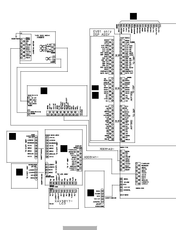
1 |
2 |
3 |
4 |
3.3 OVERALL WIRING DIAGAM
A |
|
|
|
|
|
|
3.3.1 OVERALL WIRING DIAGRAM (1/2) |
|
|
|
|
||
|
|
To-OVERALL WIRING DIAGRAM (2/2) |
K J3002 |
|||
|
|
|
|
D20PYY1520E |
|
|
DECK |
|
|
|
CN8302 |
|
|
MECHA. (XYM3016) |
|
|
|
|
||
CN8334 |
|
|
|
CN8011 |
CN5507 |
|
|
|
|
|
|
|
|
B |
CN8281 |
DSP ASSY (AWX8254 / XV-EV61) |
|
|
|
|
|
CN8280 |
|
|
|
||
|
|
|
|
|
|
|
|
|
|
2/2 |
CN8003 |
CN5505 |
|
C |
|
|
1/2 - |
|
|
|
|
|
F |
|
|
|
|
|
D |
DECK ASSY |
|
|
|
|
|
|
|
|
|
||
CN2301 |
(XWX3072/XV-EV61) |
F |
|
|
|
|
|
|
(XWX3073/XV-EV31) |
|
|
|
|
|
|
|
|
CN8007 |
CN5506 |
|
CN2302 |
CN2506 |
|
|
|
|
|
|
|
|
|
|
|
|
D |
|
|
|
|
|
|
J5102 |
CN5102 |
|
|
|
|
|
H |
|
DISP1 ASSY |
|
|
|
|
|
|
(XWZ3727) |
|
|
|
|
|
|
I |
|
|
CN5503 |
|
|
|
|
|
|
|
|
DISP2 ASSY |
|
|
|
|
|
|
(XWZ3728) |
J5103 |
|
|
|
|
|
|
|
|
|
|
||
E |
|
|
|
|
|
|
G |
|
CN5104 |
MIC ASSY |
|
|
|
|
|
(XWZ3730/ |
|
|
||
DISP3 ASSY |
|
XV-EV61) |
|
|
|
|
(XWZ3729) |
|
(XWZ3734/ |
|
CN5501 |
||
|
|
|
||||
|
|
XV-EV31) |
|
|
||
|
|
|
|
|
||
|
|
|
|
|
|
|
|
|
|
J |
|
CN5105 |
|
|
|
|
|
|
|
|
F |
|
|
|
|
|
|
24 |
|
XV-EV61 |
|
|
|
|
1 |
|
2 |
|
3 |
|
4 |

5 |
6 |
7 |
8 |
Note : When ordering service parts, be sure to refer to "EXPLODED VIEWS and PARTS LIST" or "PCB PARTS LIST"
|
|
To-OVERALL WIRING DIAGRAM (2/2) |
|
K |
CN3001 |
||
XDD3143 |
CN8303
CN201 |
|
(RF) : RF SIGNAL ROUTE |
|
CN5701 |
MODULE (AXQ7228) |
||
TUNERFM/AM |
(F) |
: FOCUS SERVO LOOP LINE |
|
|
|
||
|
|
(T) |
: TRACKING SERVO LOOP LINE |
|
|
(S) |
: STEPPING SERVO LOOP LINE |
|
C |
|
|
DVD ASSY (AXA7123)
E |
( |
E |
1/2- |
E |
2/2 |
( |
IF/AF ASSY
(XWZ3726 / XV-EV61) (XWZ3733 / XV-EV31)
CN5801
CN5502 |
CN5902 |
CN5903 |
CN901 |
|
|
B 1/3- B 3/3 ASSY (AXM7808/XV-EV61) |
|
|
B |
DVDM |
CN5905 |
CN903 |
|
|
|
|
|
|
-EV31) |
CN5904 |
CN902 |
(AXM7809/XVASSYDVDM |
|
||
PICKUP ASSY-S (OXX8005) |
||
|
(RF) |
|
|
(RF) |
|
|
(RF) |
|
|
(RF) |
|
|
(RF) |
|
|
(RF) |
|
|
(F) |
|
|
(T) |
|
|
(T) |
|
|
(F) |
|
(S) |
STEPPING |
|
MOTOR |
||
(S) |
||
: VXM1101 |
||
(S) |
||
|
||
(S) |
|
|
SPINDLE MOTOR : VXM1099
A LOAB ASSY (VWG2346)
LOADING MOTOR
ASSY : VXX2505
A
|
|
|
|
|
|
|
|
|
XV-EV61 |
7 |
25 |
||
5 |
6 |
|
|
|
8 |
|
A
B
C
D
E
F

1 |
2 |
3 |
4 |
3.3.2 OVERALL WIRING DIAGARAM (2/2)
A
B
C
D
M AMP MODULE ASSY (AWM7720 / XV-EV61) (AWM7787 / XV-EV31)
N |
SP-TERMINAL |
ASSY |
(XWZ3737 |
/XV-EV61) |
(XWZ3742 |
/XV-EV31) |
L TRADE ASSY (XWZ3740/XV-EV61) (XWZ3745/XV-EV31)
K E-VOL ASSY (XWZ3736/XV-EV61) (XWZ3741/XV-EV31)
E
E CN8302
E IF/AF ASSY
F
26 |
|
XV-EV61 |
|
|
1 |
2 |
|
3 |
4 |
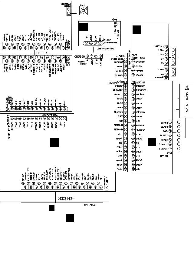
5 |
6 |
7 |
8 |
A
O |
HP ASSY |
P |
|
(XWZ3731) |
|
||
|
|
PRIMARY ASSY |
B |
|
|
(XWZ3738) |
|
|
SECONDARY ASSY (XWZ3739/XV-EV61) |
(XWZ3743/XV-EV31) |
K E-VOL ASSY |
Q |
|
(XWZ3736/XV-EV61) |
|
|
(XWZ3741/XV-EV31) |
|
|
E CN8303 |
|
|
E IF/AF ASSY |
|
|
T1
POWER
TRANSFORMER
XTS3070:XV-EV61
XTS3071:XV-EV31
C
D
E
F
|
|
|
|
|
|
|
|
|
XV-EV61 |
7 |
27 |
||
5 |
6 |
|
|
|
8 |
|

A
B
C
D
E
F
1 |
2 |
3 |
4 |
3.4 FM/AM TUNER MODULE
C FM/AM TUNER MODULE (AXQ7228)
FM FRONT END
(FM)
(FM) |
(FM) |
|
(FM)
(FM)
(FM)
(FM)
|
|
(FM) |
(FM) |
|
(AM) |
(AM) |
|
(AM) |
|
|
(AM) |
MW RF TUNING BLOCK |
|
|
(FM) |
(AM) |
|
(AM)
OSC : 981 - 2052kHz 9k step
C
28 |
|
XV-EV61 |
|
|
1 |
2 |
|
3 |
4 |
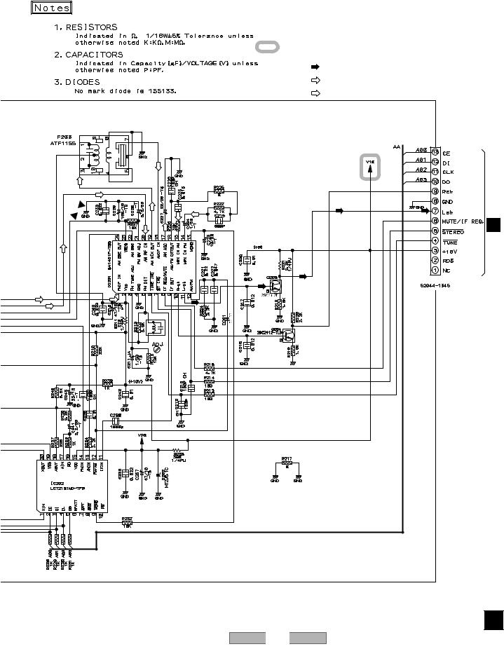
5 |
6 |
7 |
8 |
A
: The power supply is shown with the marked box.
(TX)
: AUDIO SIGNAL ROUTE (TUNER)
(AM)
: AM SIGNAL ROUTE
(FM)
: FM SIGNAL ROUTE
|
|
|
|
|
B |
|
(AM) |
|
|
|
|
(AM) |
|
|
|
|
|
(AM) |
(AM) (AM) (FM) (AM) |
(AM) |
(FM) |
(TX) |
|
|
|
||||
|
|
(TX) |
|||
|
|
C |
|||
|
|
CN5701E |
|||
(AM) |
|
|
|
|
|
|
|
|
|
(TX) |
CN201 |
|
|
|
|
(TX) |
|
(FM) |
(FM) |
|
|
|
|
(AM) |
|
(TX) |
|
|
|
|
|
|
|
|
|
|
L201 |
|
|
|
|
|
ATE7003 |
|
|
|
|
|
|
|
|
|
D |
|
|
|
|
|
E |
|
|
|
|
|
F |
|
|
|
|
|
C |
|
|
|
|
XV-EV61 |
29 |
5 |
|
|
6 |
7 |
8 |

1 2
3.5 DVDM ASSY(1/3)
A |
B 1/3 DVDM ASSY |
|
|
|
(AWM7808/XV-EV61) |
|
(AWM7809/XV-EV31) |
CN601 |
|
|
A |
|
|
B |
MOTOR |
|
STEPPING |
(S) |
|
|
|
|
|
|
(S) |
|
|
(S) |
|
|
(S) |
|
|
(S) |
|
|
|
(S) |
|
C |
MOTORSPINDLE |
(S) |
|
(S) |
|||
|
|||
|
|
D
(F)
 (T)
(T)
(T)
 (F)
(F)
|
-S |
|
E |
ASSY |
|
|
|
|
|
PICKUP |
(RF) |
|
|
|
|
|
(RF) |
|
|
(RF) |
(RF)
(RF) (RF)
F
B 1/3
30
1 |
2 |
3 |
4 |
 (F)
(F)
(F)
3 |
(T) |
|
(T) |
XV-EV61
3 |
4 |
 Loading...