


XV EV51
Table of contents
 Loading...
ORDER NO.
PIONEER CORPORATION 4-1, Meguro 1-chome, Meguro-ku, Tokyo 153-8654, Japan
PIONEER ELECTRONICS (USA) INC. P.O. Box 1760, Long Beach, CA 90801-1760, U.S.A.
PIONEER EUROPE NV Haven 1087, Keetberglaan 1, 9120 Melsele, Belgium
PIONEER ELECTRONICS ASIACENTRE PTE. LTD. 253 Alexandra Road, #04-01, Singapore 159936
PIONEER CORPORATION 2002
SOUND MODE
KARAOKE
VOLUME
ST. MEMORY
TIMER/CLOCK ADJ
DISPLAY
STEREO DVD TUNER DECK
EV51DVD
ENTER
DVD/CD
TUNER
TAPE
LINE
OPEN/CLOSE
DOLBY NR(DEMO)
ASES
MIC VOL
MAX
MIN
MIC
(MAIN)
MIC
(SUB)
REVERSE MODE
REC/STOP
PLAY/PAUSE STOPTUNING – TUNING +
4/1
¡/¢
–+
XV-EV51
RRV2636
STEREO DVD TUNER DECK
XV-EV51
XV-EV21
THIS MANUAL IS APPLICABLE TO THE FOLLOWING MODEL(S) AND TYPE(S).
This product does not function properly independently; to avoid malfunctions, be sure
to connect it to the prescribed system component(s), otherwise damage may result.
Model Type Power Requirement
Regienal restriction
codes (Region No.)
Remarks
XV-EV51 ZLXJ/NC DC Power supplied from other system component 4
XV-EV21 ZLXJ/NC DC Power supplied from other system component
4
Component System System Service manual
MINI SYSTEM EVA-5CH EVA-2CH
Stereo DVD Tuner Deck XV-EV51 XV-EV21 RRV2636(This manual)
Stereo Power Amplifier M-EV51 M-EV21 RRV2663(EV51), RRV2664(EV21)
Speaker System S-EV51V S-EV21V RRV2640(EV51), RRV2641(EV21)
For details, refer to "Important symbols for good services" .
T-ZZR AUG. 2002 printed in Japan
XV-EV51
2
1234
1234
C
D
F
A
B
E
SAFETY INFORMATION
This service manual is intended for qualified service technicians ; it is not meant for the casual do-
it-yourselfer. Qualified technicians have the necessary test equipment and tools, and have been
trained to properly and safely repair complex products such as those covered by this
manual.Improperly performed repairs can adversely affect the safety and reliability of the product
and may void the warranty. If you are not qualified to perform the repair of this product properly and
safely, you should not risk trying to do so and refer the repair to a qualified service technician.
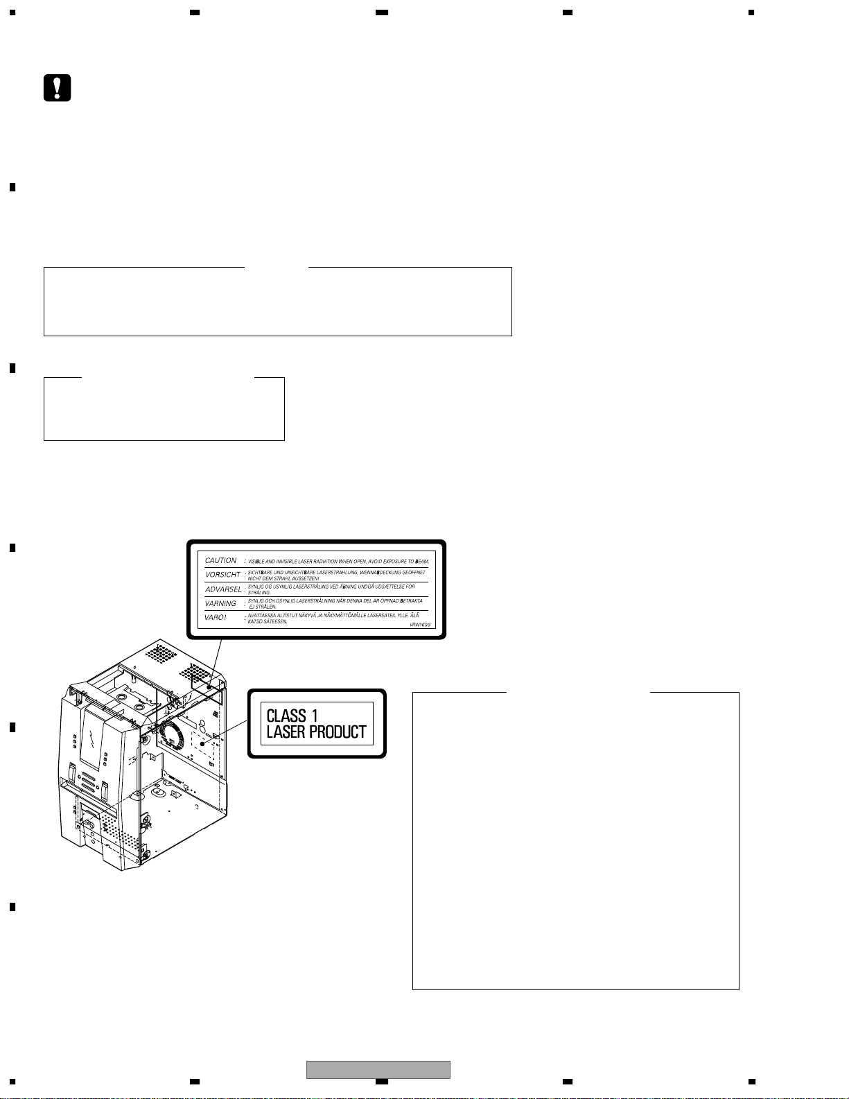
WARNING !
THE AEL (ACCESSIBLE EMISSION LEVEL) OF THE LASER POWER OUTPUT IS LESS THAN CLASS 1
BUT THE LASER COMPONENT IS CAPABLE OF EMITTING RADIATION EXCEEDING THE LIMIT FOR
CLASS 1.
A SPECIALLY INSTRUCTED PERSON SHOULD DO SERVICING OPERATION OF THE APPARATUS.
LASER DIODE CHARACTERISTICS
FOR DVD : MAXIMUM OUTPUT POWER : 5 mW
WAVELENGTH : 650 nm
FOR CD : MAXIMUM OUTPUT POWER : 5 mW
WAVELENGTH : 780 nm
Additional Laser Caution
∗ : See page 80.
1. Laser Interlock Mechanism
• Loading switch (S101 on the LOAB Assy) is used for interlock
mechanism of the laser.
When this switch turned ON in SW2 (XCLOSE) side (OPEN signal is
0V and XCLOSE signal is 3.5V), a laser becomes the status which
can completely oscillation.
Furthermore, the laser completely oscillates in the disc judgment and
disc playback.
When player is power ON state and laser diode is not completely
oscillating, 780nm laser diode is always oscillating by half power.
• Laser diode is driving with Q101 (650nm LD) and Q102 (780nm LD)
on the DVDM Assy.
Therefore, when short-circuit between the emitter and collector of
these transistors or the base voltage is supplied for transistors turn
on, the laser oscillates. (failure mode)
• In the test mode ∗ , there is the mode that the laser oscillates except
for the disc judgment and playback. LD ON mode in the test mode
oscillates with the laser forcibly.
The interlock mechanism mentioned above becomes invalid in this
mode.
2. When the cover is open, close viewing through the objective lens with
the naked eye will cause exposure to the laser beam.
LABEL CHECK
XV-EV51/ZLXJ/NC
(Printed on the Rear Panel A)
XV-EV51
3
5 678
56
7
8
C
D
F
A
B
E
[ Important symbols for good services ]
In this manual, the symbols shown-below indicate that adjustments, settings or cleaning should be made securely.
When you find the procedures bearing any of the symbols, be sure to fulfill them:
2. Adjustments
To keep the original performances of the product, optimum adjustments or specification confirmation is indispensable.
In accordance with the procedures or instructions described in this manual, adjustments should be performed.
3. Cleaning
For optical pickups, tape-deck heads, lenses and mirrors used in projection monitors, and other parts requiring cleaning,
proper cleaning should be performed to restore their performances.
5. Lubricants, glues, and replacement parts
Appropriately applying grease or glue can maintain the product performances. But improper lubrication or applying
glue may lead to failures or troubles in the product. By following the instructions in this manual, be sure to apply the
prescribed grease or glue to proper portions by the appropriate amount.For replacement parts or tools, the prescribed
ones should be used.
4. Shipping mode and shipping screws
To protect the product from damages or failures that may be caused during transit, the shipping mode should be set or
the shipping screws should be installed before shipping out in accordance with this manual, if necessary.
1. Product safety
You should conform to the regulations governing the product (safety, radio and noise, and other regulations), and
should keep the safety during servicing by following the safety instructions described in this manual.
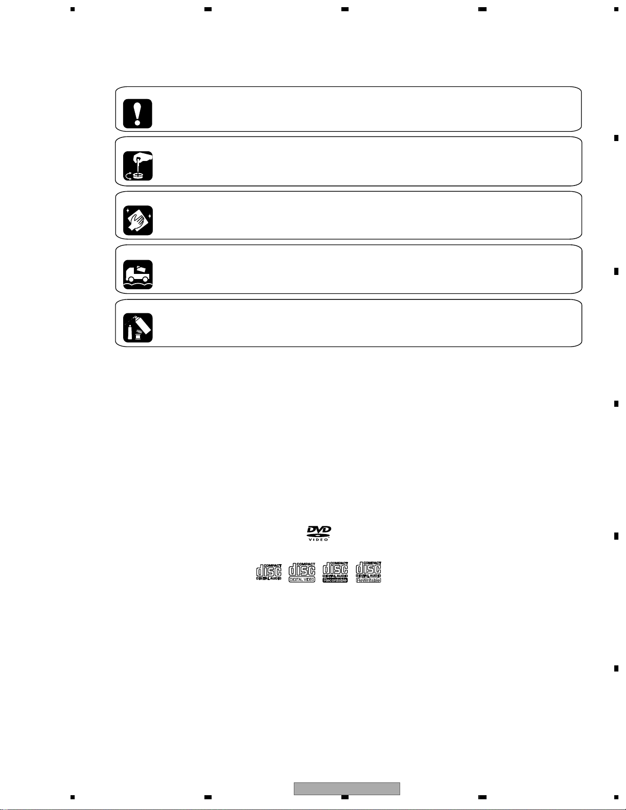
Discs compatible with this
player
Any disc that displays one of the following
logos should play in this player. Other
formats, including DVD-Audio, DVD-RAM,
DVD-ROM, CD-ROM (except those that
contain MP3 files), SACD and Photo CD will
not play.
Audio-CD
DVD-Video
Video-CD
* : Video Mode Only
CD-R * CD-RW *

XV-EV51
4
1234
1234
C
D
F
A
B
E
CONTENTS
SAFETY INFORMATION..................................................................................................................................... 2
1. SPECIFICATIONS ............................................................................................................................................ 5
2. EXPLODED VIEWS AND PARTS LIST ............................................................................................................ 6
2.1 PACKING ................................................................................................................................................... 6
2.2 EXTERIOR SECTION................................................................................................................................ 8
2.3 FRONT PANEL SECTION ....................................................................................................................... 10
2.4 LOADING MECHANISM ASSY ............................................................................................................... 12
2.5 TRAVERSE MECHANISM ASSY............................................................................................................. 14
3. BLOCK DIAGRAM AND SCHEMATIC DIAGRAM ..........................................................................................16
3.1 BLOCK DIAGRAM ................................................................................................................................... 16
3.2 OVERALL WIRING DIAGAM ................................................................................................................... 20
3.3 FM/AM TUNER MODULE........................................................................................................................ 24
3.4 IF ASSY ................................................................................................................................................... 26
3.5 AF ASSY(1/2) .......................................................................................................................................... 28
3.6 AF ASSY(2/2) .......................................................................................................................................... 30
3.7 DECK ASSY ............................................................................................................................................ 32
3.8 DVDM ASSY(1/2)..................................................................................................................................... 34
3.9 DVDM ASSY(2/2)..................................................................................................................................... 36
3.10 DVD IF ASSY......................................................................................................................................... 38
3.11 DISP1, DISP2, DISP3 and LED ASSYS................................................................................................ 40
3.12 DSP ASSY ............................................................................................................................................. 42
3.13 MIC ASSY.............................................................................................................................................. 44
4. PCB CONNECTION DIAGRAM ..................................................................................................................... 46
4.1 LOAB ASSY............................................................................................................................................. 46
4.2 FM/AM TUNER MODULE........................................................................................................................ 47
4.3 DVDM ASSY............................................................................................................................................ 48
4.4 DVD IF ASSY........................................................................................................................................... 52
4.5 IF ASSY ................................................................................................................................................... 54
4.6 AF ASSY.................................................................................................................................................. 56
4.7 DECK ASSY ............................................................................................................................................ 58
4.8 DISP1, DISP2, DISP3 and LED ASSYS.................................................................................................. 60
4.9 MIC ASSY................................................................................................................................................ 62
4.10 DSP ASSY(XV-EV51 Only) .................................................................................................................... 63
5. PCB PARTS LIST ........................................................................................................................................... 64
6. ADJUSTMENT ............................................................................................................................................... 72
6.1 DECK SECTION ...................................................................................................................................... 72
6.1.1 Adjustment condition ......................................................................................................................... 72
6.1.2 Playback and Recording section ....................................................................................................... 73
6.2 TUNER SECTION .................................................................................................................................... 75
6.3 DVD SECTION ADJUSTMENT ITEMS ana LOCATION.......................................................................... 76
6.4 JIGS and MEASURING INSTRUMENTS ................................................................................................ 76
6.5 NECESSARY ADJUSTMENT POINTS ................................................................................................... 77
6.6 TEST MODE ............................................................................................................................................ 78
6.7 MECHANISM ADJUSTMENT.................................................................................................................. 79
7. GENERAL INFORMATION ............................................................................................................................. 82
7.1 DIAGNOSIS ............................................................................................................................................. 82
7.2 PARTS.................................................................................................................................................... 101
7.3 CLEANING............................................................................................................................................. 120
8. PANEL FACILITIES ...................................................................................................................................... 121
XV-EV51
5
5 678
56
7
8
C
D
F
A
B
E
1. SPECIFICATIONS
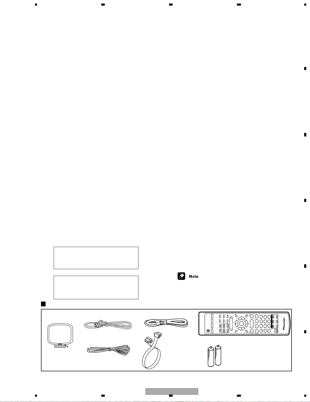
Accessories
(XXD3049)
AM loop antenna
(ATB7009)
FM wire antenna
AC Power Cord
(ADH7004)
(XDG3001)
AA size IEC R6P
Dry cell batteries (x2)
Specifications
Amplifier Section
X-EV51DVD model
Continuous Power Output:
Front
...................................
80 W per channel
(1kHz, 10 %, 8 Ω)
Center
......................
33 W (1kHz, 10 %, 8 Ω)
Surround
.............................
33 W per channel
(1kHz, 10 %, 8 Ω)
X-EV21DVD model
Continuous Power (RMS)
.............
80 W + 80 W
(1 kHz, THD 10%, 8 Ω)
Disc section
Digital audio
characteristics
................
DVD fs: 96 kHz, 24-bit
Type
...........
DVD system, Video CD system and
Compact Disc digital audio system
Frequency response
...................
4 Hz to 44 kHz
S/N ratio
....................................................
95 dB
Dynamic range
.........................................
95 dB
Total harmonic distortion
.....................
0.005 %
Wow and Flutter..................Limit of measurement
( 0.001 % W.PEAK) or less (EIAJ)
Cassette deck section
Systems
.........................
4 track, 2-channel stereo
Heads.......................Recording/playback head x 1
Erasing head x 1
Motor
...................................
DC servo motor x 1
Tape types
...............................
TYPE I (Normal)
FM tuner section
Frequency Range
........................
87.5 - 108MHz
Antenna
..................................
75 Ω, unbalanced
AM tuner section
FrequencyRange
With 9 kHz step
..........
531 kHz to 1,602 kHz
With 10 kHz step
........
530 kHz to 1,700 kHz
Antenna
........................................
Loop antenna
Manufactured under license from Dolby
Laboratories. “Dolby”, “Pro Logic”, and
the
double-D symbol are trademarks of Dolby
Laboratories.
"DTS" and "DTS Digital Surround" are registered
trademarks of Digital Theater Systems, Inc.
Manufactured under license from Digital Theater
Sy
±
stems, Inc.
Miscellaneous
Power Requirements
Multi voltage model .......
.......
AC 110-127/ 220-230/
Power Consumption
X-EV51DVD model
Singapore, Malaysia, Hong Kong models
....................................
....................................
175 W
All other model 465 W
X-EV21DVD model
Singapore, Malaysia models .................. 150 W
All other model 540 W
Power Consumption in standby mode .............1 W
Dimensions:
DVD Tuner Deck .................. 170 (W) x 292.5 (H)
x 260 (D) mm
Power Amplifier
....................... 170 (W) x 190 (H)
x 254 (D) mm
Weight:
DVD Tuner Deck
XV-EV51 ................................................ 3.6 kg
XV-EV21 ................................................ 3.5 kg
Power Amplifier
M-EV51 .................................................. 5.3 kg
M-EV21 .................................................. 4.8 kg
Accessories (Stereo DVD Tuner Deck)
Operating instructions..........................................2
•
Specifications and design subject to
possible modification without notice,
due to improvements.
Accessories (Stereo Power Amplifier)
Remote control .................................................... 1
Power cord
Australian, New Zealand, Central
and South American models........................... 2
All other models ............................................. 1
Power plug adapter (excluding Singapore,
Hong Kong and Malaysian models)..................... 1
Video cord............................................................ 1
System cable (EV51DVD) ................................... 2
System cable (EV21DVD) ................................... 1
FM antenna.......................................................... 1
AM loop antenna.................................................. 1
Dry cell batteries (AA/R6) ................................... 2
Video Cord
(VDE1034)
System Cable ×1
(XDE3053)
Remote control unit
240V(switchable), 50/60 Hz
TV CONTROL
123
456
7890
CLEAR
ENTER
SYSTEM SETUP
DVD SETUP
TOP MENU
DVD MENU
SHIFT
CHANNELVOLUME
INPUT
SELECT
SUBTITLE
VOLUME
ANGLE
ZOOM
ADVANCED
MONO
SYSTEM DISP
DVD DISP
ECHO
DSP
AUDIO
DVD/CD
TAPE
FM/AM LINE
SURROUND
PROGRAM
TEST TONE
REPEAT
CH LEVEL
RANDOM
SLEEP
KARAOKE
I
— KEYCON —
i
TIMER
CLOCK ADJ.
MUTE
RETURN
FOLDER +FOLDER –
SOUND
MODE
ENTER
STANDBY/ON
4
/e
E/
1
¡
¢
8
7
3
3
3
TUNE +
ST +ST –
TUNE –
XV-EV51
6
1234
1234
C
D
F
A
B
E
2. EXPLODED VIEWS AND PARTS LIST
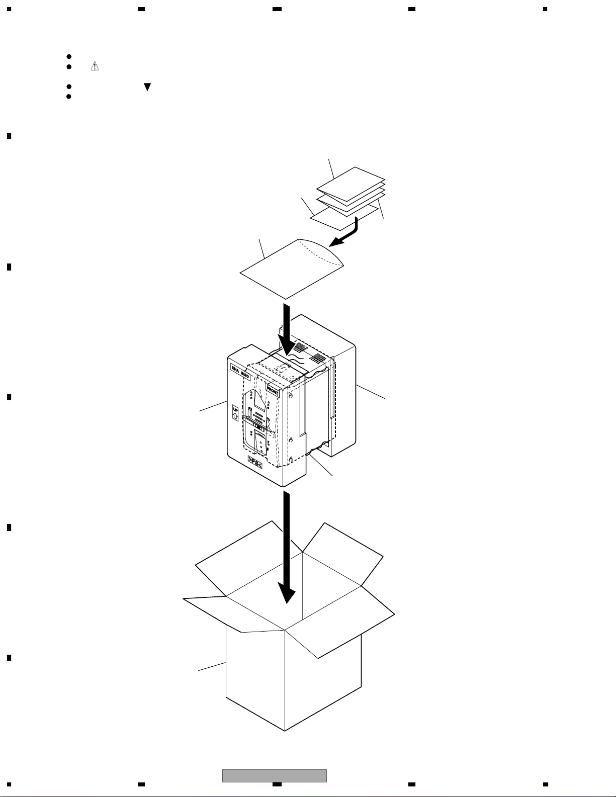
2.1 PACKING
Parts marked by "NSP" are generally unavailable because they are not in our Master Spare Parts List.
The mark found on some component parts indicates the importance of the safety factor of the part.
Therefore, when replacing, be sure to use parts of identical designation.
Screws adjacent to mark on product are used for disassembly.
For the applying amount of lubricants or glue, follow the instructions in this manual.
(In the case of no amount instructions, apply as you think it appropriate.)
NOTES:
1
8
3
4
5
6
7
2

XV-EV51
7
5 678
56
7
8
C
D
F
A
B
E
PACKING parts List
(2) CONTRAST TABLE
XV-EV51/ZLXJ/NC and XV-EV21/ZLXJ/NC are constructed the same except for the following :
Mark No. Description Part No.
1 Operating Instructions XRB3017
(English)
2 Operating Instructions XRC3073
(Chinese)
NSP 3 Polyethylene Bag Z21-038
(0.03 x 230 x 340)
4 Packing Sheet AHG7053
5 Front Pad M XHA3130
6 Rear Pad M XHA3131
7 Packing Case See Contrast table (2)
8 Correct Sheet XRH3007
Mark
No. Description Part No.
Mark No. Symbol and Description XV-EV51/ZLXJ/NC XV-EV21/ZLXJ/NC
7 Packing Case XHD3305 XHD3308
XV-EV51
8
1234
1234
C
D
F
A
B
E
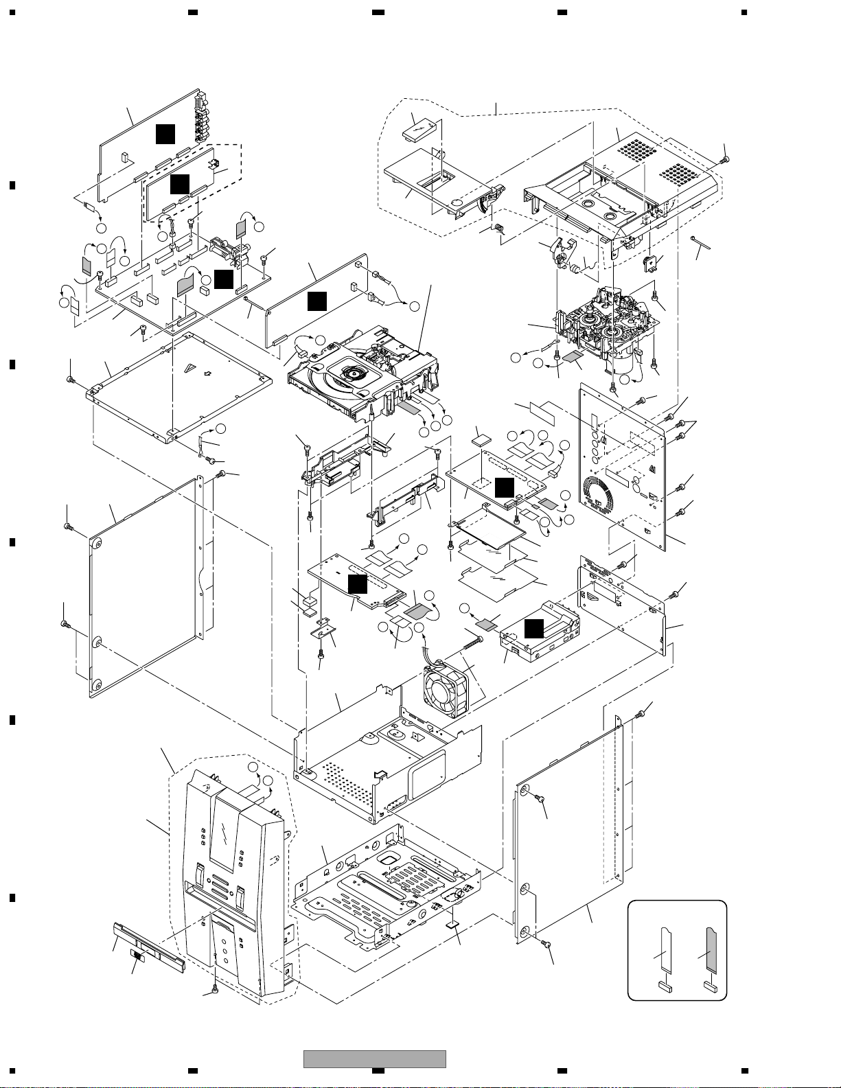
2.2 EXTERIOR SECTION
B
G
A
C
D
F
E
H
O
L
M
M
N
D
E
A
B
F
C
N
G
H
I
L
K
J
K
J
I
O
C
K
B
E
F
A
G
CONTACT SIDE
NON-CONTACT
SIDE
9
32
8
Refer to
"2.4 LOADING MECHA ASSY".
Refer to
"2.3 FRONT PANEL SECTION".
3
2
21
11
32
27
35
24
23
12
5
6
13
14
15
22
20
17
33
34
26
31
10
19
18
1
28
25
29
16
4
30
7
XV-EV51
Only
XV-EV51
Only
40
40
40
40
39
39
44
45
48
46
47
50
39
39
39
40
42
40
43
37
39
39
39
39
39
39
39
39
39
52
38
38
38
38
40
51
49
41
36
43
42
39
40
XV-EV51
9
5 678
56
7
8
C
D
F
A
B
E
EXTERIOR SECTION parts List
(2) CONTRAST TABLE
XV-EV51/ZLXJ/NC and XV-EV21/ZLXJ/NC are constructed the same except for the following :
Mark No. Description Part No.
1 FM/AM TUNER Module AXQ7228
2 IF Assy See Contrast table (2)
3 AF Assy See Contrast table (2)
4 DECK Assy See Contrast table (2)
5 DVDM Assy AWM7684
6 DVD IF Assy AWM7677
7 DSP Assy See Contrast table (2)
8 DECK Mechanism Unit XYM3015
NSP 9 LOADING MECHA Assy VWT1203
10 DC Fan Motor AXM7025
NSP 11 Earth Lead Wire DE012VF0
12 11P Flat Flexible Cable XDD3114
13 13P Flat Flexible Cable XDD3115
14 30P Flat Flexible Cable XDD3116
15 16P Flat Flexible Cable XDD3117
16 Connector Assy 5P XDE3055
NSP 17 Chassis XNA3011
18 Rear Panel A See Contrast table (2)
19 Rear Panel B See Contrast table (2)
20 Mecha Frame XNG3082
21 DVD Shield XNG3083
22 GND Plate XNG3084
23 Ratch Spring ABH7130
24 Damper Assy AXA7052
25 Door Spring L XBH3010
26 Leg Cushion XEB3028
27 Deck Lens XAK3327
28 Deck Door XAN3047
29 Ratch Mold XMR3001
30 Side Bonnet L XNE3026
31 Side Bonnet R XNE3027
32 Binder ZCA-SKB90BK
33 Tray Cap XAK3325
34 DVD Badge XAK3331
35 Top Panel XAK3326
NSP 36 Front Panel Assy See Contrast table (2)
NSP 37 Top Panel Assy XXG3131
38 Screw VPZ30P080FZK
39 Screw BBZ30P080FZK
40 Screw BBZ30P080FMC
41 Screw BPZ30P350FZK
42 Screw VPZ30P080FNI
43 Screw BBZ30P080FNI
44 Adapter 02 L ANW7247
45 Adapter 02 R ANW7248
46 Shield Case ANK7108
47 Heat plate ANG7426
48 Radiation Sheet AEB7255
49 Cushion AEB7267
50 FFC Barrier AEC7443
51 FFC Spacer AEC7442
52 Caution Label VRW1699
Mark
No. Description Part No.
Mark NO Symbol and Description
XV-EV51/ZLXJ/
NC
XV-EV21/ZLXJ/NC
2 IF Assy XWZ3617 XWZ3627
3 AF Assy XWZ3618 XWZ3628
4 DECK Assy XWX3067 XWX3066
7 DSP Assy AWX8059 Not used
18 Rear Panel A XNC3160 XNC3180
19 Rear Panel B XNC3161 XNC3176
NSP 37 Front Panel Assy XXG3129 XXG3130
XV-EV51
10
1234
1234
C
D
F
A
B
E
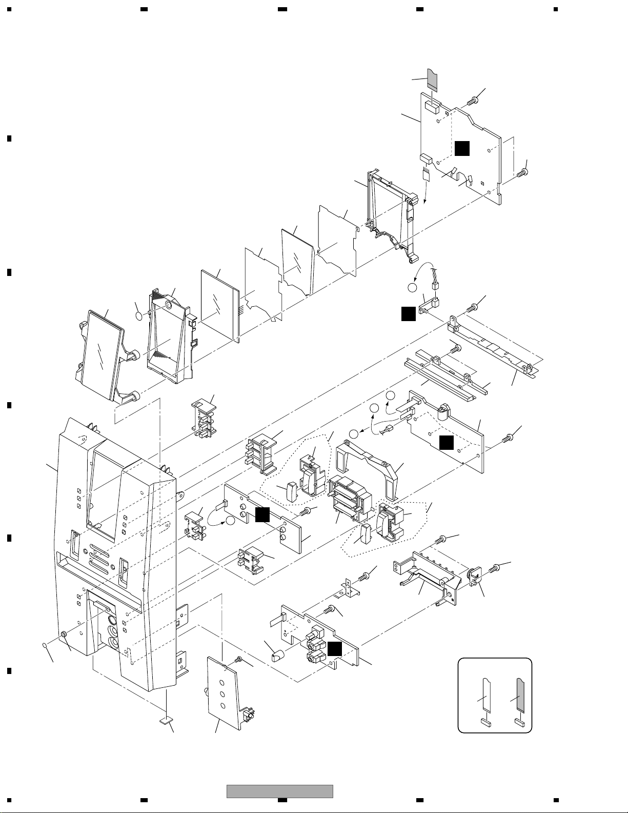
2.3 FRONT PANEL SECTION
A
A
B
B
C
D5108
D5107
CONTACT SIDE
NON-CONTACT
SIDE
J
L
I
H
M
1
6
6
8
9
11
11
13
7
14
21
22
26
35
24
25
29
28
17
16
18
4
19
2
23
27
31
37
32
36
20
10
5
3
30
15
12
34
38
33
33
33
33
33
33
33
33
33
33
39

XV-EV51
11
5 678
56
7
8
C
D
F
A
B
E
FRONT PANEL SECTION parts List
(2) CONTRAST TABLE
XV-EV51/ZLXJ/NC and XV-EV21/ZLXJ/NC are constructed the same except for the following :
Mark No. Description Part No.
1 DISP 1 Assy XWZ3619
2 DISP 2 Assy XWZ3620
3 DISP 3 Assy XWZ3621
4 LED Assy XWZ3622
5 MIC Assy See Contrast table (2)
6 LED (D5107, D5108) NSPWF50BS-9706
7 LCD XAV3016
8 11P Flat Flexible Cable XDD3113
9 LCD Holder XMR3052
10 MIC Knob XAA3024
11 Diffusion Sheet XAK3321
12 Display Window See Contrast table (2)
13 LCD LT Cond XAK3323
14 LCD Cover XAK3324
15 Sensor Cover XAK3330
16 Tray Lens XAK3332
17 FUNC. LT Cond XAK3333
18 LT Cond XAK3334
19 LT Cover XAK3335
20 Jack Door XAN3048
21 Display Button L XAD3149
22 Display Button R XAD3150
23 Play Button XAD3151
24 Dolby Button L XAD3154
25 Dolby Button R XAD3155
26 FUNC. Button L XAD3152
27 FUNC. Cover L XAK3328
28 FUNC. Button R XAD3153
29 FUNC. Cover R XAK3329
30 Front Panel M See Contrast table (2)
31 Damper Assy XXA3029
32 Leg Cushion XEB3028
33 Screw VPZ30P080FZK
34 FUNC. Assy R XAD3158
35 FUNC. Assy L XAD3157
36 Cushion XEB3004
37 Gap Cover XMR3055
38 Magnet XMF3003
39 Screw 2x4 B XBA3011
Mark
No. Description Part No.
Mark No. Symbol and Description XV-EV51/ZLXJ/NC XV-EV21/ZLXJ/NC
5 MIC Assy XWZ3626 XWZ3623
12 Display Window XAK3322 XAK3343
30 Front Panel M XMB3084 XMB3089
XV-EV51
12
1234
1234
C
D
F
A
B
E
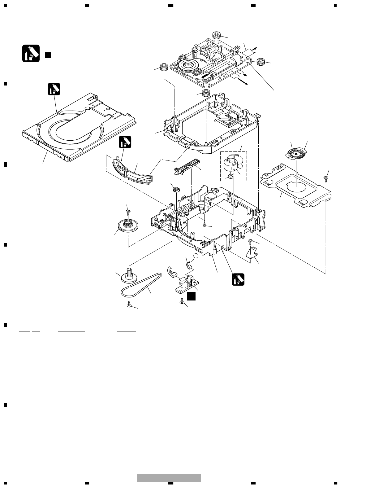
2.4 LOADING MECHANISM ASSY
LOADING MECHANISM ASSY parts List
A
A
To
DVDM
CN8
To DVDM
CN4
To DVDM
CN2
2
3
5
4
12
23
13
17
21
16
22
15
14
22 22
22
2
2
20
18
19
9
1
7
11
10
6
8
8
8
8
D
Refer to
"2.5 TRAVERSE MECHANISM
ASSY-S".
Lubricating Oil
GYA1001
Daifree
GEM1036
Refer to
" Application of Lubricant".
Note :
Lubricating Oil
GYA1001
Mark No. Description Part No.
NSP 1 LOAB Assy VWG2346
2 Traverse Mechanism Assy-S VXX2858
3 Loading Motor Assy VXX2505
4 Motor Pulley PNW1634
5 Carriage DC Motor / 0.3W PXM1027
6 Flexible Cable (26P) VDA1864
7 Connector Assy 2P VKP2253
8 Float Rubber VEB1327
9 Belt VEB1330
10 Stabilizer VNE2253
11 Loading Base VNL1917
12 Float Base DVD VNL1918
13 Drive Cam VNL1919
14 Gear Pulley VNL1921
15 Loading Gear VNL1922
16 Drive Gear VNL1923
17 SW Lever VNL1925
18 Clamper Plate VNE2251
19 Bridge VNE2252
20 Clamper VNL1924
21 Screw JGZ17P028FMC
22 Screw Z39-019
23 Tray VNL1920
Mark No. Description Part No.
XV-EV51
13
5 678
56
7
8
C
D
F
A
B
E
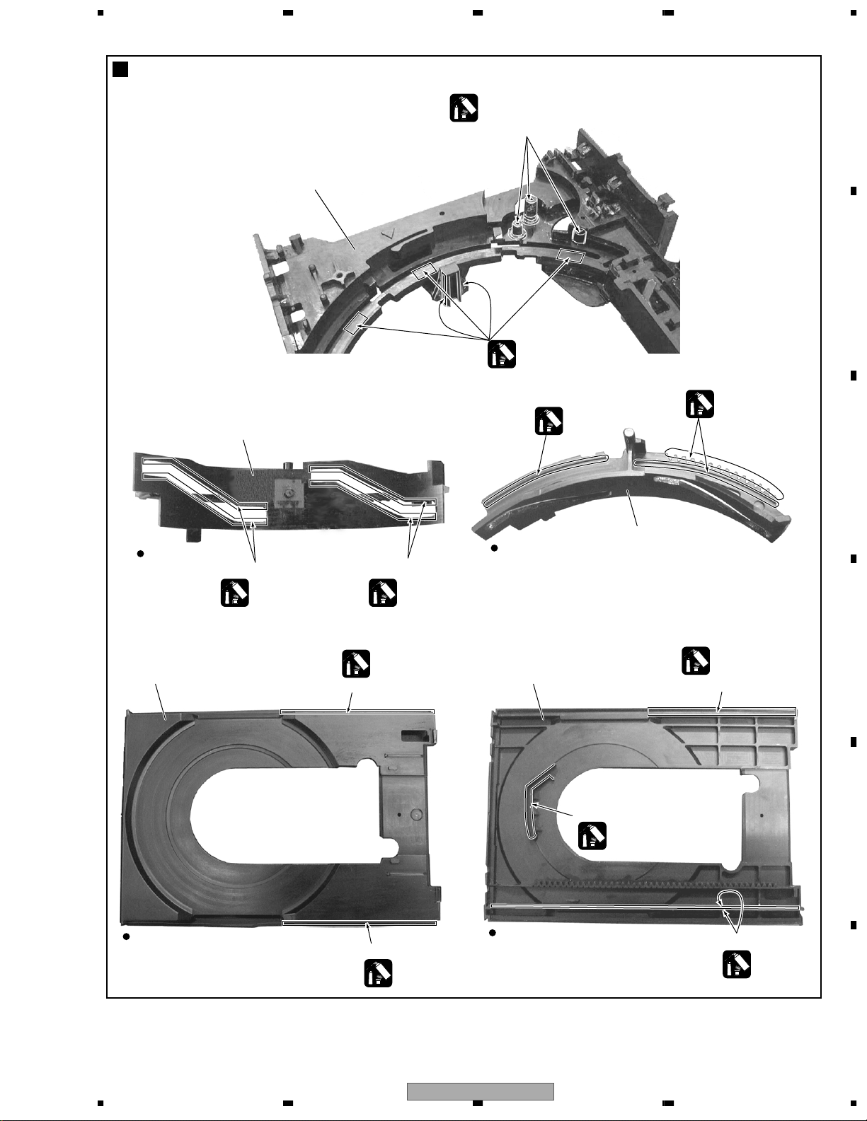
Application of Lubricant
No. 11
Loading Base
Lubricating Oil
GYA1001
Around the shaft
Concave of unevenness
Concave of unevenness
Concave of unevenness
No. 13
Drive Cam
No. 13
Drive Cam
No. 23
Tray
No. 23
Tray
Top View
Rear View
Top View
Bottom View
Daifree
GEM1036
Daifree
GEM1036
Daifree
GEM1036
Daifree
GEM1036
Daifree
GEM1036
Side of the rib
Inner side of a ditch
Inner side of a ditch
Lubricating Oil
GYA1001
Lubricating Oil
GYA1001
Inner side of a ditch
Lubricating Oil
GYA1001
Lubricating Oil
GYA1001
Lubricating Oil
GYA1001

XV-EV51
14
1234
1234
C
D
F
A
B
E
2.5 TRAVERSE MECHANISM ASSY
To
DVDM
CN8
To DVDM
CN4
To SSIB
CN1
12
8
3
7
1
18
16
19
18
10
13
18
10
6
5
5
11
15
14
9
16
2
CONTACT SIDE
NON-CONTACT
SIDE
4 (Adjustment Screw)
Screw Tight
GYL1001
Silicone Adhesive
GEM1037
Silicone Adhesive
GEM1037
17 (Torque : 0.12 ± 0.01 N•m)
17 (Torque : 0.12 ± 0.01 N•m)
Silicone Adhesive
GEM1037
17 (Torque : 0.12 ± 0.01 N•m)

XV-EV51
15
5 678
56
7
8
C
D
F
A
B
E
TRAVERSE MECHANISM ASSY parts List
Mark No. Description Part No.
1 Spindle Motor VXM1088
2 Stepping Motor VXM1090
>
3 Pickup Assy-S OXX8004
4 Skew Screw VBA1080
5 Skew Spring VBH1335
6 Guide Bar VLL1514
7 Sub Guide Bar VLL1515
8 Hold Spring VNC1017
9 Joint Spring VNC1019
10 Support Spring VNC1020
NSP 11 Mechanism Chassis VNE2248
12 Slider VNL1811
13 Spacer VNL1913
14 Joint VNL1914
15 FFC Holder VNL1915
16 Screw BBZ20P050FZK
17 Tapping Screw OBA8009
18 Screw PMA26P100FMC
19 Damper Sheet VEB1335

XV-EV51
16
1234
1234
C
D
F
A
B
E
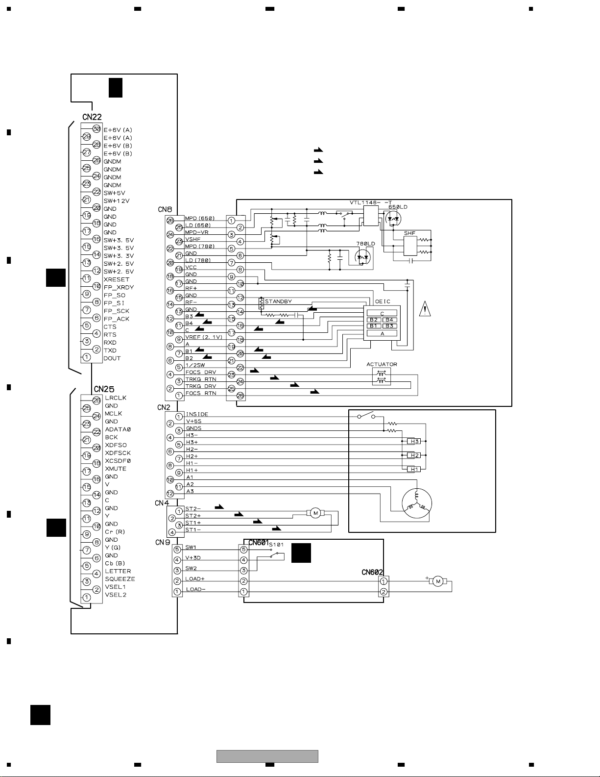
3. BLOCK DIAGRAM AND SCHEMATIC DIAGRAM
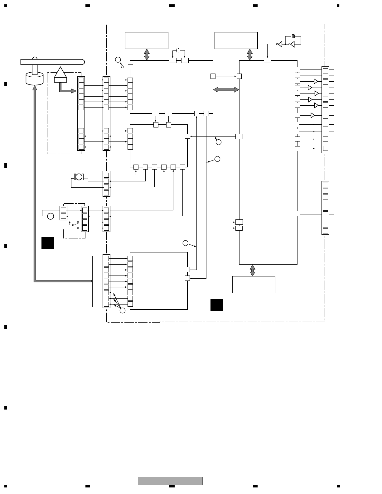
3.1 BLOCK DIAGRAM
CN
CN5903
CN5901
EV-51 : PDC093
EV-21 : PDC097
16,17
5,6
5,6
7
73
348
4
8
RECL
PBL
17 16 2
DSP ASSY
XV-EV51 Only
H
DECK ASSY
E
IF ASSY
B
DVDM ASSY
DVD IF ASSY
F
G
DISP1 ASSY
J
(D)
(D)
(V)
(Y)
(C)
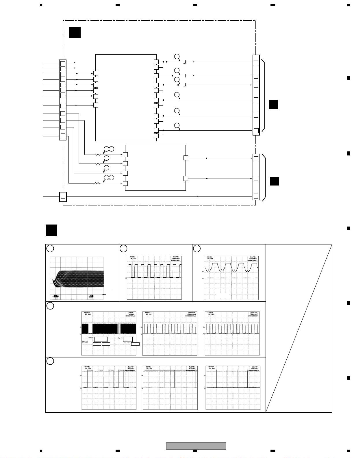
3.1.1 SIGNAL ROUTE(1/2)
(REC)
Refer to 3.1.2 SIGNAL ROUTE(2/2)
CN5509
CN5801
CN2506
CN5101
XV-EV51
17
5 678
56
7
8
C
D
F
A
B
E
M-EV51
(POWER AMPLIER)
Service Manual
Order No.RRV2663
CN8701
JA5401
CN3002
CN8901
CN5503
CN5501
MIC ASSY
AF ASSY
C
M
FM/AM TUNER
MODULE
A
SIGNAL ROUTE
: PB SIGNAL
: RECORDING SIGNAL
(D)
(PB)
(PB)
(PB)
(PB)
(PB)
(TX)
(REC)
(REC)
: AUDIO SIGNAL (TUNER)
(V)
(V)
(TX)
(TX)
: V SIGNAL VIDEO
(Y)
(Y)
: Y SIGNAL VIDEO
(C)
(C)
: C SIGNAL VIDEO
(SL)
(FL)
: SL AUDIO SIGNAL
: FL AUDIO SIGNAL
: C AUDIO SIGNAL
(SW)
(C)
: SW AUDIO SIGNAL
: DIGITAL AUDIO ROUTE
J5401
CN8101
CN5504
CN8301
XV-EV51
18
1234
1234
C
D
F
A
B
E
CN4
(4P)
IC301
L6315ATXXTY
FRONT END IC
Spindle
Motor
B1
X301
20MHz
B2
FACT
B3
B4
A
A
RFSACD
FREOUT FREIN
OUT_DATA(0) S_DATA
FE_DATA
RF(TP)
B
C
D
E
F
VM4-
VM4+
VM3+
VM3-
C
Stepping
Motor
(Carriage)
FDO
T_DRV
T_RTN
F_RTN
F_DRV
ST1-
ST1+
ST2+
ST2-
PICKUP
ASSY
CN151
(26P)
(26P)
D
LOAB ASSY
F
DVDM ASSY
M
IC351
M56788AFP
FTS Driver
IC251
BA6664FM
Spindle
Driver
20
21
15
16
19
17
7
6
12
11
8
10
10
3
84
B_OUT
25
16
HSYNC
_PWM0
131
123
TDO
FG
LOAD_DRV
SPDL
PDM
FG
SPDL PDM
TACT
IN4-
VM1+
IN5-
IN3-
PC(2) PC(6)
124
116
132
PIXCLK
120
12
18
16
25
24
13
12
H1+
FG
EC
H1+
9
24
22
10
9
4238
3 20
34
VM1-
35
VM2-
31
VM2+
32
VM5-
15
VM5+
14
17
24
25
26
23
3
2
1
4
4
3
CN2
(12P)
CN22
(30P)
CN25
(26P)
CN401
(13P)
4
2
1
IC302
K6T1008V2E-TB70
1M SRAM
Work RAM for Error Correction
IC604
K4S641632F-TC75
64M SDRAM
Work RAM for MPEG Decode
IC603
VYW1948
8M FLASH ROM
• RF Demodulation
• Servo Control
• Servo Decode
• Error Correction
IC601
STI5519AVB-B0C
BACK END IC
• System Control
• MPEG Video Decode
• Video Encode
• Video DAC
• Audio Decode
(MP3, Dolby)
• Sub-picture Decode
• Spindle Drive
• FG Detection
Focus, Tracking,
Stepper and
Loading Drive
X601
27MHz
Loading
Motor
Assy
+–
M
H1-H1-
10
5
H2+H2+
11
6
H2-H2-
12
7
H3+H3+
13
8
H3-H3-
14
9
A1A1
7
3
A2A2
4
2
A3A3
2
1
1
3562
IC605 TC7WU04FU
Q607
G_OUT
26
Q606
R_OUT
27
DAC_SCLK
51
PCMDATA0
52
PCKCLK
55
Q605
Y_OUT
32
Q604
C_OUT
33
Q603
CV_OUT
34
SPDIF
DOUT
A_BCK
57
Q602
A_DATA0
A_MCLK
LRCLK
56
A_LRCK
PIO381
7
PIO382
8
SQUEEZ
LETTER
LOD+
SW2
SW1
LOD-
3.3V
CN602
(2P)
CN601
(5P)
CN9
(5P)
1
2
1
2
1
2
33
55
XCLOSE
OPEN
S101
205
204
XCLOSE
OPEN
3
4
24
5
26
21
7
9
11
13
22
15
5
3
4
2
1
3.1.2 SIGNAL ROUT(2/2)
XV-EV51
19
5 678
56
7
8
C
D
F
A
B
E
G
DVD IF ASSY
Cb IN
YOUT b
YOUT a
COUT
VOUT b
VOUT a
CYOUT b
CYOUT a
CrOUT b
CrOUT a
CbOUT b
CbOUT a
Y
14
28
27
V
31
30
G
25
24
R
19
18
B
22
21
C
33
CN1961
(30P)
CN1901
(30P)
CN1962
(26P)
CN1902
(16P)
IC801
MM1567AJ
6 IN • 6 OUT
VIDEO AMP
BCKIN
1
DATA
2
MCLK
16
LRCKIN
3
IC711
PCM1742KE
Audio 2ch DAC
• LPF
• AMP
• Driver
1
B
CY IN
12
G
Cr IN
16
R
Y IN
6
S_Y
C IN
2
S_C
R721
R722
R723
V IN
4
V
DIGITAL
OUT
Vout L
LOUT
7
Vout R 8
ROUT
C812
C822
C832
AUDIO
OUT
3
4
24
5
26
21
7
9
11
13
22
15
10
24
14
16
6
8
30
28
12
7
12
11
8
9
10
2 5
6
1
3 4
1– =: Refer to "3.1.3 WAVEFORMS".
3.1.3 WAVEFORMS
CN5903
B
B
CN5901
1
IC301 - pin 3 [RF]
V: 200mV/div. H: 0.1µsec/div.
2
IC251 - pin 24 [FG]
V: 1V/div. H: 5msec/div.
GND
5
IC601 - pin 116 [LOAD_DRV]
V: 1V/div. H: 5µsec/div.
4
IC301 - pin 42 [SPDL_PDM]
DVDM ASSY
F
[Tray stops][Tray is opening][Tray is closing]
[PLAY][STOP→PLAY→STOP] [STOP]
STOP STOPPLAY
Accelertar
ON
Brakes
ON
V: 2V/div. H: 500nsec/div.
V: 2V/div. H: 500nsec/div.
3
IC251 - pin 2, 4, 7
[Spidle driver -A3, A2, A1]
V: 2V/div. H: 2msec/div.
[PLAY]
V: 2V/div. H: 1sec/div.
Note : The encircled numbers denote measuring point in the schematic diagram.
Measurement condition
: No. 1 and 2 : reference A1 (DVD), T2-chp 19, Color-bar
XV-EV51
20
1234
1234
C
D
F
A
B
E
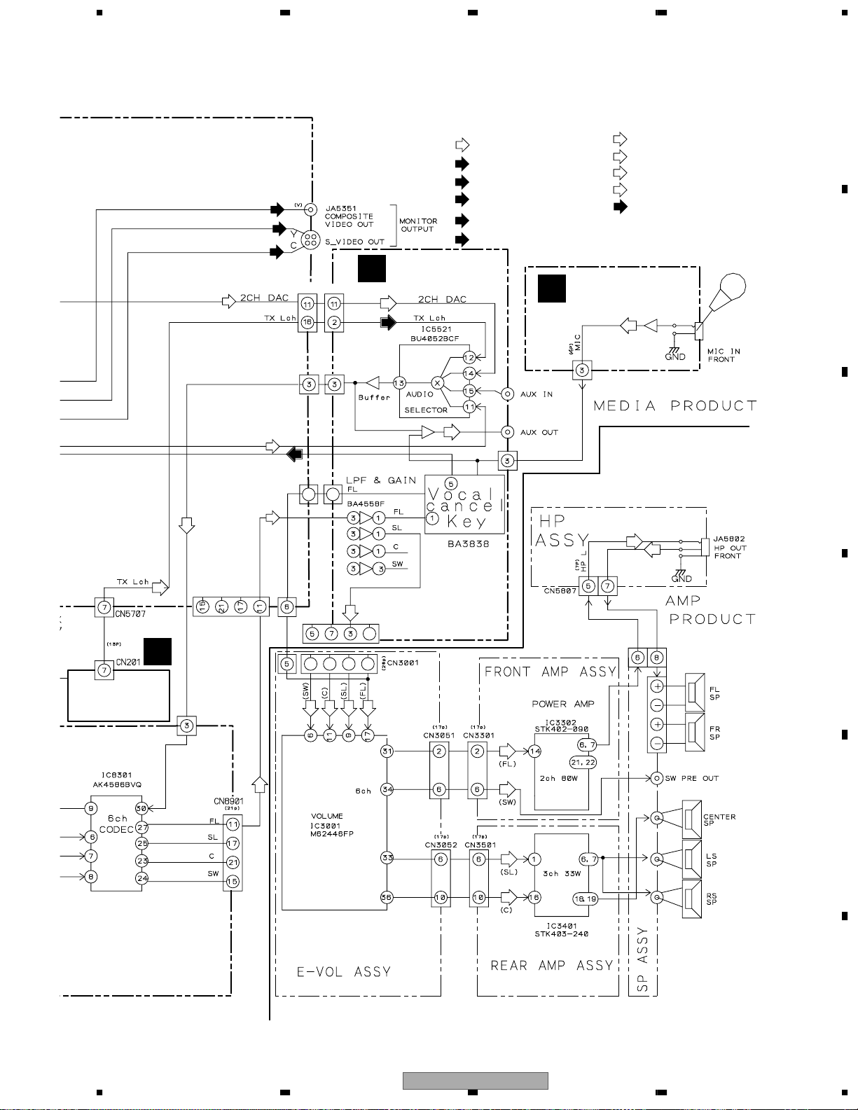
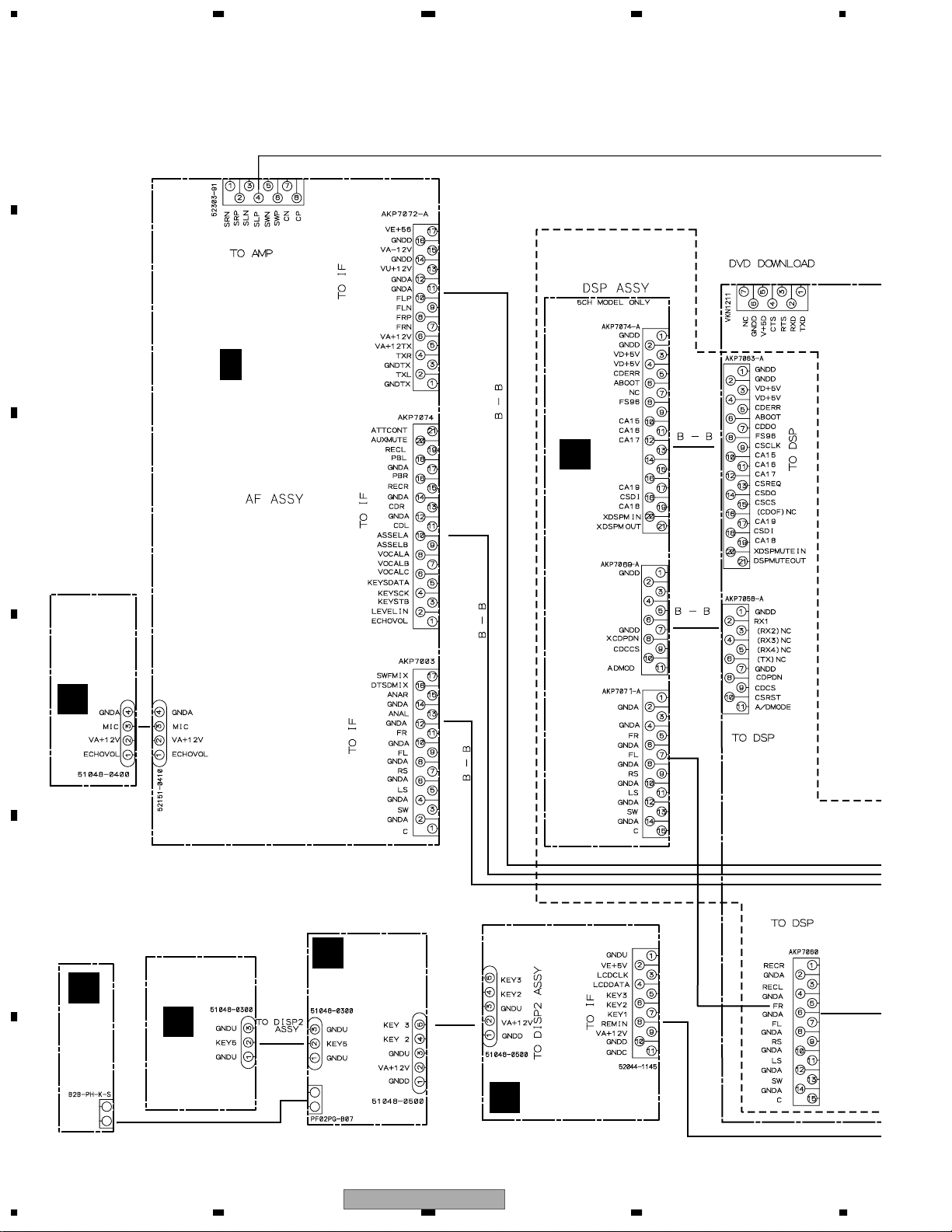
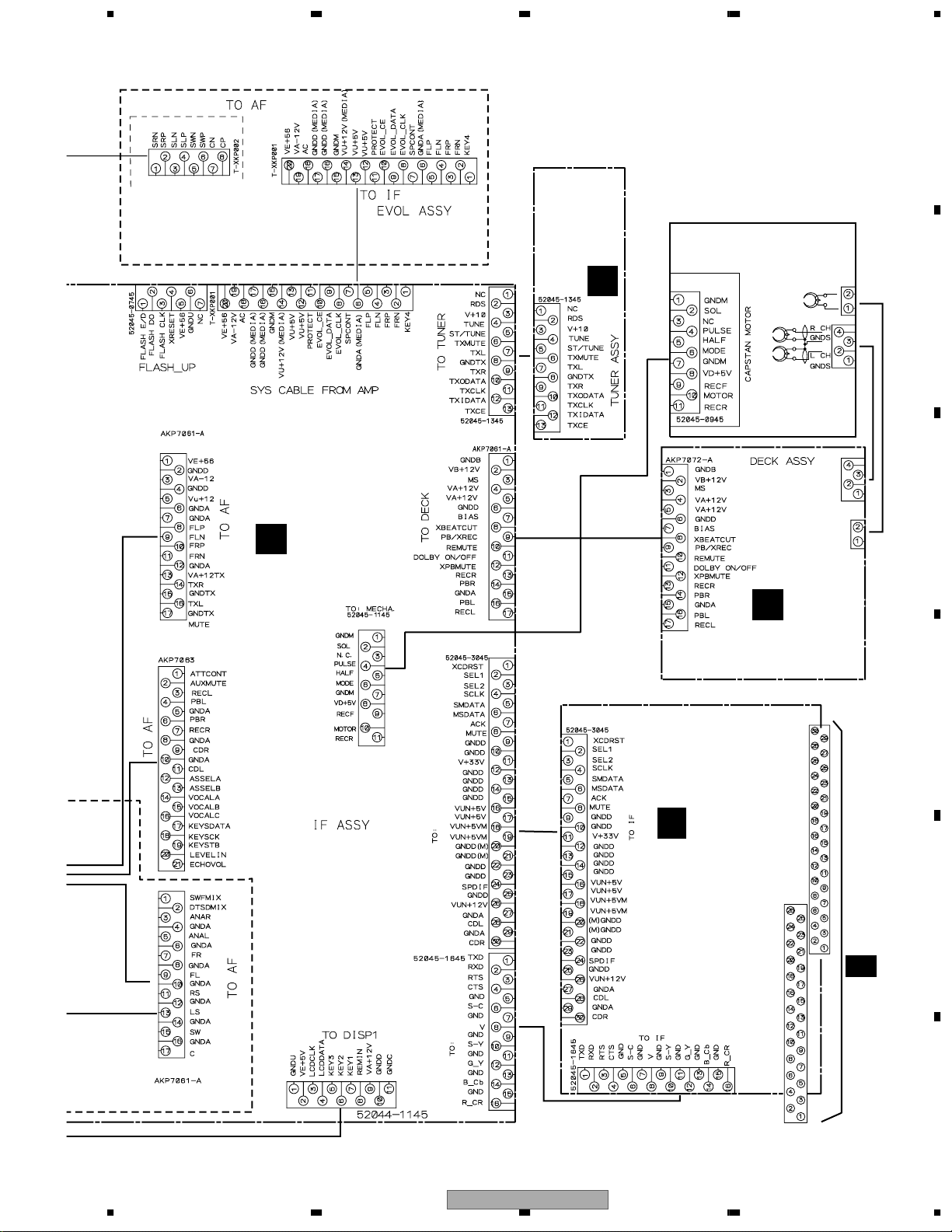
3.2 OVERALL WIRING DIAGAM
XV-EV51
Only
DSPCK
DSPRQ
DSPRO
XDSPRST
DIRRX1
DIRRX2
DIRRX3
DIRRX4
DIRTX
ADCR
ADCL
DSPCS
CDCOVF
AF ASSY
(XWZ3618 / XV-EV51)
(XWZ3628 / XV-EV21)
C
1/2
- 2/2
MIC ASSY
(XWZ3626/
XV-EV51)
(XWZ3623/
XV-EV21)
M
J
L
DSP ASSY
(AWZ8059 / XV-EV51)
LED ASSY
(XWZ3622)
K
DISP3 ASSY
(XWZ3621)
DISP2 ASSY
(XWZ3620)
DISP1 ASSY
(XWZ3619)
H
I
3.2.1 OVERALL WIRING DIAGRAM(MEDIA PART 1/2)
CN5508
CN5902
CN8751
CN8101
CN8701
CN8901
CN8301J5401
CN5507
CN5506
CN8002
CN8001
CN8003
CN5203
5301
J5202
J5203
J5102
CN5102
CN5101
Note : When ordering service parts, be sure to refer to "EXPLODED VIEWS and PARTS LIST" or "PCB PARTS LIST"
XV-EV51 Only
XV-EV51
21
5 678
56
7
8
C
D
F
A
B
E
DVD IF ASSY
DVD IF ASSY
IF ASSY
(XWZ3617 / XV-EV51)
(XWZ3627 / XV-EV21)
B
A
FM/AM TUNER
MODULE
(AXQ7228)
DECK ASSY
(XWX3067 / XV-EV51)
(XWX3066 / XV-EV21)
DECK
MECHA. (XYM3015)
E
DVD IF ASSY
(AWM7677)
DVDM ASSY
(AWM7684)
G
1/2
F
- 2/2
M-EV51
(STEREO POWER AMPLIFIER)
Service Manual
order no. RRV2663
CN5505
CN5903
CN5802
CN5801
CN2506
CN2301
CN2302
CN5503
CN5501
CN5502
CN5504
CN5509
CN5901
CN1902
CN1962
CN1961
CN1901
XDD3113
XDD3117
XDD3115
REC/PB
HEAD
ERASE
HEAD
XDD3116
CN5701
CN201
CN3001
CN3002
XV-EV51 Only
XV-EV51
22
1234
1234
C
D
F
A
B
E
ABCDE
D
LOAB ASSY
(VWG2346)
D
LOADING
MOTOR ASSY
: VXX2505
SPINDLE
MOTOR
: VXX1088
PICKUP ASSY-S
(OXX8003)
STEPPING MOTOR
: VXM1090
: FOCUS SERVO LOOP LINE
: TRACKING SERVO LOOP LINE
(F)
(T)
: SLIDER SERVO LOOP LINE
(S)
(F)
(F)
(F)
(T)
(F)
(F)
(F)
(F)
(F)
(T)
(F)
(T)
(T)
(F)
(S)
(S)
(S)
(S)
DVDM ASSY
(AWM7684)
1/2
F
- 2/2
DVD IF ASSY
(AWM7677)/CN1962
G
DVD IF ASSY
(AWM7677)/CN1961
G
3.2.2 OVERALL WIRING DIAGRAM (MEDIA PART 2/2)

XV-EV51
23
5 678
56
7
8
C
D
F
A
B
E
CDAB
1
IC301 - pin 3 [RF]
V: 200mV/div. H: 0.1µsec/div.
3
IC711 - pin 3 [AUDIO DAC -LRCK]
V: 2V/div. H: 5µsec/div.
2
IC251 - pin 24 [FG]
V: 1V/div. H: 5msec/div.
1 2
IC711 - pin 16 [AUDIO DAC -MCK]
V: 1V/div. H: 20nsec/div.
IC711 - pin 1 [AUDIO DAC -BCK]
V: 2V/div. H: 200nsec/div.
GND
5
IC601 - pin 116 [LOAD_DRV]
V: 1V/div. H: 5µsec/div.
4
IC301 - pin 42 [SPDL_PDM]
5
4
IC711 - pin 3
[AUDIO DAC -LRCK]
V: 2V/div. H: 500nsec/div.
IC711 - pin 1
[AUDIO DAC -BCK]
V: 2V/div. H: 500nsec/div.
6
IC711 - pin 2
[AUDIO DAC -DATA]
V: 2V/div. H: 500nsec/div.
8
Foot of C842 (IC801 - pin 24, 25)
[Component Video output -Y]
V: 1V/div. H: 10µsec/div.
9
Foot of C852 (IC801 - pin 18, 19)
[Component Video output -Cb]
V: 2V/div. H: 10µsec/div.
11
Foot of C832 (IC801 - pin 27, 28)
[S Video output -Y]
V: 1V/div. H: 10µsec/div.
12
Foot of C822 (IC801 - pin 33)
[S Video output -C]
V: 1V/div. H: 10µsec/div.
10
Foot of C862 (IC801 - pin 21, 22)
[Component Video output -Cr]
V: 2V/div. H: 10µsec/div.
7
Foot of C812 (IC801 - pin 30, 31)
[Composite Video output]
V: 1V/div. H: 10µsec/div.
DVDM ASSY
F
DVD IF ASSY
G
GND
4
5
6
8
9
11
12
10
[Tray stops][Tray is opening][Tray is closing]
[PLAY][STOP→PLAY→STOP] [STOP]
STOP STOPPLAY
Accelertar
ON
Brakes
ON
V: 2V/div. H: 500nsec/div. V: 2V/div. H: 500nsec/div.
3
IC251 - pin 2, 4, 7
[Spidle driver -A3, A2, A1]
V: 2V/div. H: 2msec/div.
[PLAY]
V: 2V/div. H: 1sec/div.
Note : The encircled numbers denote measuring point in the schematic diagram.
Measurement condition
: No. 1 and 2 : reference A1 (DVD), T2-chp 19, Color-bar
Measurement condition
: No. 1 to 6 : reference A1 (DVD), T2-chp 1
No. 7 to 12 : reference A1 (DVD), T2-chp 19, Color-bar
3.1.3 WAVEFORMS
XV-EV51
24
1234
1234
C
D
F
A
B
E
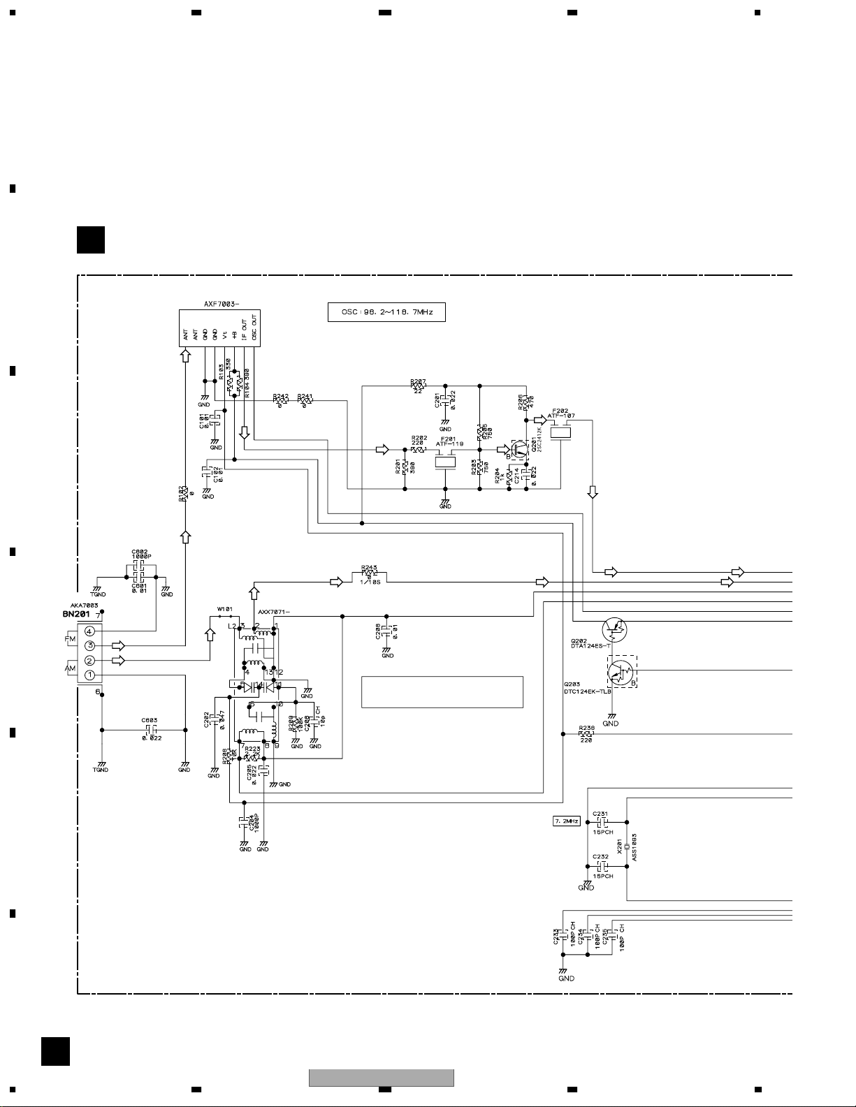
3.3 FM/AM TUNER MODULE
A
FM FRONT END
MW RF TUNING BLOCK
A
OSC : 981 - 2052kHz 9k step
FM/AM TUNER MODULE (AXQ7228)
(AM)
(AM)
(AM)
(AM) (AM)
(AM)
(FM)
(FM) (FM)
(FM)
(FM)
(FM)
(FM) (FM)
(FM)
(FM)
XV-EV51
25
5 678
56
7
8
C
D
F
A
B
E
A
L201
ATE7003
CN5701
B
CN201
: AUDIO SIGNAL ROUTE (TUNER)
(TX)
: AM SIGNAL ROUTE
(AM)
: FM SIGNAL ROUTE
(FM)
(AM)
(AM)
(FM)
(AM)
(AM)
(AM)
(AM)
(AM)
(AM)
(FM)
(AM)
(FM)
(TX)
(TX)
(TX)
(TX)
(TX)
(FM)
: The power supply is shown with the marked box.
XV-EV51
26
1234
1234
C
D
F
A
B
E
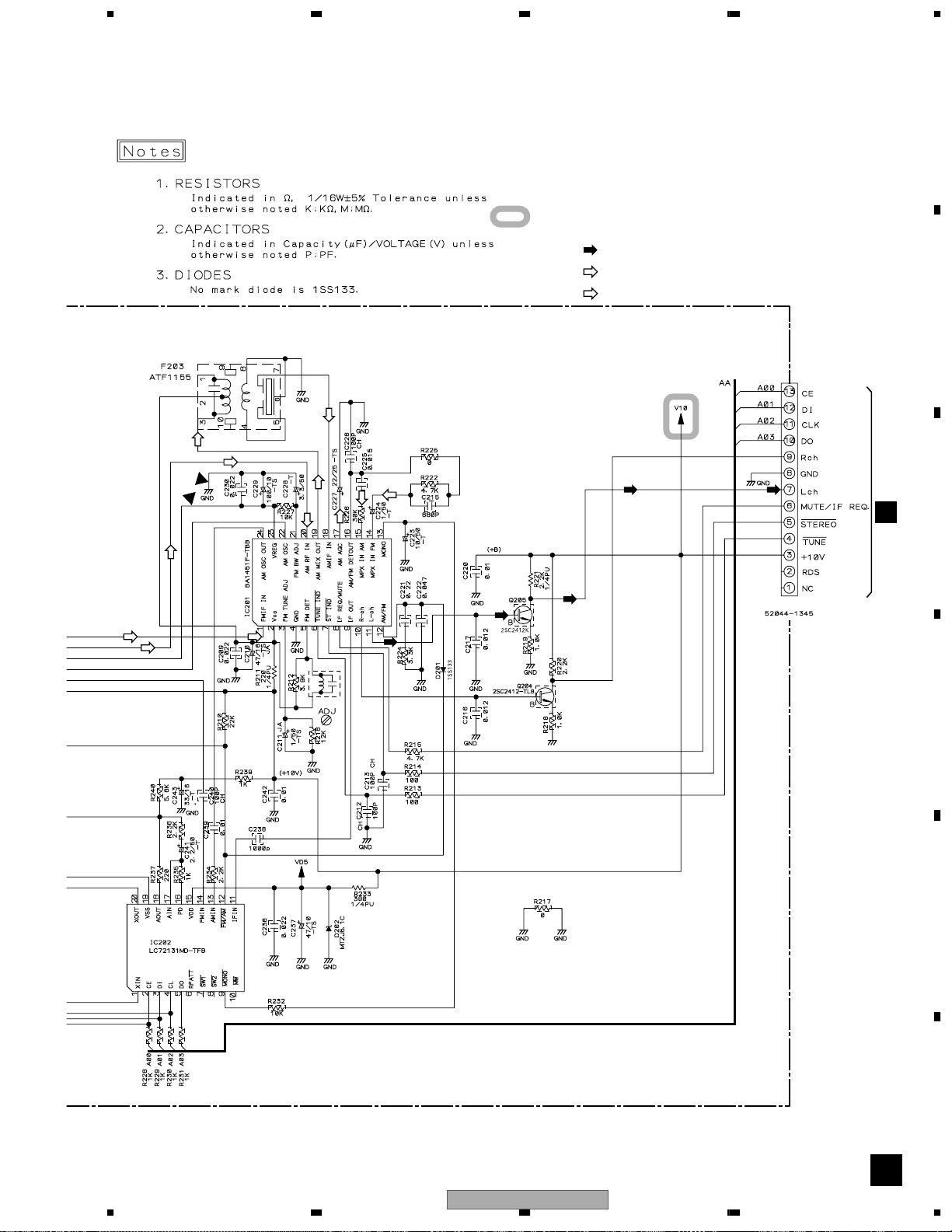
3.4 IF ASSY
B
EV-
51
EV-51
Only
EV-
21
XV-EV51
ONLY
EV-51
EV-21
IF ASSY
(XWZ3617
/ XV-EV51)
(XWZ3627
/ XV-EV21)
B
G
CN1902
CN5508
CN5506
CN5505
CN5903
CN5504
CN5503
K
CN8002
K
CN8001
K
CN8003
CN8751
CN8101
C
CN8901
2/2
C
2/2
C
2/2
G
CN1902
CN5507
CN5502
CN5902
CN5901
(TX)
(CD)
(D)
(CD)
(CD)
(D)
XV-EV21
Only
(S_Y)
(S_C)
(S_Y)
(S_Y)
(S_C)
(V)
(V)
XV-EV51
27
5 678
56
7
8
C
D
F
A
B
E
B
EV-51
EV-21
EV-51
EV-51
: The power supply is shown with the marked box.
J
CN5101
A
CN201
E
CN2506
To. Mecha Deck
SIGNAL ROUTE
: CD AUDIO SIGNAL ROUTE
: AUDIO SIGNAL ROUTE (TUNER)
: DIGITAL SIGNAL ROUTE
(TX)
(CD)
CN5802
CN5701
CN5501
CN5509
TO M-EV51 or M-EV21 Power Amplfier
CN5801
(TX)
(D)
XV-EV21
Only
(S_C)
(S_Y)
: S-VIDEO OUT C SIGNAL ROUTE
(V)
: V SIGNAL ROUTE
: S-VIDEO OUT Y SIGNAL ROUTE
XV-EV51
28
1234
1234
C
D
F
A
B
E
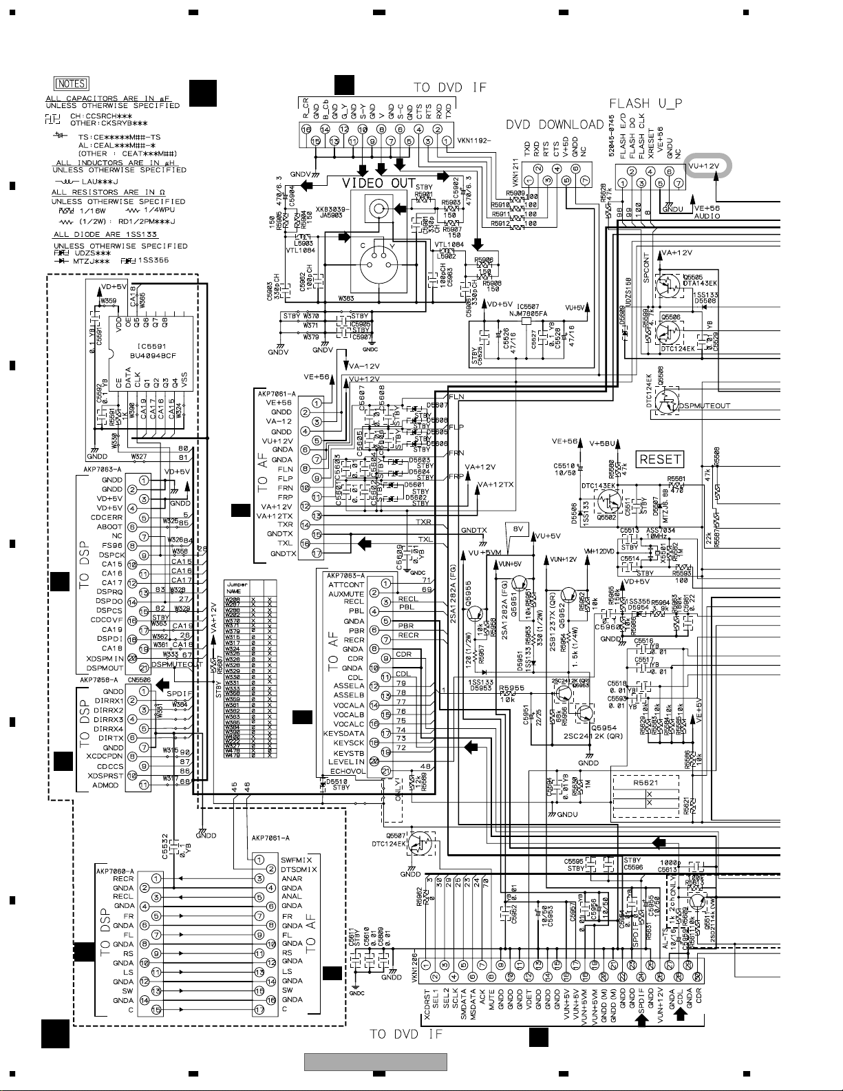
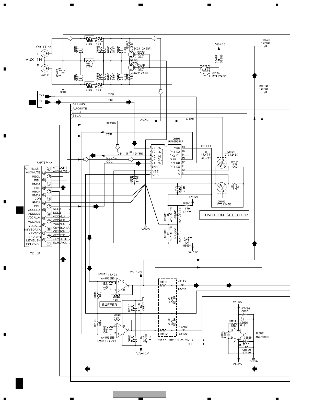
3.5 AF ASSY(1/2)
C
1/2
EV-51
EV-21
C
2/2
B
CN5504
CN8101
(REC) (REC)
(REC) (TX)
(TX) (REC)
(TX)
(TX) (TX)
(PB)
(PB)
(REC)
(REC)
(REC)
(CD)
(CD)
(AUX)
(AUX)
(AUX)
(AUX)
(CD)(CD)
XV-EV51 Only
XV-EV51
29
5 678
56
7
8
C
D
F
A
B
E
C
1/2
: The power supply is shown with the marked box.
AF ASSY
(XWZ3618 / XV-EV51)
(XWZ3628 / XV-EV21)
C
SIGNAL ROUTE
: PB SIGNAL
: RECORDING SIGNAL
(PB)
CN8301
JA8401
1/2
M
J5401
C
2/2
C
2/2
C
2/2
(REC)
(REC)
(REC)
(REC)
(REC)
(REC) (REC)(TX)
(TX)
(CD)
(CD)
(CD)
: AUDIO SIGNAL (TUNER)
(CD)
(TX)
: CD SIGNAL
(AUX)
: AUX SIGNAL
(MIC)
(MIC)
(MIC) (MIC)
(MIC)
: MIC OUT SIGNAL
EV21 Only
XV-EV51 Only
XV-EV51
30
1234
1234
C
D
F
A
B
E
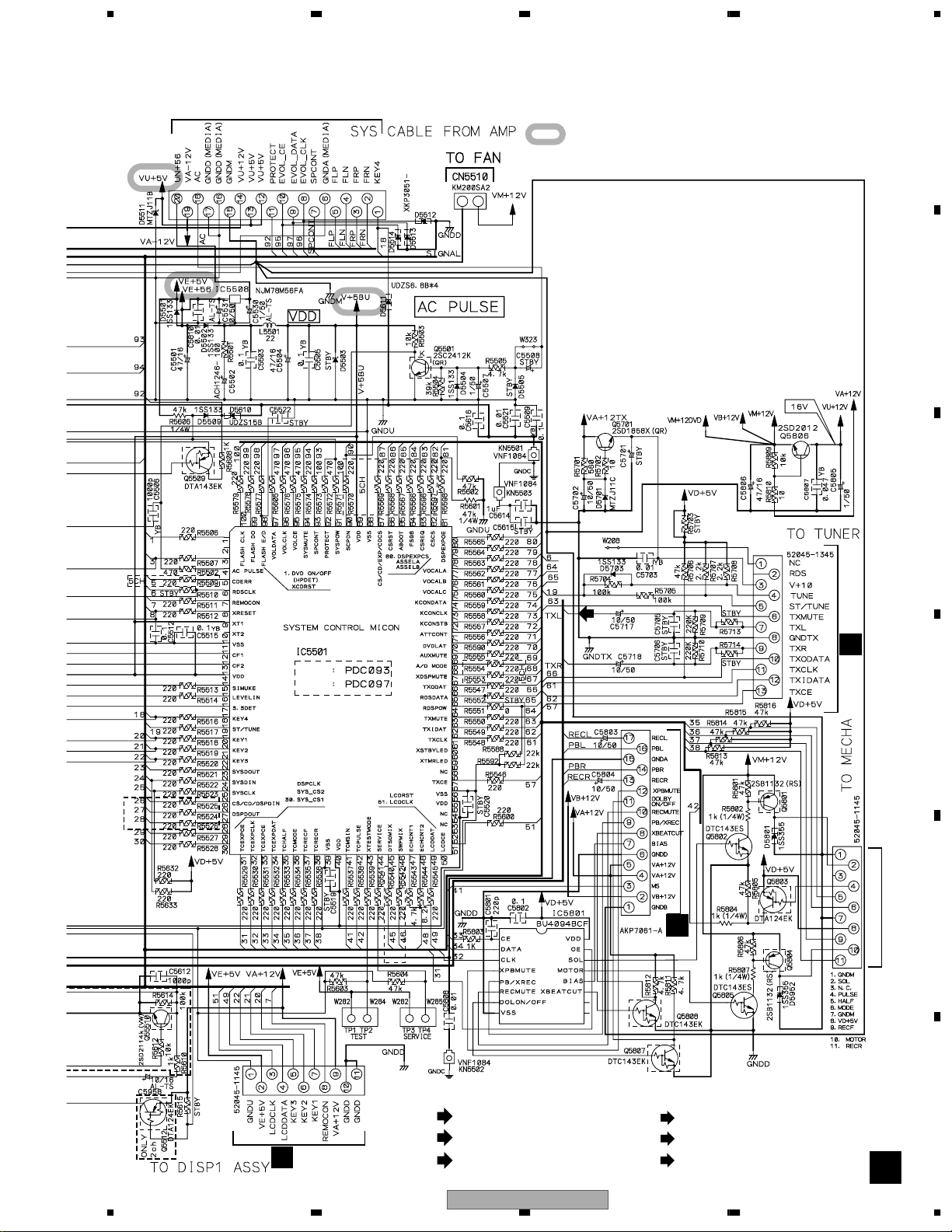
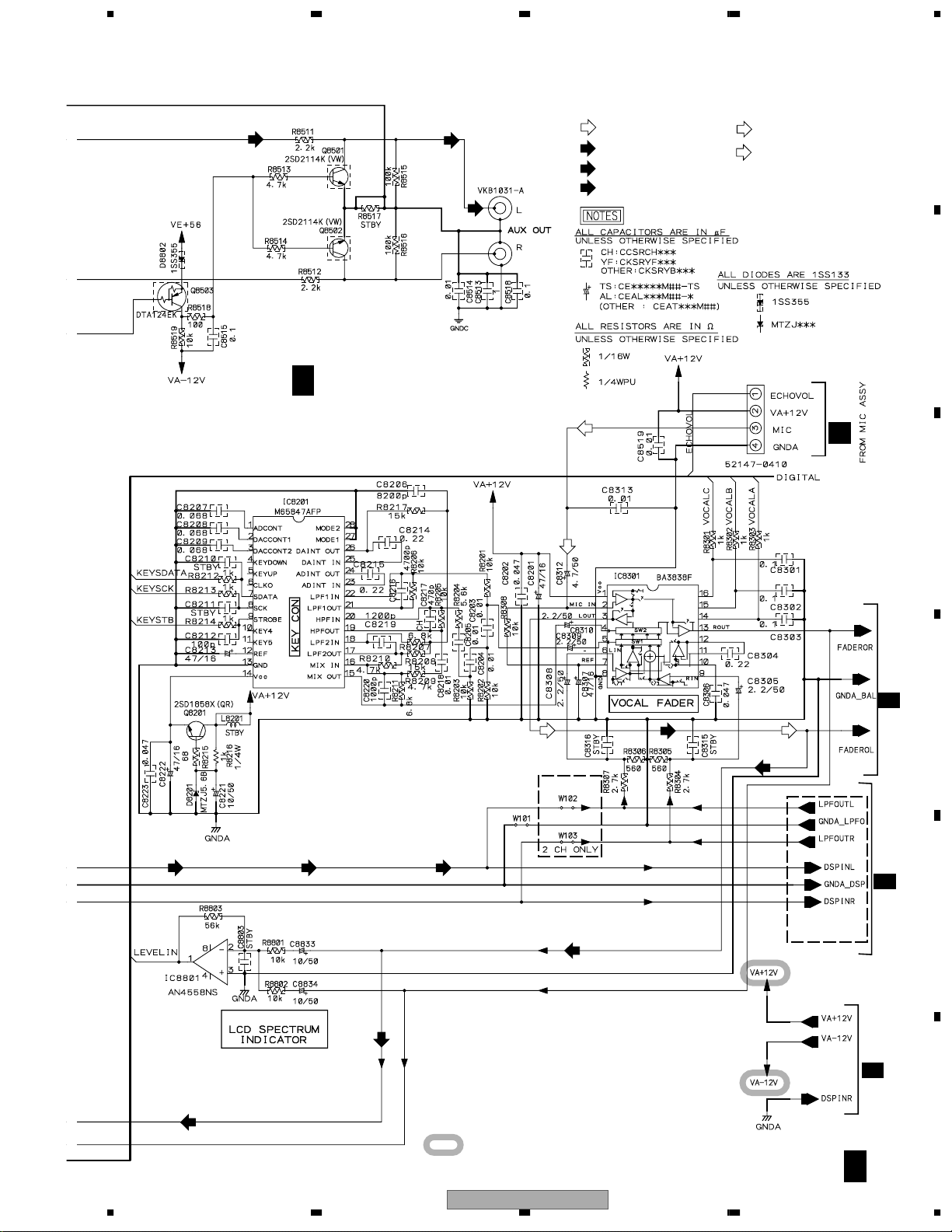
3.6 AF ASSY(2/2)
C
2/2
C
B
1/2
C
1/2
CN5505
CN8751
XV-EV51
Only
SIGNAL ROUTE
: MIC SIGNAL
(MIC)
(MIC) (MIC)
: AUDIO SIGNAL (TUNER)
(TX)
Loading...