


Philips FW-C30-21 User Manual

Toll Free Help Line
Ligne d'assistance en service libre
Linea de ayuda telefónica sin cargo
800-531-0039
FW-
C30
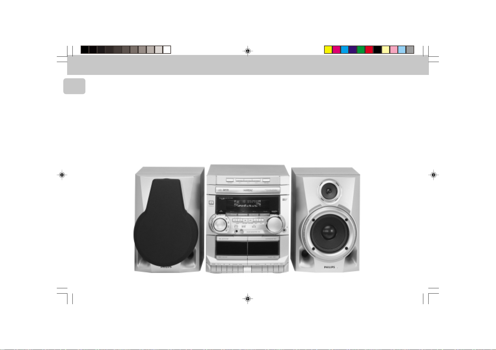
Mini Hi-Fi Systems
avec Changeur de 3 CD
pg 01-24/C30/21&/30-En 3/3/00, 4:23 PM1
3139 116 19371
English
México
Français
Español
Es necesario que lea cuidadosamente su instructivo de manejo.
PRECAUCIÓN - ADVERTENCIA
No abrir, riesgo de choque eléctrico
Verifique que el voltaje de alimentación
Para evitar el riesgo de choque eléctrico, no quite la tapa.
En caso de requerir servicio, dirijase al personal calificado.
ATENCIÓN
sea el requerido para su aparato
Descripción: Minisistema de Audio
Modelo: FW-C30/21
Alimentación: 110–127/220–240 V; ~50–60 Hz
Consumo: 70 W
Importador: Philips Mexicana, S.A. de C.V.
Domicilio: Norte 45, #669, Col. Industrial Vallejo
Localidad y Telefono: C.P. 02300 México D.F., Tel. 728 42 00
Exportador: Philips Hong Kong
País de Origen: China
Nº de Serie:
LEA CUIDADOSAMENTE ESTE INSTRUCTIVO
ANTES DE USAR SU APARATO.
2
pg 01-24/C30/21&/30-En 3/3/00, 4:23 PM2
3139 116 19351
3139 116 18461
English .....................................4
English
CLASS 1
LASER PRODUCT
Français .................................25
Español ..................................47
.................................................69
Warranty ................................89
Australia/New Zealand/Mexico
Français
Español
pg 01-24/C30/21&/30-En 3/3/00, 4:23 PM3
3
3139 116 19351
English
4
pg 01-24/C30/21&/30-En 3/3/00, 4:23 PM4
3139 116 19351

CONTENTS GENERAL INFORMATION SAFETY INFORMATION
General Information .................5
Safety Information ....................5
Preparation .......................... 6 - 7
Controls................................. 8 - 9
Operating The System .... 10 - 11
CD....................................... 12 - 14
Aux............................................. 14
Tuner .................................. 15 - 16
Tape ................................... 17 - 18
Karaoke..................................... 18
Recording ......................... 19 - 20
Clock .........................................20
Timer..........................................21
Sleep Timer ............................. 21
Specifications .........................22
Maintenance............................ 23
Troubleshooting .............. 23 - 24
IMPORTANT:
PLEASE NOTE THAT THE
VOLTAGE SELECTOR
LOCATED AT THE REAR OF
THIS SYSTEM IS PRESET AT
220V FROM THE FACTORY.
FOR COUNTRIES THAT
OPERATE AT 110V, PLEASE
ADJUST TO 110V BEFORE YOU
SWITCH ON THE SYSTEM.
General Information
• The type plate (which contains the
serial number) is located at the rear
of the system.
• Recording is permissible if
copyright or other rights of third
parties are not infringed.
Environmental Information
All unnecessary packaging has been
omitted. We have tried to make the
packaging easy to separate into three
materials: cardboard (box), polystyrene
foam (buffer) and polyethylene (bags,
protective foam sheet).
Your system consists of materials which
can be recycled and reused if disassembled
by a specialized company. Please observe
the local regulations regarding the disposal
of packaging materials, exhausted
batteries and old equipment.
Accessories
– Remote control
– Batteries (two AA size) for remote
control
– AM loop antenna
– FM wire antenna
– AC power cord
(Supplied)
Safety Information
• Before operating the system, check that
the operating voltage indicated on the
typeplate (or the voltage indication
beside the voltage selector) of your
system is identical with the voltage of
your local power supply. If not, please
consult your dealer. The typeplate is
located at the rear of your system.
• When the system is switched on, do not
move it around.
• Place the system on a solid base (e.g. a
cabinet).
• Place the system in a location with
adequate ventilation to prevent internal
heat build-up in your system.
Allow at least 10cm clearance from the
rear and the top of the unit and 5cm
from each side.
• Do not expose the system to excessive
moisture, rain, sand or heat sources.
• Under no circumstances should you
repair the system yourself, as this will
invalidate the warranty!
• If the system is brought directly from a
cold to a warm location, or is placed in a
very damp room, moisture may
condense on the lens of the CD unit
inside the system. Should this occur, the
CD player will not operate normally.
Leave the power on for about one hour
with no disc in the system until normal
playback is possible.
• Electrostatic discharge may cause
unexpected problems. See whether
these problems disappear if you unplug
the AC power cord and plug it in again
after a few seconds.
• To disconnect the system from the
power supply completely, remove
the AC power plug from the wall
socket.
English
5
pg 01-24/C30/21&/30-En 3/3/00, 4:23 PM5
3139 116 19351
PREPARATION
English
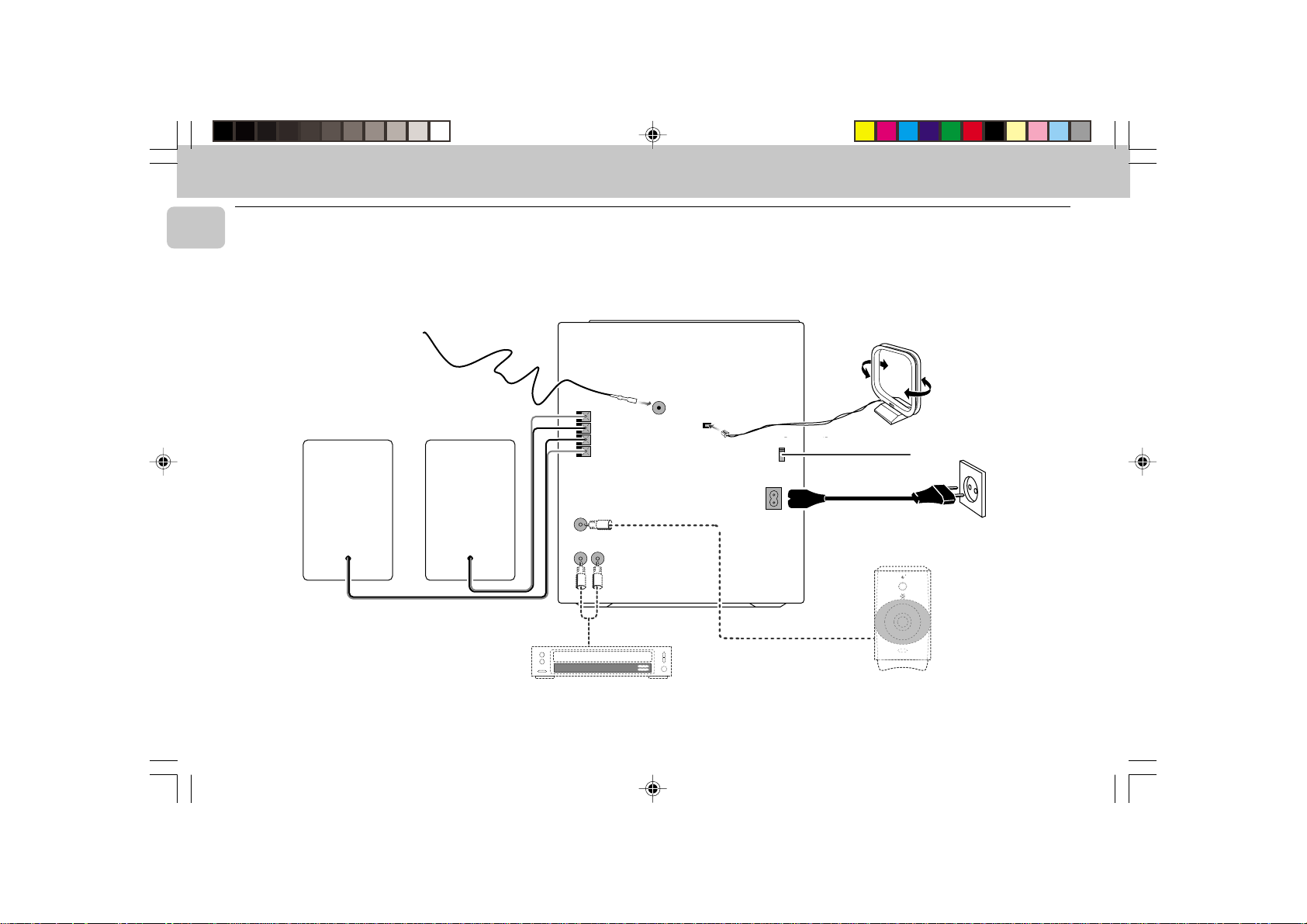
Rear Connections
B
+
R
–
–
L
LR
+
SUBWOOFER
FM AERIAL
75Ω
AM ANTENNA
VOLTAGE
VOLTAGE
SELECTOR
SELECTOR
220V-
110V-
127V
240V
220V-
110V-
240V
127V
AC
MAINS
OUT
~
A
F
G
AUX IN
STANDBY ON
V
E
L
E
R
L
E
C
F
O
O
N
O
T
W
R
O
B
L
U
S
MIN MAX
CUT OFF FREQUENCY
HIGH POWER SUBWOOFER
60Hz 150Hz
C
D
AUDIO OUT
6
E
pg 01-24/C30/21&/30-En 3/3/00, 4:23 PM6
3139 116 19351

PREPARATION
+
-
+
-
A AM Loop Antenna
Connection
Connect the supplied loop antenna to the
AM ANTENNA terminal. Place the AM loop
antenna far away from the system and
adjust its position for the best reception.
B FM Wire Antenna
Connection
Connect the supplied FM wire antenna to
the FM AERIAL (FM ANTENNA) 75 Ω
terminal. Adjust the position of the FM
antenna for the best reception.
Outdoor Antenna
For better FM stereo reception, connect an
outdoor FM antenna to the FM AERIAL (FM
ANTENNA) 75 Ω terminal using a 75 Ω
coaxial wire.
FM AERIAL 75Ω
FM ANTENNA 75Ω
OR
C Speakers Connection
• Connect the right speaker to Front
terminal R, with the colored wire to +
and the black wire to -.
• Connect the left speaker to Front
terminal L, with the colored wire to +
and the black wire to -.
• Clip the stripped portion of the speaker
wire as shown.
12 mm
unlock lock
D Connecting other
equipment to your system
You can connect the audio left and right
OUT terminals of a TV, VCR, Laser Disc
player, DVD player or CD Recorder to the
AUX IN terminals at the rear of the system.
E Subwoofer Out Connection
Connect the optional active subwoofer to
the SUBWOOFER OUT terminal. The
subwoofer reproduces just the low bass
sound effect (e.g. explosions, the rumble of
spaceships, etc.). Be sure to follow the
instructions supplied with the subwoofer.
F Adjusting the Operating
Voltage
(not available for version /30)
Before connecting the AC power cord to
the wall outlet, make sure that the voltage
selector at the rear of the system is set to
the local power line voltage. If not, reset
the selector before connecting to the wall
outlet.
G AC Power Supply
After all other connections have been
made, connect the AC power cord to the
system and to the wall outlet.
Inserting batteries into the
Remote Control
• Insert the batteries (Type R06 or AA)
into the remote control as shown in the
battery compartment.
• To avoid damage from possible battery
leakage, remove dead batteries or
batteries that will not be used for a long
time. For replacement, use type R06 or
AA batteries.
English
7
pg 01-24/C30/21&/30-En 3/3/00, 4:23 PM7
3139 116 19351
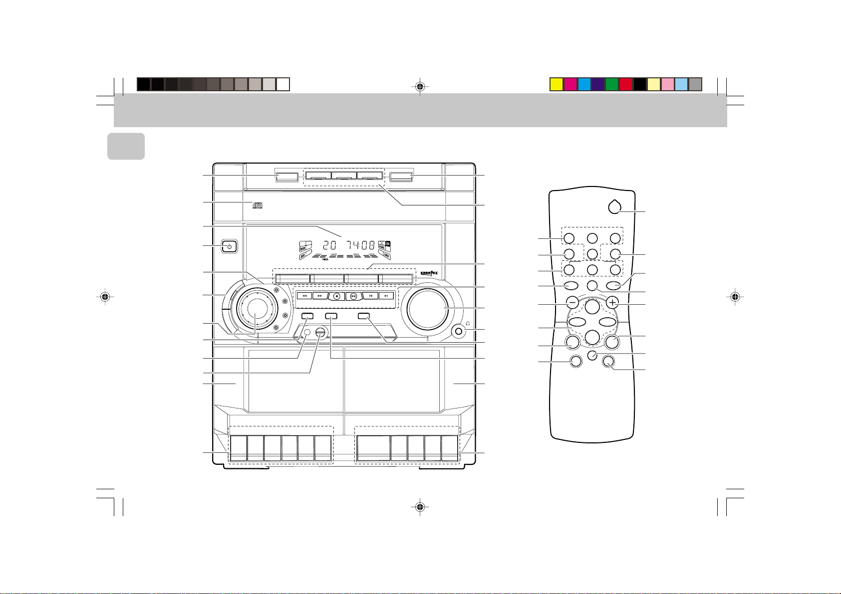
CONTROLS
3 CD ROTARY CHANGER SYSTEM
CD REWRITABLE COMPATIBLE
CD SYNCHRO RECORDING
English
8
7
6
1
3
5
4
2
™
¡
)
(
STANDBY-ON
B
D
TAPE 1
PLAY/REC
DISC 2
DISC CHANGE
DC
3
CHANGER
MINI HIFI SYSTEM
FW-
C10
JOG
CONTROL
B
R
OPTIMAL
JAZZ
ROCK
TECHNO
E
C
O
R
D
P
L
A
Y
▲
▲
▲
DISC 1
CD 1 • 2 • 3 BAND
▲▲▲
▲
TUNING
SEARCH
STOP•CLEAR
PROGRAM CLOCK•TIMER DIM
MICROPHONE - LEVEL
FULL AUTO STOP
.
▲
▲
S
T
O
P
O
P
E
N
P
A
U
S
E
SOUND NAVIGATION - JOG
DISC 3
TAPE 1 • 2
TAP ECD TUNER
▲
PRESET
PLAY• PAUSE PREV NEXT
Y
A
L
▲
P
▲
OPEN•CLOSE
3 CD ROTARY CHANGER SYSTEM
CD REWRITABLE COMPATIBLE
CD SYNCHRO RECORDING
VIDEO
AUX
▲
VOLUME
▲
▲
▲
•
•
•
TAPE 2
PLAYBACK
.
E
S
U
A
P
N
E
P
O
P
O
T
S
▲
9
0
!
@
#
$
%
^
&
*
!
%
0
£
#
@
@
4
CD DIRECT
PAUSE
REPEAT
VOLUME
É
í
Ç
à
MUTE
DSC DBB
2
TUNERTAPE 1/2CD
SLEEP AUXDIM
≥
§
21
3
SHUFFLE
Å
∞
@
#
ë
á
@
≤
5
8
pg 01-24/C30/21&/30-En 3/3/00, 4:23 PM8
3139 116 19351
 Loading...