


Philips FW-D596 User Manual

DVD Mini Hi-Fi System
FW-
D596
FW-
D596

Manufactured under license from Dolby Laboratories.
“Dolby”, “Pro-logic” and the double-D symbol are trade-
marks of dolby Laboratories.
MANUFACTURED UNDER LICENSE FROM DIGITAL
THEATER SYSTEMS, INC. US PAT. NO 5,451,942,
5,956,674, 5,974,380, 5,978,762 AND OTHER WORLD-
WIDE PATENTS ISSUED AND PENDING. “DTS” AND “DTS
DIGITAL SURROUND” ARE RESISTERED TRADEMARKS
OF DIGITAL THEATER SYSTEMS, INC. COPYRIGHT 1996,
2000 DIGITAL THEATER SYSTEMS, INC. ALL RIGHTS
RESERVED.
This product incorpporates copyright protection technol-
ogy that is protected by method claims of certain U.S.
patents and other intellectual property rights owned by
Macrovision Corporation and other rights owners. Use of
this copyright protection technology must be authorized
by Macrovision Corporation, and is intended for home and
other limited viewing uses only unless otherwise autho-
rized by Macrovision Corporation. Reserve engineering or
disassembly is prohibited.
2
5
4
3
2
1
º
ª
•
27
§
∞
24
£
(
6
7
8
9
-
-
-
0
1 2-3
!
M
A
R
G
O
R
P
@
#
$
%
^
&
(
™
¡
3
*
)
3
PLUG & PLAY
4
-for tuner installation
1

Index
English ------------------------------------------------ 6
Français -------------------------------------------- 49
Español --------------------------------------------- 92
------------------------------------------------------ 135
English
Français
Español
CAUTION
Use of controls or adjustment or
performance of procedures other
than herein may result in hazardous
radiation exposure or other unsafe
operation.
5

Contents
English
General Information/
Maintenance
Features .................................................................. 8
Discs for playback ................................................ 8
Region codes
Supplied accessories ............................................ 8
Environmental information ................................ 9
Care and safety information .............................. 9
Connections
Step 1: Placing the speakers and subwoofer 10
Step 2: Connecting speakers and subwoofer 10
Step 3: Connecting TV set ......................... 11~12
Using Video In jack (CVBS)
Using Component Video In jack (Pr Pb Y)
Using S-Video In jack
Using an accessory RF modulator
Step 4: Connecting FM/MW antennas ........... 13
Step 5: Connecting the power cord............... 13
Connecting a VCR or cable/satellite box ...... 14
Connecting digital audio equipment .............. 14
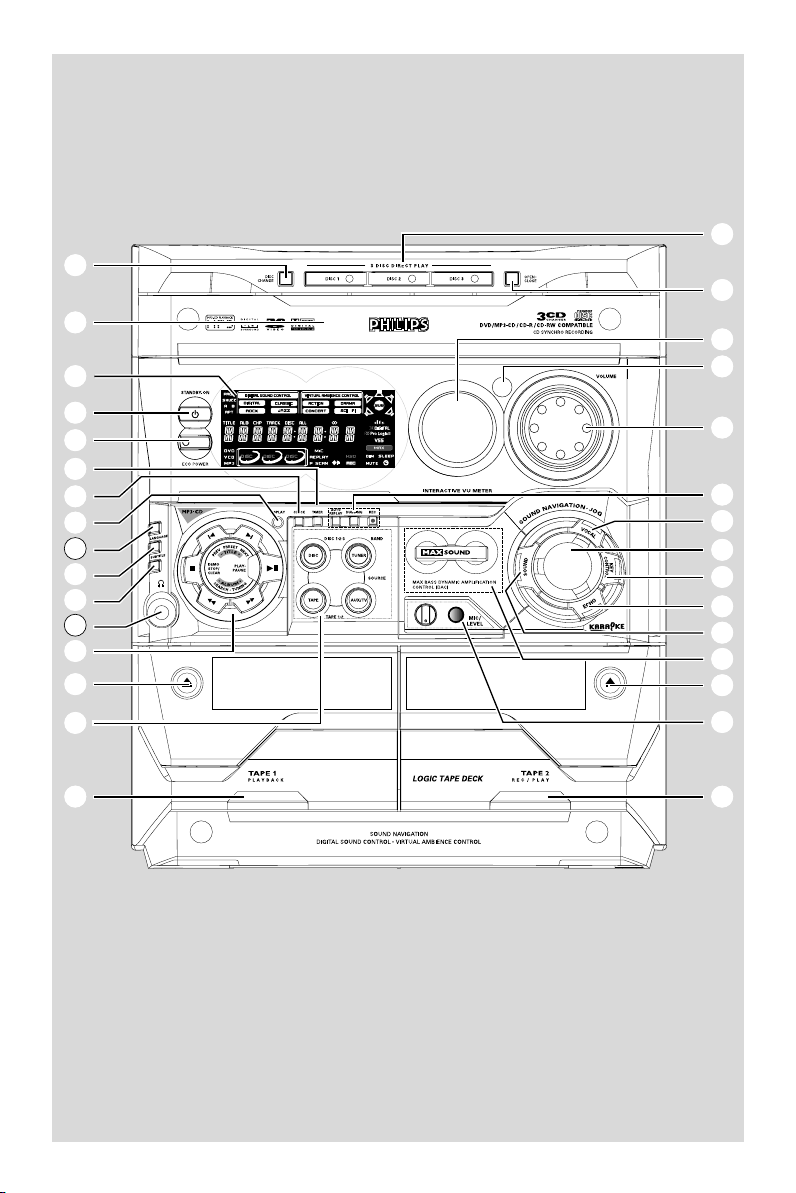
Functional Overview
Controls on the system ............................. 15~16
Remote control .................................................. 17
Basic Functions
Plug and Play (for tuner installation) .............. 18
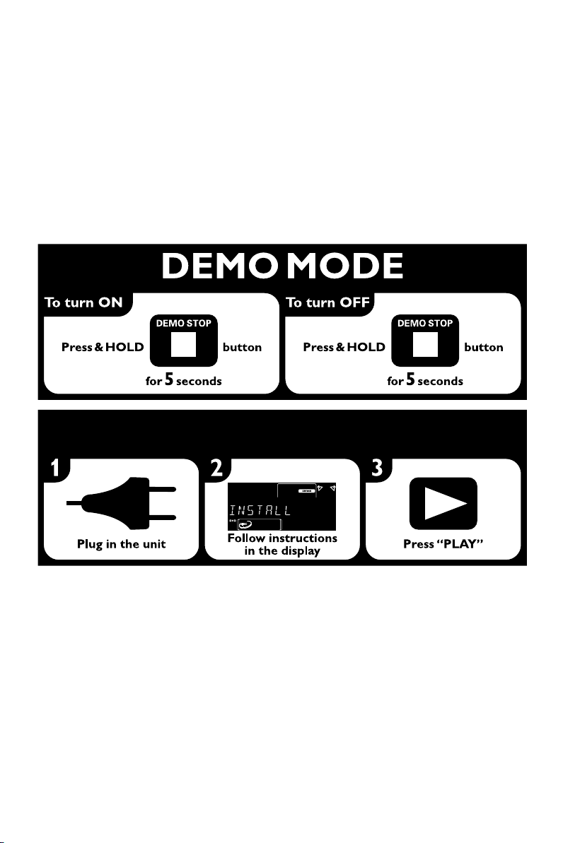
Demonstration mode ........................................ 18
Disc Operations
Playing discs ......................................................... 22
Using the disc menu .......................................... 22
Basic playback controls ..................................... 23
Skipping to another title (track)/chapter
Fast search
Continuing playback from the last stop point
Selecting various mode functions ............ 23~24
Repeat play mode
Shuffle play mode
Repeating a section within a chapter/track
Programing favorite tracks ............................... 24
Using the menu bar to program ..................... 24
Changing discs during playback ....................... 25
Special DVD/VCD features....................... 25~27
Changing subtitle language
Changing sound track language
Playing in slow motion mode
Searching for a particular passage
Displaying the disc information during playback
Moving to another title (track) / chapter
Playing from a selected point
Zooming in
Viewing from another angle
Advancing by frames
Checking the contents of DVD
Special VCD/SVCD features ............................ 27
Playback control (PBC)
MP3 / Picture Disc Operations
Playing MP3/picture disc (Kodak, JPEG) ........ 28
Preparations
Step 1: Inserting batteries into the remote
control .................................................................. 19
Step 2: Setting the clock ................................... 19
Step 3: Setting the TV set ................................. 20
Step 4: Setting speakers .................................... 21
Step 5: Setting language preference ................ 21
6
DVD Menu Operations
Using the menu bar ........................................... 29
Using the setup menu ................................ 30~34
Setting the TV shape
Setting the video out
Setting the screen saver
Setting the digital output
Setting the PCM output
Night mode - turning on/off
Test Tone - turning on/off
Changing the password
Restricting playback by setting parental level

Tuner Operations
Tuning to radio stations .................................... 35
Presetting radio stations ............................ 35~36
Automatic preset programming
Manual preset programming
Selecting a preset radio station ....................... 36
Deleting a preset radio station
Changing tuning grid .......................................... 36
Ta pe Operation/Recording
Ta pe playback ...................................................... 37
General information on recording ................. 37
Preparation for recording ................................ 38
Disc synchro recording..................................... 38
Dubbing tapes ..................................................... 38
Clock/Timer Operations
Viewing clock ...................................................... 39
Setting the timer ................................................. 39
Setting the sleep timer ...................................... 40
Sound and Volume Controls
Sound control ..................................................... 41
Selecting surround sound
MAX sound
Selecting sound effect
Volume control ................................................... 42
Changing the volume level
Switching off the volume temporarily
Listening through headphones
Contents
English
Other Functions
Switching on/off .................................................. 43
Switching the system on
Switching the system to standby mode
Switching to eco power standby mode
Power saving automatic standby
Dimming the display .......................................... 43
Vocal ...................................................................... 43
Key control .......................................................... 44
Echo ....................................................................... 44
Karaoke ................................................................ 44
Listening to external sources .......................... 44
Specifications ........................................... 45
Tr oubleshooting ............................. 46~47
Glossary ......................................................... 48
7

General Information
3
ALL
English
Features
Your DVD Mini Hi-Fi System with 2-channel full
digital amplifier creates the same dynamic sound
qualities that you find in full-fledged cinemas and
incorporates some of the best features in home
theater technology.
Other features include:
Built-in DTS and Dolby Digital decoder,
supporting virtual surround and stereo.
Additional Component Connections
Lets you connect other audio and audio/visual
components to the system so you can use the
system’s surround sound speakers.
Night mode
Lets you compress the dynamic range, reducing
the difference in loudness between different
sounds in Dolby Digital mode.
Parental control (rating level)
Lets you set a rating level so that your children
cannot watch a DVD that has a rating higher
than you set.
Sleep timer
Enables the system to switch to standby mode
automatically at a preset time.
Discs for playback
Your DVD Mini Hi-Fi System will play:
– Digital Video Discs (DVDs)
– Video CDs (VCDs)
–Super Video CDs (SVCDs)
– Digital Video Discs + Rewritable (DVD+RW)
– Compact Discs (CDs)
– Picture (Kodak, JPEG) files on CDR(W)
– Supported MP3-CD format.
• ISO 9660 / UDF format
• Max. title/album name –12 characters
• Max. title number plus album is 255.
• Max. nested directory is 8 levels.
• The max. album number is 32.
• The max. MP3 track number is 999.
• Supported sampling frequencies for MP3 disc:
32 kHz, 44.1 kHz, 48 kHz.
• Supported Bit-rates of MP3 disc are: 32, 64,
96, 128, 192, 256 (kbps).
– Following formats can’t be supported
• The files like *.VMA, *.AAC, *.DLF, *.M3U,
*.PLS, *.WAV, *.WMA
• Non-English Album/Title name
• The discs recorded under Joliet format
• MP3 Pro and MP3 with ID3 tag
Region codes
DVDs must be labeled for ALL regions or for
Region 3 in order to play on this system. You
cannot play discs that are labeled for other
regions.
Notes:
–For mixed mode discs, only one mode will be
selected for playback according to the recording
format.
– If you are having trouble playing a certain disc,
remove the disc and try a different one. Improperly
formatted discs will not play on this system.
Supplied accessories
– Composite video cable (yellow)
– Component video cables
(red/blue/green)
– Audio cables (white, red)
– FM wire antenna
– MW loop antenna
– Remote Control and
two AA batteries
–AC power cable
– Din Out cable
– This instruction booklet and a Quick Use Guide
8

General Information/Maintenance
CBABC
Environmental information
Any unnecessary packaging has been omitted.
We have tried to make the packaging easy to
separate into three materials: cardboard (box),
polystyrene foam (buffer) and polyethylene (bags,
protective foam sheet).
Your system consists of materials which can be
recycled and reused if disassembled by a
specialised company. Please observe the local
regulations regarding the disposal of packaging
materials, exhausted batteries and old
equipment.
Care and safety information
Avoid high temperatures, moisture,
water and dust
● Do not expose the system, batteries or discs to
humidity, rain, sand or excessive heat (caused by
heating equipment or direct sunlight). Always
keep disc trays closed to avoid dust buildup on
the lens.
● No objects filled with liquids, such as vases, shall
be placed on the apparatus.
● No naked flame sources, such as lighted candles,
should be placed on the apparatus.
Avoid condensation problem
● The lens may cloud over when the player is
suddenly moved from cold to warm
surroundings, making it impossible to play a disc.
Leave the player in the warm environment until
the moisture evaporates.
Do not block the vents
● Do not operate the system in an enclosed
cabinet and allow about 10 cm (4 inches) of free
space all around the player for adequate
ventilation.
● The ventilation should not be impeded by
covering the ventilation openings with items, such
as newspapers table-cloths, curtains, etc.
Cleaning the cabinet
● Use soft cloth slightly moistened
with a mild detergent solution.
Do not use a solution containing
alcohol, spirits, ammonia or
abrasives.
Cleaning discs
● To clean a CD, wipe it in a
straight line from the center towards the edge
using soft and lint-free cloth. A cleaning agent
may damage the disc.
● Write only on the printed side of a CDR(W)
and only with a soft felt-tipped pen.
● Handle the disc by its edge. Do not touch the
surface.
Cleaning the disc lens
● After prolonged use, dirt or dust may accumulate
at the disc lens. To ensure good playback quality,
clean the disc lens with Philips CD Lens Cleaner
or any commercially available cleaner. Follow the
instructions supplied with cleaner.
Finding a suitable location
● Place the player on a flat, hard, stable surface.
Cleaning the head and the tape paths
● To ensure good recording and playback quality,
clean the head A, the capstan(s) B, and
pressure roller(s) C after every 50 hours of tape
operation.
● Use a cotton swab slightly moistened with
cleaning fluid or alcohol.
● You also can clean the head by playing a cleaning
tape once.
English
10 cm
(4 inches)
10 cm
(4 inches)
DVD Mini Hi-Fi System
10 cm
(4 inches)
Demagnetising the head
● Use a demagnetising tape available at your dealer.
9

Connections
4
English
Step 1: Placing the speakers and
subwoofer
Step 2: Connecting speakers and
subwoofer
Center Speaker
speaker
(right)
Right Speaker
DIN OUT
SUBWOOFER
OUT
SPEAKERS 4
Subwoofer
Left Speaker
speaker
(left)
For best possible surround sound, all speakers
(except subwoofer) should be placed at the
same distance from the listening position.
● Place the front left and right speakers at equal
distances from the TV set and at an angle of
approximately 45 degrees from the listening
position.
● Place the center speaker above the TV set or the
system so the center channel’s sound is localized.
● Place the surround speakers at normal listening
ear level facing each other or mounted on the
set.
● Place the subwoofer on the floor near the TV
set.
Notes:
–To avoid magnetic interference, do not position
the front speakers too close to your TV set.
– Allow adequate ventilation around the DVD Mini
Hi-Fi System.
IMPORTANT!
The type plate is located on the rear of
the system.
To avoid overheating of the system, a
safety circuit has been built in. Therefore,
your system may switch to Standby
mode automatically under extreme
conditions. If this happens, let the system
cool down before reusing it.
● Connect the speaker wires to the SPEAKERS
(FRONT) terminals, right speaker to “R” and left
speaker to “L”, coloured (marked) wire to “+”
and black (unmarked) wire to “–”. Fully insert
the stripped portion of the speaker wire into the
terminal as shown.
● Connect the Surround Speakers and Center
Speaker system using the supplied speaker cables
to the speaker jacks on the SUBWOOFER by
matching the colours of the jacks and speaker
plugs.
● Connect the Subwoofer using the supplied
speaker cable to the DIN OUT jack on the DVD
Mini Hi-Fi System.
● Connect the AC MAINS.
Speakers
Front Left (L)
Front Right (R)
Center
Surround (Rear) Left (L)
Surround (Rear) Right (R)
––––
Black
Black
Black
Black
Black
White
Green
Blue
Grey
Notes:
–For optimal sound performance, use the
supplied speakers.
– Do not connect more than one speaker to any
one pair of +/- speaker terminals.
– Do not connect speakers with an impedance
lower than the speakers supplied. Please refer to
the SPECIFICATIONS section of this manual.
+
Red
10
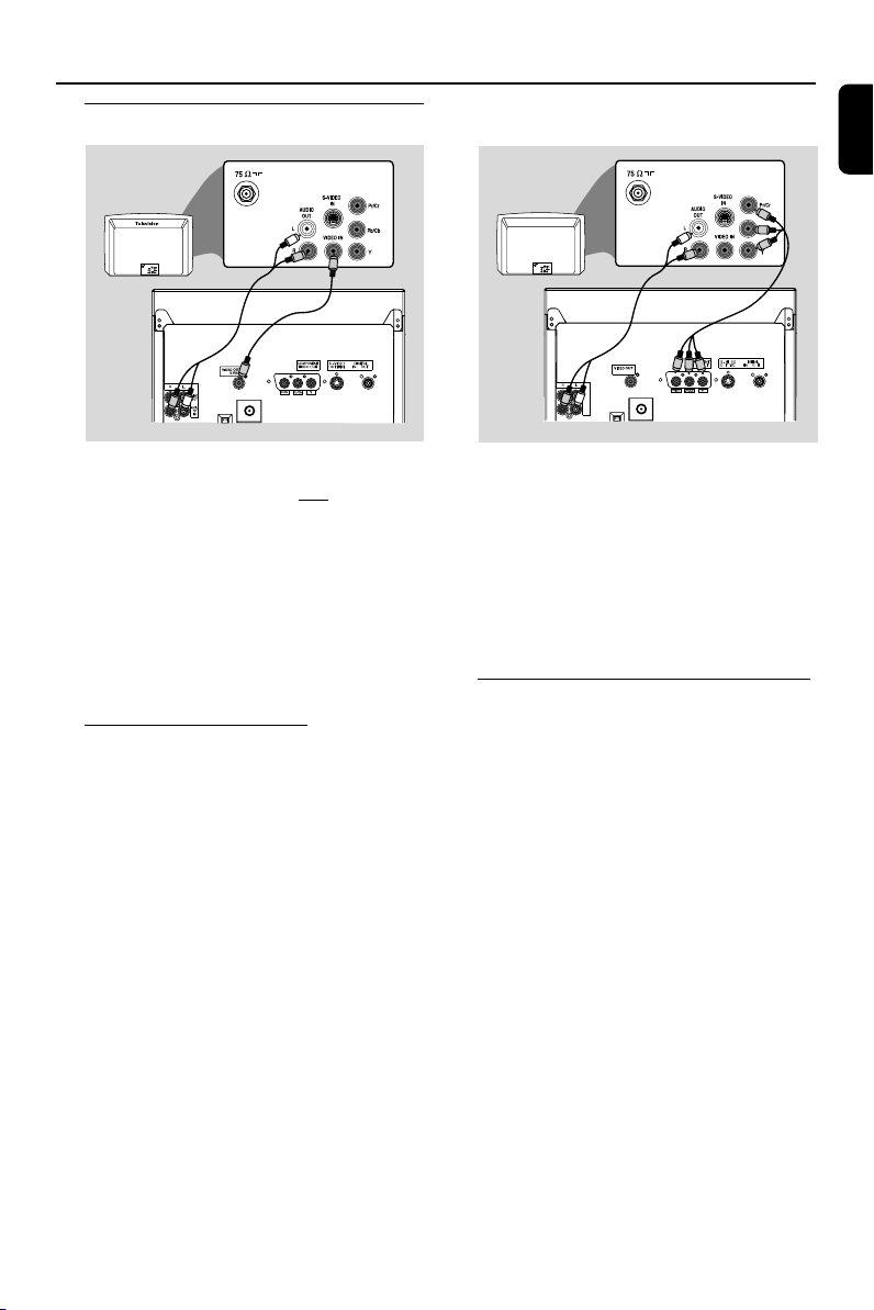
Step 3: Connecting TV set
Television
Y
AUX/
TV
IN
LINE
OUT
(CVBS)
D
D
D
P
U
UU
(
(
Connections
English
IMPORTANT!
–You only need to make one video
connection from the following options,
according to the capabilities of your TV
system.
– S-Video or Component Video
connection provides higher picture
quality. These options must be available
on your TV set.
– Connect the system directly to the TV
set.
Using Video In jack (CVBS)
● Use the composite video cable (yellow) to
connect the system’s CVBS jack to the video
input jack (or labeled as A/V In, Video In,
Composite or Baseband) on the TV set.
● To listen to TV channels through this system, use
the audio cables (white/red) to connect AUX/
TV IN (L/R) jacks to the corresponding
AUDIO OUT jacks on the TV set.
IMPORTANT!
– If both S-Video and Component (Pr
Pb Y) Video connections are used to
connect to your TV set, the Video signal
will automatically switch to S-Video
when you power up the system. To set
the VIDEO OUT (put) to ‘Pr Pb Y’, see
page 31, Using the Setup Menu – Setting
the video out.
Using component Video In jack (Pr Pb Y)
● Use the component video cables (red/blue/
green) to connect the system’s Pr Pb Y jacks to
the corresponding Component video input jacks
(or labeled as Pr/Cr Pb/Cb Y or YUV) on the TV
set.
● To listen to TV channels through this system, use
the audio cables (white/red) to connect AUX/
TV IN (L/R) jacks to the corresponding
AUDIO OUT jacks on the TV set.
11

Connections
English
RF coaxial cable to TV
Television
Y
P
D
D
(
(
D
U
(CVBS)
LINE
OUT
AUX/
TV
IN
UU
IMPORTANT!
– If the picture is distorted, check the
Video Output setting. Make sure it is set
to ‘S-Video’. See page 31, Using the Setup
Menu – Setting the video out.
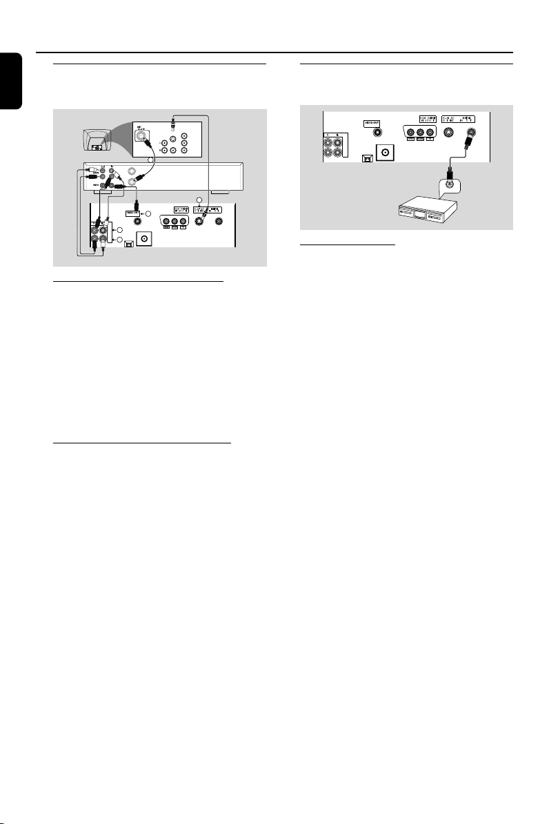
Using S-Video In jack
● Use the S-Video cable (not supplied) to connect
the system’s S-VIDEO OUT jack to the SVideo input jack (or labeled as Y/C or S-VHS) on
the TV set.
● To listen to TV channels through this system, use
the audio cables (white/red) to connect AUX/
TV IN (L/R) jacks to the corresponding
AUDIO OUT jacks on the TV set.
Back of RF Modulator
(example only)
AUDIO IN
TO TVINT IN
VIDEO
IN
R L
CH3 CH4
Antenna or
Cable TV signal
P
D
D
(
(
D
U
(CVBS)
LINE
OUT
UU
IMPORTANT!
– If your TV set only has a single
Antenna In jack (or labeled as 75 ohm or
RF In), you will need a RF modulator in
order to view the DVD playback via TV.
See your electronics retailer or contact
Philips for details on RF modulator
availability and operations.
Using an accessory RF modulator
● Use the composite cable (yellow) to connect the
system’s CVBS jack to the video input jack on
the RF modulator.
● Use the RF coaxial cable (not supplied) to
connect the RF modulator to your TV’s RF jack.
12

Connections
Step 4: Connecting FM/MW
antennas
FM
antenna
MW
antenna
fix the claw
into the slot
MW ANTENNA FM ANTENNA
DIN OUT
● Connect the supplied MW loop antenna to the
MW jack. Place the MW loop antenna on a
shelf or attach it to a stand or wall.
● Connect the supplied FM antenna to the FM
jack. Extend the FM antenna and fix its end to
the wall.
For better FM stereo reception, connect an
outdoor FM antenna to the FM ANTENNA
terminal.
MW ANTENNA FM ANTENNA
Step 5: Connecting the power
cord
DIN OUT
SUBWOOFER
OUT
COMPONENT
VIDEO IN
S-VIDEO
IN
Pr/Cr
AUDIO
OUT
~ AC MAINS
Pb/Cb
VIDEO IN
Y
After everything is connected properly,
plug in the AC power cord to the power
outlet.
Never make or change any connection with the
power switched on.
On the DVD Mini Hi-Fi System
“AUTO INSTALL-PRESS PLAY” may appear
on the display panel. Press 2; on the front panel
to search and store all available radio stations or
press 9 to exit (See page 35, Tuner OperationsPresetting radio stations).
If your system is equipped with a Voltage
Selector, set the VOLTAGE SELECTOR
to the local power line voltage.
Power Outlet
VOLTAGE
SELECTOR
110V127V
220V240V
NOT FOR ALL
VERSIONS
English
Notes:
– Adjust the position of the antennas for optimal
reception.
–Position the antennas as far as possible from
your TV set, VCR or other radiation sources to
prevent unwanted interference.
13
Connections
English
Connecting a VCR or
cable/satellite box
COMPONENT
VIDEO IN
S-VIDEO
IN
Pr/Cr
AUDIO
OUT
Pb/Cb
VIDEO IN
Y
1
ANT IN
VCR or
Cable/Satellite
TO TV
Box
P
D
U
3
(CVBS)
LINE
4
OUT
AUX/
TV
2
IN
Viewing and listening to playback
1 Connect the VCR or Cable/Satellite Box to the
TV system as shown.
2 Connect the system’s AUX/TV IN (R/L) jacks to
the AUDIO OUT jacks on the VCR or Cable/
Satellite box.
Before starting operation, press AUX/TV on
the remote control to select “AUX” in order to
activate the input source.
3
D
D
(
(
UU
Connecting digital audio
equipment
P
D
D
(
(
D
U
(CVBS)
LINE
OUT
AUX/
TV
IN
Recording (digital)
Connect the system’s DIGITAL OUT jack to the
DIGITAL IN jack on a digital recording device
(DTS-Digital Theater System compatible, with a
Dolby Digital decoder, for example).
Before operation, set the DIGITAL OUTPUT
according to the audio connection. (See page 31,
Using the Setup Menu – Setting the digital
output).
UU
DIGITAL IN
Using the VCR for recording DVDs
Some DVDs are copy-protected. You cannot
record or dub protected discs using a VCR.
3 Connect the system’s CVBS jack to the VIDEO
IN jack on the VCR.
4 Connect the system’s LINE OUT (R/L) jacks
to the AUDIO IN jacks on the VCR. This will
allow you to make analog stereo (two channel,
right and left) recording.
To view DVD playback while recording
You must connect the system to your TV system
using the S-VIDEO (as shown above) or the
Component (Pr Pb Y) video connection.
14

Functional Overview
Controls on the system
1 ECO POWER
– to switch the system on or to Eco Power
Standby mode.
2 STANDBY ON2
–to switch the system on or to Standby mode.
3 DISPLAY SCREEN
– to view the current status of the system.
4 DISC TRAYS
5 DISC CHANGE
– to change disc(s).
6 DISC 1 / DISC 2 / DISC 3
– to select a disc tray for playback.
7 OPEN•CLOSE
– to open or close the disc tray.
8 INTERACTIVE VU METER
– to show the VU (volume unit) meter in music or
volume mode depending on the display mode
selected.
9 SENSOR
– point the remote control towards this sensor.
0 VOLUME
– to increase or decrease the volume.
! Ta pe Deck Operation
AUTO REPLAY
–to select continuous playback in either AUTO
PLAY or ONCE mode only.
DUBBING
– to dub a tape.
REC
– to start recording on tape deck 2.
@ VOCAL
– to fade out the original vocal from Karaoke or to
switch between mono or stereo mode during
audio disc playback.
# JOG CONTROL
– to select the desired sound effect for the
selected sound feature.
$ KEY CONTROL
– to change the tone level to suit your vocal range.
I .................to decrease the key tone level.
.................to restore the key tone level to
original setting.
i .................to increase the key tone level.
% ECHO
– to adjust the echo level for karaoke after
inserting the microphone.
^ SOUND
– to activate or deactivate the surround sound
effect.
& MAX SOUND (MAX)
– to activate or deactivate the optimal mix of
various sound features.
* MIC/LEVEL
– to connect microphone jack.
– to adjust the mixing level for karaoke or
microphone recording.
( 0
– to open the tape deck door.
) TAPE DECK 1
¡ TAPE DECK 2
™ SOURCE
– to select the following:
DISC (DISC 1•2•3)
– to select disc tray 1, 2 or 3
TUNER (BAND)
– to select waveband: FM or MW.
TAPE (TAPE 1-2)
– to select tape deck 1 or 2.
AUX/TV
– to select a connected external source: TV/CDR
or AUX (auxiliary) mode.
£ Mode Selection
PLAY/PAUSE 38
for DISC .................... to start or interrupt playback.
for TAPE..................... to start playback.
for PLUG&PLAY ...(on the system only) to initiate
plug & play mode.
SEARCH•TUNING 1 ¡
(ALBUM – / +)
for DISC .................... to search backward/forward.
for TAPE..................... to rewind or fast forward.
for TUNER ............... to tune to a lower or higher
radio frequency.
for CLOCK ..............(in standby mode)to set the
minute and hour.
DEMO STOP/CLEAR 7
for DISC .................... to stop playback or to clear a
programme.
for DEMO ................(in Standby or ECO power
mode) to activate/deactivate
demonstration.
for PLUG&PLAY ...(on the system only) to exit
plug&play mode.
English
15
 Loading...