


Philips FW-C399 User Manual
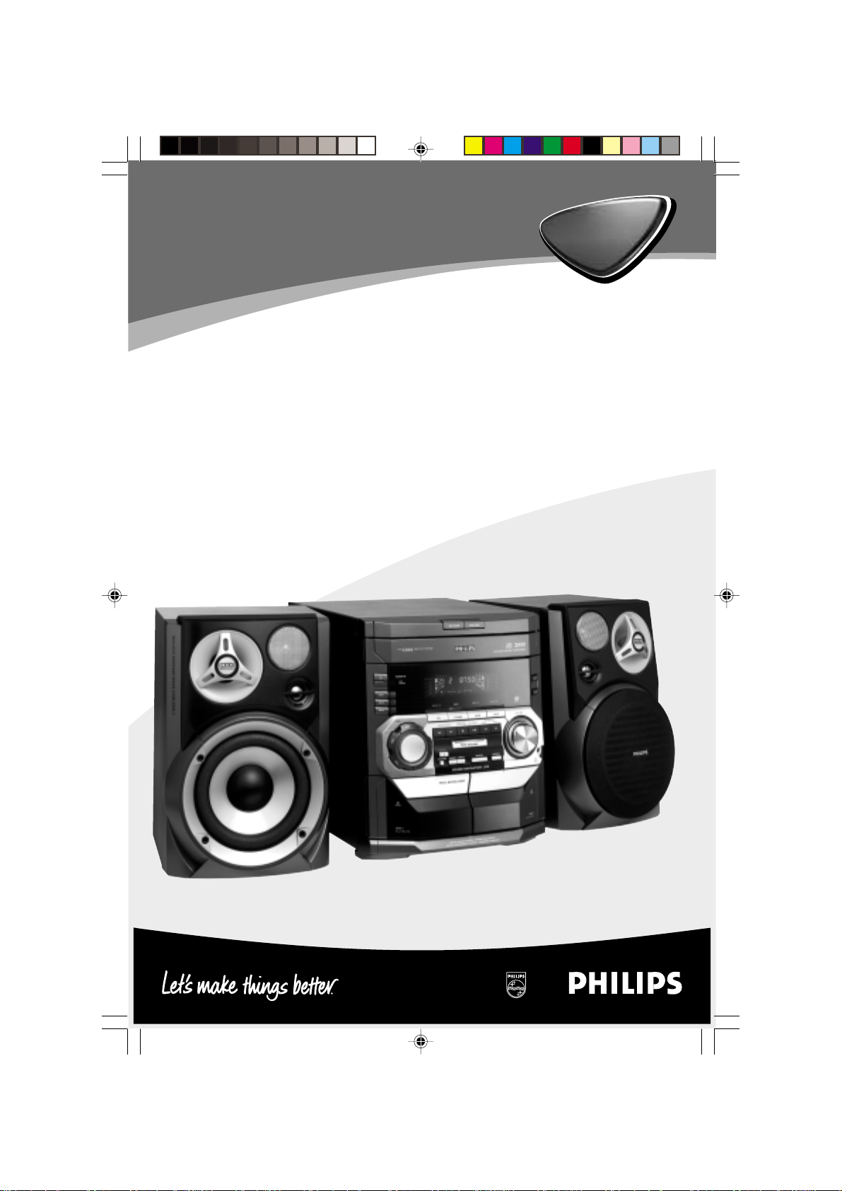
Mini Hi-Fi System
FW-
C399
FW-
C399
pg 001-030/C399/22-Eng 1/29/02, 5:55 PM1
1
3139 115 21221
Important notes for users in the
U.K.
Mains plug
This apparatus is fitted with an approved 13
Amp plug. To change a fuse in this type of plug
proceed as follows:
1 Remove fuse cover and fuse.
2 Fix new fuse which should be a BS1362 5 Amp,
A.S.T.A. or BSI approved type.
3 Refit the fuse cover.
If the fitted plug is not suitable for your socket
outlets, it should be cut off and an appropriate
plug fitted in its place.
If the mains plug contains a fuse, this should
have a value of 5 Amp. If a plug without a fuse
is used, the fuse at the distribution board
should not be greater than 5 Amp.
Note: The severed plug must be disposed of to
avoid a possible shock hazard should it be
inserted into a 13 Amp socket elsewhere.
How to connect a plug
The wires in the mains lead are coloured with
the following code: blue = neutral (N),
brown = live (L).
¶ As these colour s may not correspond with the
colour markings identifying the terminals in
your plug, proceed as follows:
– Connect the blue wire to the terminal
marked N or coloured black.
– Connect the brown wire to the terminal
marked L or coloured red.
– Do not connect either wire to the earth
terminal in the plug, marked E (or e) or
coloured green (or green and yellow).
Before replacing the plug cover, make certain
that the cord grip is clamped over the sheath
of the lead - not simply over the two wires.
Italia
DICHIARAZIONE DI CONFORMITA’
Si dichiara che l’apparecchio FW-C399 Philips
risponde alle prescrizioni dell’ar t. 2 comma 1 del
D.M. 28 Agosto 1995 n. 548.
Fatto a Eindhoven
Philips Consumer Electronics
Philips, Glaslaan 2
5616 JB Eindhoven, The Netherlands
Norge
Typeskilt finnes på apparatens underside.
Observer: Nettbryteren er sekundert
innkoplet. Den innebygde netdelen er
derfor ikke frakoplet nettet så lenge
apparatet er tilsluttet nettkontakten.
For å redusere faren for brann eller elektrisk
støt, skal apparatet ikke utsettes for regn eller
fuktighet.
CAUTION
Use of controls or adjustments or
performance of procedures other than
herein may result in hazardous
radiation exposure or other unsafe
operation.
Copyright in the U.K.
Recording and playback of material may
require consent. See Copyright Act 1956 and
The Performer’s Protection Acts 1958 to 1972.
2
pg 001-030/C399/22-Eng 1/29/02, 5:55 PM2
3139 115 21221
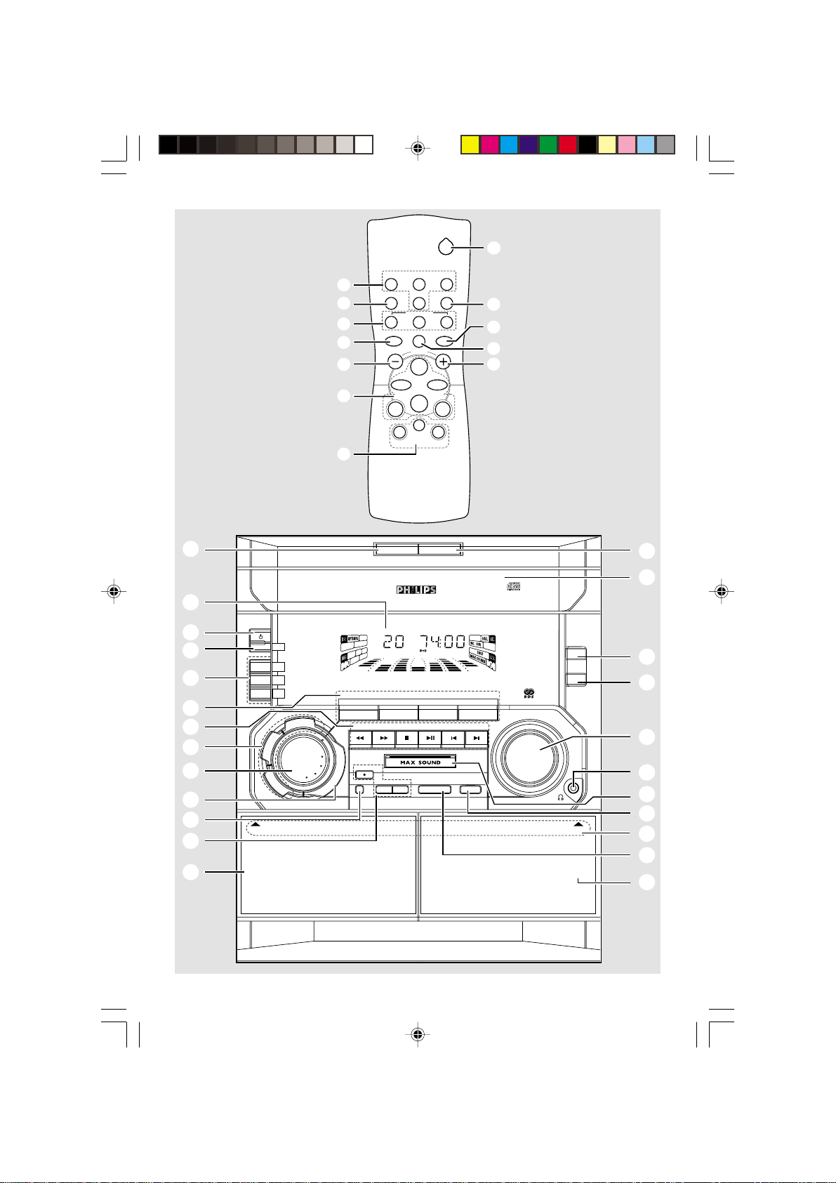
2
•
£
≤
1
2
3
4
5
6
7
8
9
0
!
CD DIRECT
21
SLEEP
VOLUME
É
Å
Ç
DBB 1/2/3
SHUFFLE
ë
TUNERTAPE 1/2CD
MAXAUXINC.SURR.
^
3
≥
§
*
á
4
8
3
∞
*
5
REPEAT
í
à
DSC VEC
7
DISC CHANGE
MINI HIFI SYSTEMFW-
STAND BY -O N
ECO
POWER
DISC 1
DISC 2
DISC 3
JOG
B
B
D
C
S
D
C
E
V
OPEN OPEN
N
I
MUTE DIM
CD1 • 2 • 3 BAND
CD TUNER TAPE AUX
SEARCH•TUNING
D
N
U
O
R
R
U
RECORD
S
E
L
B
I
D
CLOCK•TIMER DUBBINGA. REPLAY PROGRAM
E
R
C
SOUND NAVIGATION - JOG
DEMO STOP
PLAY• PAUSE PREV NEXT
STOP•CLEAR
OPEN•CLOSE
TAPE 1 • 2
DIM MODE
CD/CD-R/CD-RW COMPATIBLE
VIDEO/CDR
▲
PRESET
▲
3
VOLUME
CHANGER
DC
RDS
NEWS
TAPE 2TAPE 1
™
¡
)
(
*
&
^
%
$
#
@
3
pg 001-030/C399/22-Eng 1/29/02, 5:55 PM3
3
3139 115 21221
DK
Advarsel: Usynlig laserstråling ved åbning
når sikkerhedsafbrydere er ude af funktion.
Undgå utsættelse for stråling.
Bemærk: Netafbryderen er sekundært
indkoblet og ofbryder ikke strømmen fra
nettet. Den indbyggede netdel er derfor
tilsluttet til lysnettet så længe netstikket
sidder i stikkontakten.
S
Klass 1 laseraparat
Varning! Om apparaten används på annat
sätt än i denna bruksanvisning specificerats,
kan användaren utsättas för osynlig
laserstrålning, som överskrider gränsen för
laserklass 1.
Observera! Stömbrytaren är sekundärt
kopplad och bryter inte strömmen från
nätet. Den inbyggda nätdelen är därför
ansluten till elnätet så länge stickproppen
sitter i vägguttaget.
SF
Luokan 1 laserlaite
Varoitus! Laitteen käyttäminen muulla
kuin tässä käyttöohjeessa mainitulla tavalla
saattaa altistaa käyttäjän
turvallisuusluokan 1 ylittävälle
näkymättömälle lasersäteilylle.
Oikeus muutoksiin varataan. Laite ei
saa olla alttiina tippu-ja roiskevedelle.
Huom. Toiminnanvalitsin on kytketty
toisiopuolelle, eikä se kytke laitetta irti
sähköverkosta. Sisäänrakennettu verkkoosa on kytkettynä sähköverkkoon aina
silloin, kun pistoke on pistorasiassa.
4
pg 001-030/C399/22-Eng 1/29/02, 5:55 PM4
3139 115 21221
Index
English ------------------------------------------------ 6
Français -------------------------------------------- 31
Español --------------------------------------------- 56
Deutsch --------------------------------------------- 81
Nederlands -------------------------------------- 107
Italiano -------------------------------------------- 132
English
Français
Español
DeutschNederlandsItalianoSvenskaDanskSuomi
pg 001-030/C399/22-Eng 1/29/02, 5:55 PM5
Svenska ------------------------------------------- 157
Dansk --------------------------------------------- 182
Suomi --------------------------------------------- 207
Português ---------------------------------------- 232
Português
∂ППЛУИО¿ ----------------------------------------- 257
∂ППЛУИО¿Polski
5
3139 115 21221
Contents
English
General Information
Supplied accessories ............................................ 7
Acknowledgement ............................................... 7
Environmental information ................................ 7
Safety information ................................................ 7
Preparations
Rear connections ............................................. 8–9
Optional connection ........................................... 9
Inserting batteries into the remote
control .................................................................... 9
Controls
Controls on the system and remote
control ........................................................... 10–11
Power
Antennas connection
Speakers connection
Connecting other equipment to your system
Radio Reception
Tuning to radio stations .................................... 19
Storing preset radio stations .................... 19–20
Automatic preset programming
Manual preset programming
Tuning to preset radio stations ....................... 20
RDS ................................................................ 20–21
Setting the RDS clock
NEWS ................................................................... 21
Tape Operation/Recording
Loading tape ........................................................ 22
Playing tapes ........................................................ 23
Rewinding/Fast forwarding ............................... 23
General information on recording ................. 23
Preparation for recording ................................ 24
One touch recording......................................... 24
CD Synchronised start recording .................. 24
Dubbing tapes ..................................................... 24
Basic Functions
Plug and Play ........................................................ 12
Demonstration mode ........................................ 13
Switching the system on ................................... 13
Switching the system to standby mode ........ 13
Switching the system to Eco Power
standby mode ...................................................... 13
Dim mode ............................................................ 13
Volume control ................................................... 14
Sound navigation.......................................... 14–15
MAX sound
VEC (Victual Environment Control)
DSC (Digital Sound Control)
DBB (Dynamic Bass Boost)
Incredible Surround
CD Operation
Discs for playback .............................................. 16
Loading discs ....................................................... 16
Playing discs ......................................................... 17
Selecting a desired track/passage .................... 17
Replacing discs during playback ...................... 17
Repeat and Shuffle .............................................. 17
Repeat play
Random play
Programming the disc tracks ........................... 18
Erasing the programme ..................................... 18
Clock/Timer
View clock ............................................................ 25
Clock setting ....................................................... 25
Timer setting ....................................................... 26
Deactivating the timer
Activating the timer
Sleep timer setting ...................................... 26–27
External Sources
Listening to external sources .......................... 27
Specifications ........................................... 28
Maintenance.............................................. 29
Troubleshooting ............................. 29–30
6
pg 001-030/C399/22-Eng 1/29/02, 5:55 PM6
3139 115 21221
General Information
This product complies with the radio
interference requirements of the European
Community.
Supplied accessories
– 2 speaker boxes
– remote control
– batteries (two AA size) for remote control
– AM loop antenna
– FM wire antenna
– AC power cord
Acknowledgement
Energy Star
As an ENERGY STAR
Partner, Philips has
determined that this product
meets the ENERGY STAR
guidelines for energy efficiency.
R
R
Environmental information
All unnecessary packaging has been omitted. We
have tried to make the packaging easy to
separate into three materials: cardboard (box),
polystyrene foam (buffer) and polyethylene (bags,
protective foam sheet).
Your system consists of materials which can be
recycled and reused if disassembled by a
specialised company. Please observe the local
regulations regarding the disposal of packaging
materials, exhausted batteries and old
equipment.
Safety information
● Before operating the system, check that the
operating voltage indicated on the typeplate (or
the voltage indication beside the voltage
selector) of your system is identical with the
voltage of your local power supply. If not, please
consult your dealer.
● Place the system on a flat, hard and stable
surface.
● Place the system in a location with adequate
ventilation to prevent internal heat build-up in
your system. Allow at least 10 cm (4 inches)
clearance from the rear and the top of the unit
and 5 cm (2 inches) from each side.
● Do not expose the system, batteries or discs to
excessive moisture, rain, sand or heat sources
caused by heating equipment or direct sunlight.
● The lens may cloud over when the system is
suddenly moved from cold to warm
surroundings, making it impossible to play a disc.
Leave the system in the warm environment until
the moisture evaporates.
● The mechanical par ts of the set contain self-
lubricating bearings and must not be oiled or
lubricated.
● When the system is switched to Standby
mode, it is still consuming some power.
To disconnect the system from the
power supply completely, remove the AC
power plug from the wall socket.
English
pg 001-030/C399/22-Eng 1/29/02, 5:55 PM7
7
3139 115 21221
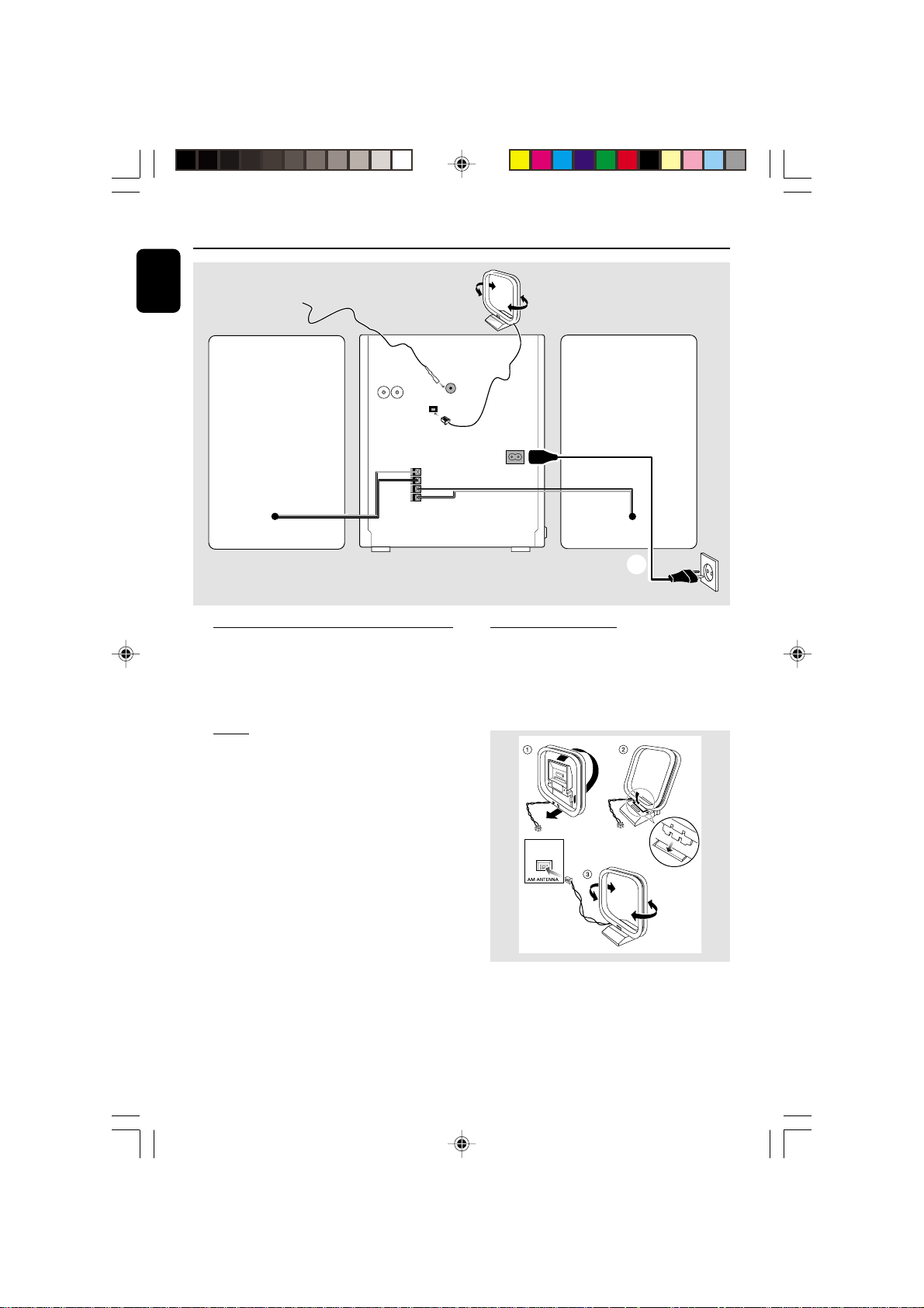
Preparations
Fix the claw
to the slot
English
FM wire antenna
AUX/
CDR
IN
LR
speaker
AM ANTENNA
(right)
C
+
R
—
—
L
+
SPEAKERS 6Ω
Rear connections
The type plate is located at the rear of the
system.
For users in the U.K.: please follow the
instructions on page 2.
AM loop
antenna
FM AERIAL
75Ω
B
AC
MAINS
B Antennas Connection
Connect the supplied AM loop antenna and FM
antenna to the respective terminals. Adjust the
position of the antenna for optimal reception.
AM Antenna
speaker
(left)
A
AC power cord
A Power
Before connecting the AC power cord to the
wall outlet, ensure that all other connections
have been made.
WARNING!
– For optimal performance, use only the
original power cable.
– Never make or change any connections
with the power switched on.
To avoid overheating of the system, a safety
circuit has been built in. Therefore, your
system may switch to Standby mode
automatically under extreme conditions. If
this happens, let the system cool down
before reusing it (not available for all versions).
8
pg 001-030/C399/22-Eng 1/29/02, 5:55 PM8
● Position the antenna as far as possible from a TV,
VCR or other radiation source.
3139 115 21221
Preparations
1
2
FM Antenna
● For better FM stereo reception, connect an
outdoor FM antenna to the FM ANTENNA
terminal.
C Speakers Connection
Front Speakers
Connect the speaker wires to the SPEAKERS
terminals, right speaker to "R" and left speaker to
"L", coloured (marked) wire to "+" and black
(unmarked) wire to "-".
1
● Fully inser t the stripped portion of the speaker
wire into the terminal as shown.
Notes:
– For optimal sound performance, use the
supplied speakers.
– Do not connect more than one speaker to any
one pair of +/- speaker terminals.
– Do not connect speakers with an impedance
lower than the speakers supplied. Please refer to
the SPECIFICATIONS section of this manual.
2
Optional connection
The optional equipment and connecting cords
are not supplied. Refer to the operating
instructions of the connected equipment for
details.
Connecting other equipment to your
system
Use a cinch cable to connect AUX/CDR IN to
the analogue audio out terminals of an external
equipment (TV, VCR, Laser Disc player, DVD
player or CD Recorder).
Note:
– If you are connecting equipment with a mono
output (a single audio out terminal), connect it to
the AUX/CDR IN left terminal. Alternatively, you
can use a “single to double” cinch cable (the output
sound still remain mono).
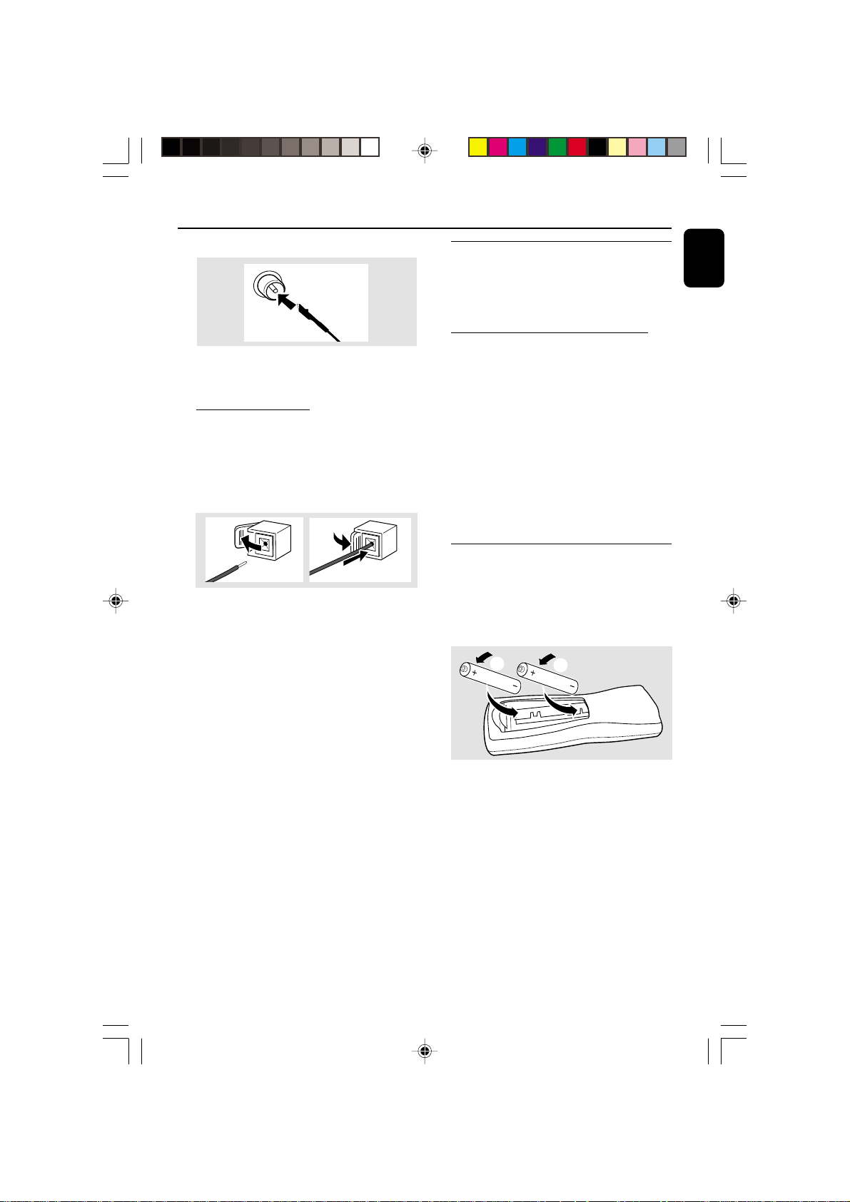
Inserting batteries into the
remote control
Insert two batteries (Type R06 or AA) into the
remote control with the correct polarity as
indicated by the "+" and "-" symbols inside
the battery compar tment.
English
pg 001-030/C399/22-Eng 1/29/02, 5:55 PM9
CAUTION!
– Remove batteries if they are exhausted
or will not be used for a long time.
– Do not use old and new or different
types of batteries in combination.
– Batteries contain chemical substances, so
they should be disposed off properly.
9
3139 115 21221
 Loading...