


TEMPERATURE CONTROLLER
KT9
INSTRUCTION MANUAL
CTi Automation - Phone: 800.894.0412 - Fax: 208.368.0415 - Web: www.ctiautomation.net - Email: info@ctiautomation.net

Preface
Thank you for the purchase of  Temperature controller KT9.
This manual contains instructions for the mounting, functions, operations and notes when operating the KT9.
For model confirmation and unit specifications, please read this manual carefully before starting operation.
To prevent accidents arising from the misuse of this controller, please ensure the operator receives this manual.
Notes
•This instrument should be used according to the specifications described in the manual. If it is not used according to the specifications, it may malfunction or cause fire.
•Be sure to follow the warnings, cautions and notices. If they are not observed, it could cause serious injury or accidents.
•The contents of this instruction manual are subject to change without notice.
•Care has been taken to assure that the contents of this instruction manual are correct, but if there are any doubts, mistakes or questions, please inform our sales department.
•This instrument is designed to be installed in a control panel. If it is not, measures must be taken to ensure that the operator cannot touch power terminals or other high voltage sections.
•Any unauthorized transfer or copying of this document, in part or in whole, is prohibited.
•Matsushita Electric Works, Ltd. is not responsible for any damage or secondary damage(s) incurred as a result of using this product, including any indirect damage.
•To pull out the inner assembly, release the hooks at the top and bottom of the instrument with thin, hard tweezers. (If the hooks are released too far, they may be broken, or IP66 function could deteriorate. Do not pull out the inner assembly except when repairing the instrument.)
SAFETY PRECAUTIONS
(Be sure to read these precautions before using our products.)
The safety precautions are classified into categories: “Warning” and “Caution”.
Depending on circumstances, procedures indicated by  Caution may be linked to serious results, so be sure to follow the directions for usage.
 Warning
Procedures which may lead to dangerous conditions and cause death or serious injury, if not carried out properly.
 Caution
Procedures which may lead to dangerous conditions and cause superficial to medium injury or physical damage or may degrade or damage the product, if not carried out properly.
2
CTi Automation - Phone: 800.894.0412 - Fax: 208.368.0415 - Web: www.ctiautomation.net - Email: info@ctiautomation.net

1. Installation precautions
 Caution
This instrument is intended to be used under the following environmental conditions (IEC61010-1): Overvoltage category  , Pollution degree 2
Ensure the mounting location corresponds to the following conditions:
•A minimum of dust, and an absence of corrosive gases
•No flammable, explosive gases
•No mechanical vibrations or shocks
•No exposure to direct sunlight, an ambient temperature of 0 to 50 (32 to 122
 ) that does not change rapidly
•An ambient non-condensing humidity of 35 to 85%RH
•No large capacity electromagnetic switches or cables through which large current is flowing
•No water, oil or chemicals or where the vapors of these substances can come into
direct contact with the unit
Note: Do not install this instrument near flammable material even though the case of this instrument is made of flame-resistant resin.
Avoid setting this instrument directly on flammable material.
2. Wiring precautions
 Caution
•Use the solderless terminal with an insulation sleeve that fits in the M3 screw when wiring the KT9 Series.
•The terminal block of this instrument is designed to be wired from the left side. The lead wire must be inserted from the left side of the terminal, and fastened with the terminal screw.
•Tighten the terminal screw within the specified torque.
If excessive force is applied to the screw when tightening, the terminal screw or case may be damaged.
•Do not apply a commercial power source to the sensor which is connected to the input terminal nor allow the power source to come into contact with the sensor.
•This controller does not have built-in power switch, circuit breaker or fuse. It is necessary to install them near the controller.
(Recommended fuse: Time-lag fuse, rated voltage 250V AC, rated current 2A)
•For a 24V AC/DC power source, do not confuse polarity when using direct current (DC).
3. Running and maintenance precautions
 Warning
•It is recommended that the PID auto-tuning be performed on the trial run.
•Do not touch live terminals. This may cause electric shock or problems in operation.
•Turn the power supply to the instrument OFF before retightening the terminal and cleaning.
Working or touching the terminal with the power switched ON may result in severe
injury or death due to Electric Shock.
•Use a soft, dry cloth when cleaning the instrument. (Alcohol based substances may tarnish or deface the unit)
•As the display section is vulnerable, do not strike or scratch it with a hard object.
3
CTi Automation - Phone: 800.894.0412 - Fax: 208.368.0415 - Web: www.ctiautomation.net - Email: info@ctiautomation.net
--- CONTENTS ---
1. Model number
1.1 |
Explanation of model number ---------------------------------------------------- |
6 |
1.2 |
Rated input ---------------------------------------------------------------------------- |
7 |
1.3 |
How to read the rated label ------------------------------------------------------- |
7 |
2. Name and functions of the sections ------------------------------------ |
8 |
|
3. Mounting to the control panel |
|
|
3.1 |
Site selection ----------------------------------------------------------------------- |
10 |
3.2 |
External dimensions (Unit: mm) ----------------------------------------------- |
10 |
3.3 |
Panel cutout (Unit: mm) ---------------------------------------------------------- |
10 |
3.4 |
CT (current transformer) external dimensions (Unit: mm) --------------- |
11 |
3.5 |
Mounting ----------------------------------------------------------------------------- |
11 |
4. Wiring |
|
|
4.1 Terminal arrangement ------------------------------------------------------------ |
12 |
|
4.2 |
Wiring examples ------------------------------------------------------------------- |
13 |
5. Setup |
|
|
5.1 |
Operation flowchart --------------------------------------------------------------- |
16 |
5.2 |
Main setting mode |
|
SV1 ------------------------------------------------------------------------------------- |
18 |
|
SV2 ------------------------------------------------------------------------------------- |
18 |
|
5.3 |
Output MV indication -------------------------------------------------------------- |
18 |
5.4 |
Sub setting mode |
|
AT/Auto-reset ------------------------------------------------------------------------ |
18 |
|
OUT1 proportional band ---------------------------------------------------------- |
19 |
|
OUT2 proportional band ---------------------------------------------------------- |
19 |
|
Integral time -------------------------------------------------------------------------- |
19 |
|
Derivative time ---------------------------------------------------------------------- |
19 |
|
ARW (Anti-reset windup) --------------------------------------------------------- |
19 |
|
OUT1 proportional cycle ---------------------------------------------------------- |
19 |
|
OUT2 proportional cycle --------------------------------------------------------- |
19 |
|
A1 value ------------------------------------------------------------------------------ |
20 |
|
A2 value ------------------------------------------------------------------------------ |
20 |
|
HB (Heater burnout alarm) value ---------------------------------------------- |
20 |
|
5.5 Auxiliary function setting mode 1 |
|
|
Set value lock ----------------------------------------------------------------------- |
21 |
|
SV high limit ------------------------------------------------------------------------- |
21 |
|
SV low limit -------------------------------------------------------------------------- |
21 |
|
Sensor correction ------------------------------------------------------------------ |
21 |
|
Communication protocol --------------------------------------------------------- |
21 |
|
Instrument number ---------------------------------------------------------------- |
21 |
|
Communication speed ------------------------------------------------------------ |
21 |
|
Parity ---------------------------------------------------------------------------------- |
22 |
|
Stop bit -------------------------------------------------------------------------------- |
22 |
|
5.6 Auxiliary function setting mode 2 |
|
|
Input type ----------------------------------------------------------------------------- |
22 |
|
Scaling high limit ------------------------------------------------------------------- |
23 |
|
Scaling low limit -------------------------------------------------------------------- |
23 |
|
Decimal point place --------------------------------------------------------------- |
23 |
|
PV filter time constant ------------------------------------------------------------ |
23 |
|
|
4 |
|
CTi Automation - Phone: 800.894.0412 - Fax: 208.368.0415 - Web: www.ctiautomation.net - Email: info@ctiautomation.net
--- CONTENTS ---
OUT1 high limit ---------------------------------------------------------------------- |
23 |
|
OUT1 low limit ----------------------------------------------------------------------- |
23 |
|
OUT1 ON/OFF action hysteresis ----------------------------------------------- |
23 |
|
OUT2 action mode ----------------------------------------------------------------- |
23 |
|
OUT2 high limit ---------------------------------------------------------------------- |
24 |
|
OUT2 low limit ----------------------------------------------------------------------- |
24 |
|
Overlap band/Dead band --------------------------------------------------------- |
24 |
|
OUT2 ON/OFF action hysteresis ----------------------------------------------- |
24 |
|
A1 type -------------------------------------------------------------------------------- |
24 |
|
A2 type -------------------------------------------------------------------------------- |
25 |
|
A1 action Energized/Deenergized --------------------------------------------- |
25 |
|
A2 action Energized/Deenergized --------------------------------------------- |
25 |
|
A1 hysteresis ------------------------------------------------------------------------ |
25 |
|
A2 hysteresis ------------------------------------------------------------------------ |
25 |
|
A1 action delayed timer ----------------------------------------------------------- |
25 |
|
A2 action delayed timer ----------------------------------------------------------- |
25 |
|
Direct/Reverse action ------------------------------------------------------------- |
26 |
|
AT bias -------------------------------------------------------------------------------- |
26 |
|
Setting item not used -------------------------------------------------------------- |
26 |
|
SV2 indication ---------------------------------------------------------------------- |
26 |
|
Output status selection when input abnormal ------------------------------- |
26 |
|
OUT/OFF key function ------------------------------------------------------------ |
26 |
|
5.7 |
Control output OFF function --------------------------------------------------- |
27 |
5.8 Auto/Manual control -------------------------------------------------------------- |
27 |
|
6. Running ----------------------------------------------------------------------------- |
28 |
|
7. Action explanation |
|
|
7.1 |
OUT1 action ------------------------------------------------------------------------ |
29 |
7.2 |
Heater burnout alarm action (option) ----------------------------------------- |
29 |
7.3 |
OUT1 ON/OFF action ------------------------------------------------------------ |
30 |
7.4 |
OUT2 (Heating/Cooling control) action (option) --------------------------- |
31 |
7.5 |
OUT2 (Heating/Cooling control) action (when setting Dead band) --- |
32 |
7.6 |
OUT2 (Heating/Cooling control) action (when setting Overlap band) -33 |
|
7.7 A1, A2 action ------------------------------------------------------------------------ |
34 |
|
7.8 |
SV1/SV2 external selection ----------------------------------------------------- |
35 |
8. Control action explanations |
|
|
8.1 |
PID ------------------------------------------------------------------------------------ |
35 |
8.2 |
PID auto-tuning of this controller ---------------------------------------------- |
35 |
8.3 Auto-reset (offset correction) --------------------------------------------------- |
36 |
|
9. Specifications |
|
|
9.1 |
Standard specifications ---------------------------------------------------------- |
37 |
9.2 |
Optional specifications ----------------------------------------------------------- |
42 |
10.Troubleshooting |
|
|
10.1 Indication -------------------------------------------------------------------------- |
44 |
|
10.2 Key operation -------------------------------------------------------------------- |
45 |
|
10.3 Control ----------------------------------------------------------------------------- |
46 |
|
11. Character table ----------------------------------------------------------------- |
46 |
|
|
5 |
|
CTi Automation - Phone: 800.894.0412 - Fax: 208.368.0415 - Web: www.ctiautomation.net - Email: info@ctiautomation.net
1.Model number
1.1Explanation of model number
|
A K T 9 |
1 |
|
|
|
|
|
|
|
|
|
|
|
||
|
|
|
|
|
|
|
|
|
|
|
|
||||
|
|
|
|
|
|
|
|
|
|
|
|
|
|
|
|
|
(1) |
(2) |
(3) |
(4) |
(5) |
(6) |
(7) |
|
|||||||
(1) |
Supply voltage ---------------------- |
|
|
|
|
1: 100 to 240V AC 2: 24V AC/DC |
|||||||||
(2) |
Input type ----------------------------- |
|
|
|
|
1: Multi-input (Thermocouple, RTD, DC current |
|||||||||
|
|
|
|
|
|
|
|
|
|
|
|
|
|
and DC voltage can be selected |
|
|
|
|
|
|
|
|
|
|
|
|
|
|
|
by keypad operation) |
|
(3) |
Control output (OUT1) |
|
|
1: Relay contact |
2: Non-contact voltage |
||||||||||
|
|
|
|
|
|
|
3: DC current |
|
|||||||
(4) Alarm output ------------------------- |
|
|
|
|
1: A1 output 2: A1 output + A2 output |
||||||||||
|
|
|
|
|
|
|
(The alarm type and Energized /Deenergized |
||||||||
|
|
|
|
|
|
|
can be selected by keypad operation) |
||||||||
(5) |
Heating/Cooling control (OUT2) output: |
|
|
|
|
|
|||||||||
|
|
|
|
|
|
|
0: Not available |
1: Relay contact |
|||||||
|
|
|
|
|
|
|
2: Non-contact voltage 3: DC current |
||||||||
(6) |
Heater burnout alarm ------------- |
|
|
0: Not available |
1: Available (5A) 2: Available |
||||||||||
|
|
|
|
|
|
|
(10A) |
3: Available (20A) 4: Available (50A) |
|||||||
|
|
|
|
|
|
|
(Heater burnout alarm is not available for the DC |
||||||||
|
|
|
|
|
|
|
current output) |
|
|||||||
(7) Serial communication ------------- |
|
|
1: Applied (The number is added only when Serial |
||||||||||||
|
|
|
|
|
|
|
|
|
|
|
|
|
|
communication is applied.) |
|
6
CTi Automation - Phone: 800.894.0412 - Fax: 208.368.0415 - Web: www.ctiautomation.net - Email: info@ctiautomation.net

1.2 Rated input
Input type |
|
Input range |
|
Resolution |
||||
|
|
|
|
|
|
|
|
|
|
K |
–200 to 1370 |
|
–320 to 2500 |
1 |
( |
) |
|
|
–199.9 to 400.0 |
|
–199.9 to 750.0 |
0.1 |
( |
) |
||
|
|
|
||||||
|
J |
–200 to 1000 |
|
–320 to 1800 |
1 |
( |
) |
|
|
R |
0 to 1760 |
|
|
0 to 3200 |
1 |
( |
) |
|
S |
0 to 1760 |
|
|
0 to 3200 |
1 |
( |
) |
|
B |
0 to 1820 |
|
|
0 to 3300 |
1 |
( |
) |
|
E |
–200 to 800 |
|
–320 to 1500 |
1 |
( |
) |
|
|
T |
–199.9 to 400.0 |
|
–199.9 to 750.0 |
0.1 |
( |
) |
|
|
N |
–200 to 1300 |
|
–320 to 2300 |
1 |
( |
) |
|
|
PL- |
0 to 1390 |
|
|
0 to 2500 |
1 |
( |
) |
C(W/Re5-26) |
0 to 2315 |
|
|
0 to 4200 |
1 |
( |
) |
|
Pt100 |
–199.9 to 850.0 |
|
–199.9 to 999.9 |
0.1 |
( |
) |
||
–200 to 850 |
|
–300 to 1500 |
1 |
( |
) |
|||
|
|
|
||||||
JPt100 |
–199.9 to 500.0 |
|
–199.9 to 900.0 |
0.1 |
( |
) |
||
–200 to 500 |
|
–300 to 900 |
1 |
( |
) |
|||
|
|
|
||||||
4 to 20mA DC |
|
–1999 |
to 9999 |
*1, *2 |
1 |
|
|
|
0 to 20mA DC |
|
–1999 to 9999 |
*1, *2 |
1 |
|
|
||
0 to |
1V DC |
|
–1999 to 9999 |
*1 |
1 |
|
|
|
0 to 10V DC |
|
–1999 to 9999 |
*1 |
1 |
|
|
||
1 to |
5V DC |
|
–1999 to 9999 |
*1 |
1 |
|
|
|
0 to |
5V DC |
|
–1999 to 9999 |
*1 |
1 |
|
|
|
*1: For DC input, the input range and decimal point place can be changed.
*2: 50 shunt resistor (AKT4810, sold separately) must be connected between input terminals
1.3How to read the rated label
The rated label is attached to the case.
(1)A K T 9 1 1 1 1 0 0 1
(2)No.
(e.g.)
Supply voltage: 100 to 240V AC Multi-input
Relay contact output A1 output
Heating/Cooling control is not added. Heater burnout alarm is not added. Serial communication is added.
(1)Model number, supply voltage, input type, output type, etc. are entered.
(2)Lot number is entered.
7
CTi Automation - Phone: 800.894.0412 - Fax: 208.368.0415 - Web: www.ctiautomation.net - Email: info@ctiautomation.net
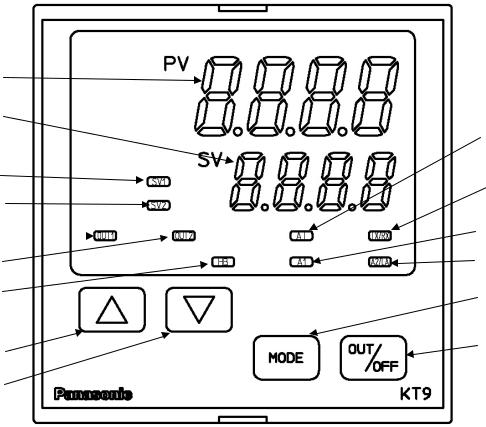
2. Name and functions of the sections
(1) |
|
|
|
(2) |
(8) |
||
|
|||
(3) |
(9) |
||
(4) |
|||
|
|
||
(5) |
|
(10) |
|
(11) |
|||
(6) |
|||
(7) |
(14) |
||
(12) |
(15) |
||
|
|
||
(13) |
|
|
|
(Fig. 2-1)
(1) PV display
Indicates the PV (process variable) with a red LED.
(2) SV display
Indicates the SV (main set value) or MV (manipulated variable) with a green LED.
(3) SV1 indicator
The green LED lights when SV1 is selected.
(4) SV2 indicator
The green LED lights when SV2 is selected.
(5) OUT1 indicator
When OUT1 or Heating output is on, the green LED lights.
(For the DC current output type, this flashes corresponding to the output manipulated variable in 0.25 second cycles)
(6) OUT2 indicator
When OUT2 is on, the yellow LED lights.
(For the DC current output type, this flashes corresponding to the output manipulated variable in 0.25 second cycles)
(7) HB indicator
When Heater burnout alarm output or sensor burnout alarm output is on, the red LED lights. (When Heater burnout alarm is added and if indication is overscale or underscale, the red LED lights as well)
8
CTi Automation - Phone: 800.894.0412 - Fax: 208.368.0415 - Web: www.ctiautomation.net - Email: info@ctiautomation.net

(8) AT indicator
The yellow LED flashes during auto-tuning or auto-reset.
(9) TX/RX indicator
The yellow LED flashes during Serial communication. (10) A1 indicator
When A1 output is on, the red LED lights. (11) A2/LA indicator
When A2 output is on, the red LED lights.
(12)Increase key: Increases the numeric value.
(13)Decrease key: Decreases the numeric value.
(14)Mode key: Selects the setting mode or registers the set value.
(By pressing the Mode key, the set value or selected value can be registered.)
(15)OUT/OFF key
•If OUT/OFF function is selected during OUT/OFF function selection, the control output is turned on or off.
Once the control output OFF function is enabled, the function cannot be released even if the power to the instrument is turned OFF and turned ON again.
To cancel the function, press the OUT/OFF key again for approx. 1 second.
•If Auto/Manual control function is selected from OUT/OFF function selection, automatic control is performed when the power to the controller is turned on. In this status, if the OUT/OFF key is pressed, the automatic control output is switched to manual control output and vice versa. However, this function can be switched only in the PV/SV display mode.
 Notice
When setting the specifications and functions of this controller, connect terminals 2 and 3 for power source first, then set them referring to “5. Setup” before performing “3. Mounting to the control panel” and “4. Wiring”.
9
CTi Automation - Phone: 800.894.0412 - Fax: 208.368.0415 - Web: www.ctiautomation.net - Email: info@ctiautomation.net

3.Mounting to the control panel
3.1Site selection
This instrument is intended to be used under the following environmental conditions (IEC61010-1): Overvoltage category  , Pollution degree 2
Ensure the mounting location corresponds to the following conditions:
(1)A minimum of dust, and an absence of corrosive gases
(2)No flammable, explosive gases
(3)No mechanical vibrations or shocks
(4)No exposure to direct sunlight, an ambient temperature of 0 to 50 (32 to 122
 ) that does not change rapidly
(5)An ambient non-condensing humidity of 35 to 85%RH
(6)No large capacity electromagnetic switches or cables through which large current is flowing
(7)No water, oil or chemicals or where the vapors of these substances can come into direct contact with the unit
3.2External dimensions (Unit: mm)
Gasket Screw type mounting bracket Terminal cover
96 |
91 106.2 |
11.5 |
98.5 |
96 |
104.5 (*) |
(Fig. 3.2-1)
3.3 Panel cutout (Unit: mm)
130
(*): When terminal cover is used
0.8 □92 0
n×96-3 00.5
|
|
Lateral close mounting |
|
|
n: Number of units mounted |
□92 00.8 |
Caution: If lateral close mounting is used for the controller, |
|
|
IP66 specification may be compromised, and all |
|
|
|
warranties will be invalidated. |
|
(Fig. |
3.3-1) |
|
|
10 |
CTi Automation - Phone: 800.894.0412 - Fax: 208.368.0415 - Web: www.ctiautomation.net - Email: info@ctiautomation.net
3.4 CT (Current transformer) external dimensions (Unit: mm)
AKT4815 (for 5A, 10A and 20A) |
AKT4816 (for 50A) |
(Fig. |
3.4-1) |
3.5 Mounting
 Notice
As the case is made of resin, do not use excessive force while screwing in the mounting bracket, or the case or screw type mounting bracket could be damaged. The torque is approximately 0.12N•m.
Mount the controller vertically to the flat, rigid panel to ensure it adheres to the Dust-proof/Drip-proof specification (IP66).
Mounting panel thickness: 1 to 15mm.
Insert the instrument from the front side of the panel.
Attach the mounting bracket by the holes at the top and bottom of the case and secure in place with the screws.
(Fig. 3.5-1)
11
CTi Automation - Phone: 800.894.0412 - Fax: 208.368.0415 - Web: www.ctiautomation.net - Email: info@ctiautomation.net
4. Wiring
 Warning
Turn the power supply to the instrument off before wiring or checking. Working or touching the terminal with the power switched on may result in severe injury or death due to Electric Shock.
Moreover, the instrument must be grounded before the power supply to the instrument is turned on.
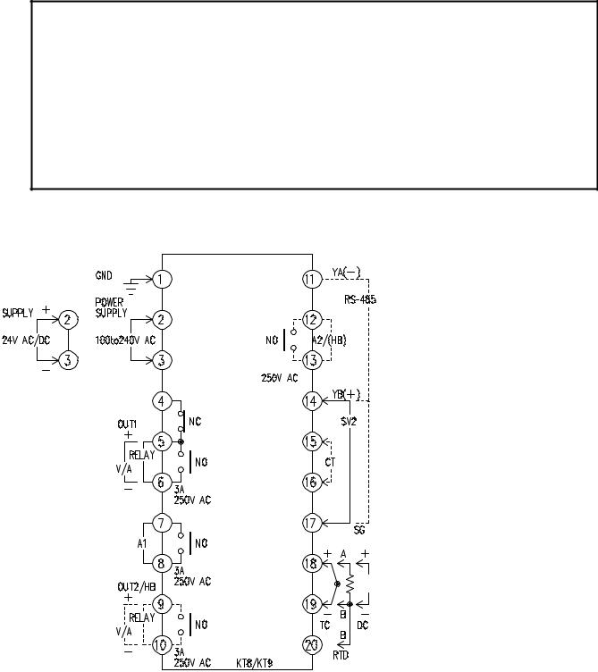
4.1 Terminal arrangement
• OUT1 |
: Control output 1 |
|
(Heating output) |
• OUT2 |
: Control output 2 |
|
(Cooling output) |
• RELAY : Relay contact output |
|
• V/A |
: Non-contact voltage |
|
output/DC current output |
• A1 |
: Alarm 1 output |
• A2 |
: Alarm 2 output |
• HB |
: Heater burnout alarm |
|
output |
• RS-485: Serial communication
• SV2 |
: 2nd SV |
• CT |
: CT input |
• TC |
: Thermocouple |
• RTD |
: Resistance |
|
temperature detector |
• DC |
: DC current or |
|
DC voltage |
(Fig. 4.1-1)
12
CTi Automation - Phone: 800.894.0412 - Fax: 208.368.0415 - Web: www.ctiautomation.net - Email: info@ctiautomation.net
 Notice
•The terminal block of KT9 series is designed to be wired from the left side. The lead wire must be inserted from the left side of the terminal, and fastened with the terminal screw.
•Dotted lines show options.
•If A2 (option) and Heater burnout alarm (option) are applied together, use terminals 12-13 for A2, and 9-10 for the Heater burnout alarm.
•If the Heating/Cooling control (option) and Heater burnout alarm (option) are applied together, use terminals 9-10 for the Heating/Cooling control, and 12-13 for the Heater burnout alarm.
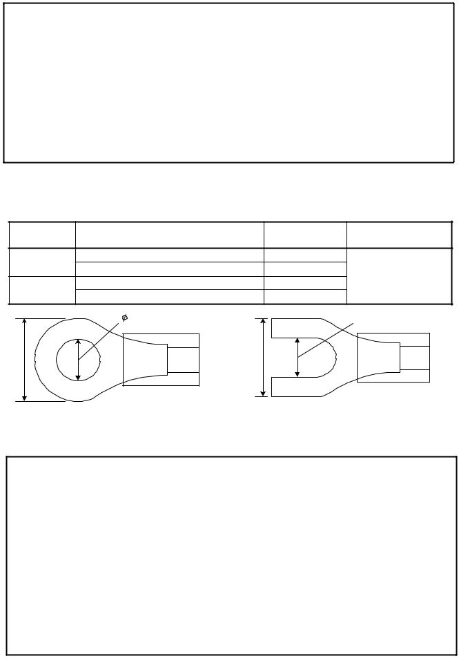
 Lead wire solderless terminal
Use a solderless terminal with an insulation sleeve in which an M3 screw fits as shown below.
Solderless |
Manufacturer |
Model |
Tightening torque |
|
terminal |
||||
|
|
|
||
Y type |
Nichifu Terminal Industries CO.,LTD. |
1.25Y-3 |
|
|
Japan Solderless Terminal MFG CO.,LTD. |
VD1.25-B3A |
0.6N•m |
||
|
||||
Round type |
Nichifu Terminal Industries CO.,LTD. |
1.25-3 |
Max. 1.0N•m |
|
Japan Solderless Terminal MFG CO.,LTD. V1.25-3 |
|
|||
|
|
|||
|
3.2mm |
|
3.2mm |
|
5.8mm or less |
5.8mm or less |
|
|
|
(Fig. 4.1-2)
4.2 Wiring examples
 Notice
•Use a thermocouple and compensating lead wire according to the sensor input specifications of this controller.
•Use the 3-wire RTD according to the sensor input specifications of this controller.
•This controller does not have built-in power switch, circuit breaker or fuse. It is necessary to install them in the circuit near the external controller.
(Recommended fuse: Time-lag fuse, rated voltage 250V AC, rated current 2A)
•For a 24V AC/DC power source, do not confuse polarity when using direct current (DC).
•When using a relay contact output type, use a relay externally according to the capacity of the load to protect the built-in relay contact.
•When wiring, keep the input wire (Thermocouple, RTD, etc.) away from AC sources or load wires to avoid external interference.
•Use a thick wire (1.25 to 2.0mm2) for grounding.
13
CTi Automation - Phone: 800.894.0412 - Fax: 208.368.0415 - Web: www.ctiautomation.net - Email: info@ctiautomation.net

[Heater burnout alarm output]
(1)This alarm is not available for detecting heater current under phase control.
(2)This alarm is not available for detecting 3-phase heater current.
(3)Use the current transformer (CT) provided, and pass one lead wire of the heater circuit into the hole of the CT.
(4)When wiring, keep CT wire away from any AC source and load wire to avoid external interference.
[AKT9111100]
3-phase
100 to 240V AC or 24V AC/DC
Electromagnetic switch
1516 CT input terminals
Power source
CT
Heater
(Fig. 4.2-1)
|
Alarm unit |
Heater |
Thermocouple |
Electric furnace |
|
|
(Fig. 4.2-2) |
* To prevent the unit from harmful effects of unexpected high level noise, it is recommended that a surge absorber be installed between the electromagnetic switch coils.
• For a 24V AC/DC power source, do not confuse polarity when using direct current (DC). 14
CTi Automation - Phone: 800.894.0412 - Fax: 208.368.0415 - Web: www.ctiautomation.net - Email: info@ctiautomation.net
5. Setup
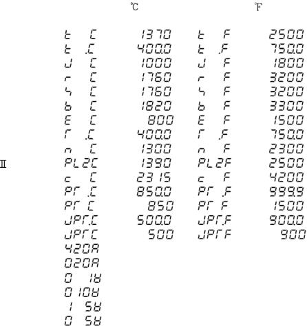
For the thermocouple and RTD input, the sensor input characters and temperature unit are indicated on the PV display and the input range high limit value is indicated on the SV display for approx. 3 seconds after the power is turned on. See (Table 5-1).
For DC input, the sensor input characters are indicated on the PV display and the scaling high limit value is indicated on the SV display. See (Table 5-1).
If any other value is set during the scaling high limit setting, the set value is indicated on the SV display.
During this time, all outputs and the LED indicators are in OFF status.
Control will then start and the PV (process variable) will be indicated on the PV display and SV1 or SV2 will be indicated on the SV display.
While control output OFF function is working, 
 is indicated on the PV display. To release the function, press the OUT/OFF key for approx. 1 second.
(Table 5-1)
Sensor input |
|
|
|
|
||
PV display |
SV display |
PV display |
SV display |
|||
|
|
|||||
|
|
|
|
|
|
|
|
K |
|
|
|
|
|
|
|
|
|
|
||
|
|
|
|
|
|
|
|
J |
|
|
|
|
|
|
R |
|
|
|
|
|
|
S |
|
|
|
|
|
|
B |
|
|
|
|
|
|
E |
|
|
|
|
|
|
T |
|
|
|
|
|
|
N |
|
|
|
|
|
PL- |
|
|
|
|
||
C (W/Re5-26) |
|
|
|
|
||
Pt100 |
|
|
|
|
||
|
|
|
|
|||
|
|
|
|
|
||
JPt100 |
|
|
|
|
||
|
|
|
|
|||
|
|
|
|
|
||
4 to 20mA DC |
|
|
|
|
||
0 to 20mA DC |
|
|
|
|
||
0 to |
1V DC |
|
Scaling high limit value |
|||
0 to 10V DC |
|
|||||
|
|
|
|
|||
1 to |
5V DC |
|
|
|
|
|
0 to |
5V DC |
|
|
|
|
|
15
CTi Automation - Phone: 800.894.0412 - Fax: 208.368.0415 - Web: www.ctiautomation.net - Email: info@ctiautomation.net
 Loading...