


TEMPERATURE CONTROLLER
KT2
INSTRUCTION MANUAL

Preface
Thank you for purchasing  Temperature Controller KT2.
This manual contains instructions for the mounting, functions, operations and notes for operating the KT2. For model confirmation and unit specifications, please read this manual carefully before starting operation.
To prevent accidents arising from the misuse of this controller, please ensure the operator receives this manual.
Characters used in this manual
Indication |
|
|
|
|
|
|
|
|
|
|
|
|
|
Number, / |
-1 |
0 |
1 |
2 |
3 |
4 |
5 |
6 |
7 |
8 |
9 |
|
|
Indication |
|
|
|
|
|
|
|
|
|
|
|
|
|
Alphabet |
A |
B |
C |
D |
E |
F |
G |
H |
I |
J |
K |
L |
M |
Indication |
|
|
|
|
|
|
|
|
|
|
|
|
|
Alphabet |
N |
O |
P |
Q |
R |
S |
T |
U |
V |
W |
X |
Y |
Z |
Notes
•This instrument should be used in accordance with the specifications described in the manual. If it is not used in accordance with the specifications, it may malfunction or cause fire.
•Be sure to follow the warnings, cautions and notices. If warnings are not observed, serious injury or accidents may occur.
•The contents of this instruction manual are subject to change without notice.
•Care has been taken to assure that the contents of this instruction manual are correct, but if there are any doubts, mistakes or questions, please inform our sales department.
•This instrument is designed to be installed in a control panel. If it is not, measures must be taken to ensure that power terminals or other high voltage sections cannot be touched.
•Any unauthorized transfer or copying of this document, in part or in whole, is prohibited.
•Panasonic Electric Works Co., Ltd. is not liable for any damage or secondary damage(s) incurred as a result of using this product, including any indirect damage.
Safety precautions
(Be sure to read these precautions before using our products.)
The safety precautions are classified into two categories: “Warning” and “Caution”.
Depending on circumstances, procedures indicated by  Caution may have serious consequences, so be sure to follow the directions for correct usage.
 Warning
Procedures which may lead to dangerous conditions and cause death or serious injury, if not carried out properly.
 Caution
Procedures which may lead to dangerous conditions and cause superficial to medium injury or physical damage or may degrade or damage the product, if not carried out properly.
2

1. Installation precautions
Caution
This instrument is intended to be used under the following environmental conditions (IEC61010-1): Overvoltage category  , Pollution degree 2
Ensure the mounting location corresponds to the following conditions:
•A minimum of dust, and an absence of corrosive gases
•No flammable or explosive gases
•No mechanical vibrations or shocks
•No exposure to direct sunlight, an ambient temperature of 0 to 50 (32 to 122
 ) that does not change rapidly
•An ambient non-condensing humidity of 35 to 85%RH
•No large capacity electromagnetic switches or cables through which large current is flowing
•No water, oil or chemicals or where the vapors of these substances can come into contact with the unit
Note: Do not install this instrument near flammable material even though the case of this instrument is made of flame-resistant resin.
Avoid setting this instrument directly on flammable material.
2. Wiring precautions
Caution
•Use the solderless terminal with an insulation sleeve in which an M3 screw fits, when wiring the KT2.
•Tighten the terminal screw with the specified torque. If excessive force is applied to the screw when tightening, the terminal screw or case may be damaged.
•Do not apply a commercial power source to the sensor which is connected to the input terminal nor allow the power source to come into contact with the sensor.
•This controller does not have built-in power switch, circuit breaker or fuse. It is necessary to install them near the controller.
(Recommended fuse: Time-lag fuse, rated voltage 250V AC, rated current 2A)
3. Running and maintenance precautions
Warning
•It is recommended that the PID auto-tuning be performed on the trial run.
•Do not touch live terminals. This may cause electric shock or problems in operation.
•Turn the power supply to the instrument OFF before retightening the terminal and cleaning.
Working or touching the terminal with the power switched ON may result in severe injury or death due to Electric Shock.
•Use a soft, dry cloth when cleaning the instrument. (Alcohol based substances may tarnish or deface the unit)
•As the display section is vulnerable, do not strike or scratch it with a hard object.
3
|
--- CONTENTS --- |
|
1. Model number |
|
|
1.1 |
Model number ----------------------------------------------------------------------- |
5 |
1.2 |
How to read the rated label ------------------------------------------------------ |
5 |
2. Name and functions of the sections ------------------------------------- |
5 |
|
3. Mounting to the control panel |
|
|
3.1 |
Site selection ------------------------------------------------------------------------- |
6 |
3.2 |
External dimensions ---------------------------------------------------------------- |
6 |
3.3 |
Panel cutout -------------------------------------------------------------------------- |
6 |
3.4 |
Mounting ------------------------------------------------------------------------------ |
6 |
4. Wiring ------------------------------------------------------------------------------------- |
7 |
|
5. Setup procedures |
|
|
5.1 |
Setup procedures ------------------------------------------------------------------ |
8 |
5.2 |
Initial setting ------------------------------------------------------------------------- |
8 |
6. Setup |
|
|
6.1 |
Main setting mode ----------------------------------------------------------------- |
14 |
6.2 |
Sub setting mode ------------------------------------------------------------------ |
16 |
6.3 Auxiliary function setting mode 1 ---------------------------------------------- |
17 |
|
7. Running |
|
|
7.1 |
Start running ------------------------------------------------------------------------ |
18 |
7.2 |
MV (Control output manipulated variable) indication --------------------- |
19 |
7.3 |
Control output OFF function ---------------------------------------------------- |
19 |
7.4 Auto-tuning (AT) Perform/Cancel ---------------------------------------------- |
19 |
|
8. Operation flowchart -------------------------------------------------------------- |
20 |
|
9. PID auto-tuning -------------------------------------------------------------------- |
22 |
|
10. Action explanation |
|
|
10.1 OUT1 (Heating) action --------------------------------------------------------- |
23 |
|
10.2 OUT1 (Heating) ON/OFF action --------------------------------------------- |
23 |
|
10.3 A1, A2 action --------------------------------------------------------------------- |
24 |
|
10.4 Heating/Cooling control action (Heating/Cooling control option) --- |
24 |
|
10.5 Heating/Cooling control action (When setting dead band) |
|
|
|
(Heating/Cooling control option) --------------------------------------------- |
25 |
10.6 Heating/Cooling control action (When setting overlap band) |
|
|
|
(Heating/Cooling control option) --------------------------------------------- |
25 |
10.7 Timer action ----------------------------------------------------------------------- |
25 |
|
11. Specifications |
|
|
11.1 Standard specifications --------------------------------------------------------- |
26 |
|
11.2 Optional specifications ---------------------------------------------------------- |
28 |
|
12.Troubleshooting |
|
|
12.1 Indication --------------------------------------------------------------------------- |
29 |
|
12.2 Key operation --------------------------------------------------------------------- |
30 |
|
12.3 Control ------------------------------------------------------------------------------ |
30 |
|
13. Character table ------------------------------------------------------------------- |
31 |
|
4
1.Model number
1.1Model number
|
A K T 2 |
1 |
|
|
|
0 |
|
|
|
(1) |
(2) |
(3) |
(4) |
(5) |
(6) |
|
|
(1) |
Supply voltage ---------------------- |
|
|
|
1: 100 to 240V AC |
2: 24V AC/DC |
||
(2) |
Input type ----------------------------- |
|
|
|
1: Multi-input (Thermocouple, RTD, DC current and DC voltage |
|||
|
|
|
|
|
|
can be selected by keypad) |
||
(3) |
Control output (OUT1) |
----------- |
|
1: Relay contact |
2: Non-contact voltage 3: DC current |
|||
(4) Alarm output ------------------------- |
|
|
|
0: Not available (When both Healing/Cooling control and Serial |
||||
|
|
|
|
|
|
communication are selected) |
||
|
|
|
|
|
1: A1 output or A2 output (However, if Healing/Cooling control |
|||
|
|
|
|
|
|
is selected, only A2 output is available. If Serial communication |
||
|
|
|
|
|
|
is selected, only A1 output is available) |
||
|
|
|
|
|
2: A1 output + A2 output (When neither Healing/Cooling control |
|||
|
|
|
|
|
nor Serial communication is selected) |
|||
(5) |
Heating/Cooling control (OUT2) output: 0: Not available |
1: Relay contact |
||||||
(6) Serial communication ------------- |
Blank: Not available |
1: Applied |
||||||
1.2 How to read the rated label
The rated label is attached to the case and the inner assembly. (For case) (For inner assembly)
 1
1 
2  (Fig. 1.2-2)
1: Model number, supply voltage, input type, output type, etc. are entered
(Fig. 1.2-1) |
2 : Lot number is entered. |
(Example)
Supply voltage: 100 to 240V AC Multi-input
Relay contact output A1 output + A2 output
Heating/Cooling control is not added Serial communication is not added
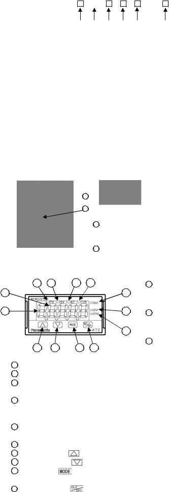
2. Name and functions of the sections
3 |
4 |
5 |
6 |
1 |
|
|
7 |
2 |
|
|
8 |
|
|
|
9 |
10 |
11 |
12 |
13 |
(Fig. 2-1)
1PV/SV display (red): Indicates the PV (Process variable) and SV (Main set value). During setting mode, characters and set value of each setting item are indicated alternately.
2MEMO/STEP display (green): Indicates memory number during fixed value control. Indicates step number during program control.
3PV indicator (red): Lights when the PV (Process variable)
is indicated.
4SV indicator (green) : Lights when SV (main set value) is indicated.
5AT indicator (yellow) : Flashes during AT (auto-tuning).
6T/R indicator (yellow): Flashes during Serial communication.
|
|
|
(Lit while sending data, Unlit while receiving data) |
7 |
OUT indicator (green): Lights when control output or OUT1 (Heating side, Heating/Cooling control |
||
|
|
|
option) is ON. (For DC current output type, it flashes corresponding to the |
|
EV1 indicator (red) |
manipulated variable in 0.25 second cycles) |
|
8 |
: Lights when Event output 1 or OUT2 (Cooling side, Heating/Cooling control |
||
|
EV2 indicator (red) |
option) is ON. |
|
9 |
: Lights when Event output 2 is ON. |
||
10 |
Increase key ( |
) |
: Increases the numeric value. |
11 |
Decrease key ( |
) |
: Decreases the numeric value. |
12 |
Mode key ( |
) |
: Selects the setting mode or registers the set value. |
|
OUT/OFF key ( |
|
(By pressing the Mode key, the set value or selected value can be registered) |
13 |
) |
: The control output OUT/OFF or program control RUN/STOP can be switched. |
|
5

3.Mounting to the control panel
3.1Site selection
This instrument is intended to be used under the following environmental conditions (IEC61010-1): Overvoltage category  , Pollution degree 2
Ensure the mounting location corresponds to the following conditions:
•A minimum of dust, and an absence of corrosive gases
•No flammable or explosive gases
•No mechanical vibrations or shocks
•No exposure to direct sunlight, an ambient temperature of 0 to 50 (32 to 122
 ) that does not change rapidly
•An ambient non-condensing humidity of 35 to 85%RH
•No large capacity electromagnetic switches or cables through which large current is flowing
•No water, oil or chemicals or where the vapors of these substances can come into contact with the controller
3.2External dimensions (Unit: mm)
<![endif]>24
48
10.6
(Fig. 3.2-1)
3.3 Panel cutout (Unit: mm)
(Fig. 3.3-1)
| <![if ! IE]> <![endif]>47.6 |
<![if ! IE]> <![endif]>44.8 47.5 (*) |
| <![if ! IE]> <![endif]>36.5 |
<![if ! IE]> <![endif]>21.6 23.8 (*) |
98.5 |
(*): When terminal cover is added |
101 (*) |
|
3.4Mounting
Mount the controller vertically so that dust and water do not enter, fulfilling the Dust-proof/Drip-proof specification (IP66).
Mountable panel thickness: 1 to 10mm
(1)Insert the controller from the front side of the panel. (Fig. 3.4-1)
(2)Insert the mounting frame until 2 tips of the frame touch the panel. (Fig. 3.4-2)
(3)Tighten screws with 3/4 rotations upon the screw tips touching the panel.
(Fig.3.4-1) |
(Fig.3.4-2) |
6

4. Wiring
Warning
Turn the power supply to the instrument off before wiring.
Working or touching the terminal with the power switched on may result in severe injury or death due to Electric Shock.
• TC |
: Thermocouple input terminals |
• RTD |
: RTD input terminals |
• DC |
: DC current, DC voltage input terminals |
|
For DC current input type, connect 50 |
|
shunt resistor (sold separately) between |
• OUT1 |
input terminals. |
: Control output or Heating output (Heating/ |
|
|
Cooling control option) terminals |
• POWER SUPPLY: Power terminals
• EV1/OUT2: Event output 1 or Cooling output
• EV2 |
(Heating/Cooling control option) terminals |
: Event output 2 terminals |
|
• DI |
: DI (Digital input) terminals |
(Fig. 4-1) |
Three DI functions: SV1/SV2 external |
selection function, OUT/OFF (RUN/STOP) |
|
|
external selection and Timer function |
• RS-485: Serial communication terminals
 Notice
•To extend a thermocouple’s lead wire, be sure to use a compensating lead wire in accordance with the sensor input specification. (If any other compensating lead wire is used, a temperature indication error may be caused.)
•Use the 3-wire RTD which corresponds to the input specification of this controller.
•This controller does not have a built-in power switch, circuit breaker or fuse. Therefore, it is necessary to install them in the circuit near the external controller.
(Recommended fuse: Time-lag fuse, rated voltage 250V AC, rated current 2A)
•When using a 24V DC for the power source, do not confuse polarity.
•When using a relay contact output type, externally use a relay according to the capacity of
the load to protect the built-in relay contact.
•When wiring, keep input wires (thermocouple, RTD, etc.) away from AC sources or load wires to avoid external interference.
•Do not apply a commercial power source to the sensor connected to the input terminal nor allow the power source to come into contact with the sensor.
Lead wire solderless terminal
Use a solderless terminal with an insulation sleeve in which an M3 screw fits as shown below. The torque should be 0.63N•m.
Solderless |
Manufacturer |
Model |
Tightening |
|
terminal |
torque |
|||
|
|
|||
Y type |
Nichifu Terminal Industries CO., LTD. |
TMEV1.25Y-3 |
|
|
Japan Solderless Terminal MFG CO., LTD. |
VD1.25-B3A |
0.63N•m |
||
|
||||
Round type |
Nichifu Terminal Industries CO., LTD. |
TMEV1.25-3 |
||
|
||||
Japan Solderless Terminal MFG CO., LTD. |
V1.25-3 |
|
||
|
|
 3.2mm
3.2mm
<![endif]>5.8mm or less
3.2mm
<![if ! IE]><![endif]>5.8mm or less
(Fig. 4-2)
7
5.Setup procedures
5.1Setup procedures
The setup procedures of this controller is shown below. Refer to each item for details.
(1) Initial setting : Set the Input type, Alarm type, etc. during Auxiliary function setting mode 2. (If the users’ specification is the same as the default value of the KT2, initial setting is not necessary for the controller.)
(2) Main setting mode: Set Step SV and Step time for Program control during Main setting mode. Refer to Chapter “6. Setup”.
(3) Sub setting mode : Set PID values, A1 setting, etc during Sub setting mode.
(If the users’ PID values are the same as the default value of the KT2, it is not necessary to set them.) Refer to Chapter “6. Setup”.
(4) Auxiliary function setting mode 1: Set the Lock function, Communication conditions, etc. during
|
Auxiliary function setting mode 1. (If the users’ specification is the same as |
Run |
the default value of the KT2, it is not necessary to set them.) |
Refer to Chapter “6. Setup”. |
5.2 Initial setting
Before using this controller, it is necessary to set up the Input type, Alarm type, Control action, etc. according to the users’ conditions. This is an initial setting.
Default values are set as follows.
Input: K –200 to 1370 , Alarm 1(A1): No alarm action, Alarm 2(A2): No alarm action, Reverse (Heating) action
If the users’ specification is the same as the default value of the KT2, initial setting is not necessary. Proceed to Section “6.1 Main setting mode”.
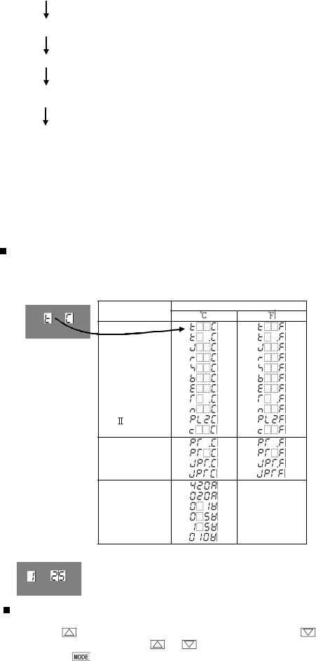
Turn the power supply to the instrument on.
For approx. 3 seconds after the power is turned on, the MEMO/STEP display is turned off and the PV/SV display indicates sensor input characters and temperature unit. (Table 5.2-1)
During this time, all outputs and LED indicators are in an OFF status. (Table 5.2-1)
Sensor input |
PV/SV display |
|
|
K |
|
J |
|
R |
|
S |
|
B |
|
E |
|
T |
|
N |
|
PL- |
|
C (W/Re5-26) |
|
Pt100 |
|
JPt100 |
|
4 to 20mA DC |
|
0 to 20mA DC |
|
0 to 1V DC |
|
0 to 5V DC |
|
1 to 5V DC |
|
0 to 10V DC |
|
After that, the following is indicated.
The MEMO/STEP display indicates a memory number. The PV/SV display indicates an input value (e.g. room temperature). This is the PV/SV display mode.
Basic operation for initial setting
Initial setting is conducted in Auxiliary function setup mode 2. To go to Auxiliary function setup mode 2,
press the |
key for approx. 3 seconds while holding down the |
key in the PV/SV display mode. |
||
Set or select the values with the |
or |
key. |
|
|
Pressing the |
key registers the values and goes to the next item. |
|
||
8

Display used for explaining setting items
Setting items (Section “5.2 Initial setting” and setting modes from Section 6.1 to 6.3) are explained as follows. (e.g.) Input type selection
 means that input type characters
  and selected value
  (K –200 to 1370
 ) are indicated in turn.
Auxiliary function setting mode 2
Display |
Item, Function, Setting range |
Default value |
|
Input type selection |
K (-200 to 1370 ) |
|
• The input type can be selected from thermocouple (10 types), |
|
|
RTD (2 types), DC current (2 types) and DC voltage (4 types). |
|
|
The unit / can be selected as well. |
|
•When changing the input from DC voltage to other inputs, remove the sensor connected to this controller first, then change for the input. If the input is changed with the sensor connected, the input circuit may break.
: |
K |
|
-200 to 1370 |
|
: |
|
|
-199.9 to 400.0 |
|
: |
J |
|
-200 to 1000 |
|
: |
R |
|
0 to 1760 |
|
: |
S |
|
0 to 1760 |
|
: |
B |
|
0 to 1820 |
|
: |
E |
|
-200 to 800 |
|
: |
T |
|
-199.9 to 400.0 |
|
: |
N |
|
-200 to 1300 |
|
: |
PL- |
|
0 to 1390 |
|
: |
C (W/Re5-26) |
|
0 to 2315 |
|
: |
Pt100 |
|
-199.9 to 850.0 |
|
: |
JPt100 |
|
-199.9 to 500.0 |
|
: |
Pt100 |
|
-200 to 850 |
|
: |
JPt100 |
|
-200 to 500 |
|
: |
K |
|
-320 to 2500 |
|
: |
|
|
-199.9 to 750.0 |
|
: |
J |
|
-320 to 1800 |
|
: |
R |
|
0 to 3200 |
|
: |
S |
|
0 to 3200 |
|
: |
B |
|
0 to 3300 |
|
: |
E |
|
-320 to 1500 |
|
: |
T |
|
-199.9 to 750.0 |
|
: |
N |
|
-320 to 2300 |
|
: |
PL- |
|
0 to 2500 |
|
: |
C (W/Re5-26) |
|
0 to 4200 |
|
: |
Pt100 |
|
-199.9 to 999.9 |
|
: |
JPt100 |
|
-199.9 to 900.0 |
|
: |
Pt100 |
|
-300 to 1500 |
|
: |
JPt100 |
|
-300 to 900 |
|
: |
4 to 20mA DC |
|
-1999 to 9999 |
|
: |
0 to 20mA DC |
|
-1999 to 9999 |
|
: |
0 to 1V DC |
|
-1999 to 9999 |
|
: |
0 to 5V DC |
|
-1999 to 9999 |
|
: |
1 to 5V DC |
|
-1999 to 9999 |
|
: |
0 to 10V DC |
|
-1999 to 9999 |
|
Scaling high limit setting |
|
1370 |
||
•Sets scaling high limit value.
•Setting range: Scaling low limit value to input range high
limit value
Scaling low limit setting |
-200 |
•Sets scaling low limit value.
•Setting range: Input range low limit value to scaling high limit
value
9
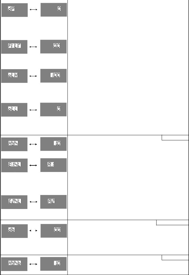
Decimal point place selection |
No decimal point |
•Selects decimal point place.
•Available only for DC input
• : No decimal point
 : 1 digit after decimal point

 : 2 digits after decimal point
 : 3 digits after decimal point
PV filter time constant setting |
0.0 seconds |
• Sets PV filter time constant.
Input fluctuation due to the noise can be reduced.
If the value is set too large, it affects control result due to the delay of response.
• Setting range: 0.0 to 10.0 seconds
OUT1 (Heating) high limit setting |
100% |
• Sets OUT1 (Heating) high limit value.
Not available if OUT1 (Heating) is ON/OFF action
•If Heating/Cooling control option is added, OUT1 terminals are used for Heating output terminals.
•Setting range: OUT1 (Heating) low limit value to 105%
(Setting higher than 100% is effective to DC current output type)
OUT1 (Heating) low limit setting |
0% |
• Sets OUT1 (Heating) low limit value.
Not available if OUT1 (Heating) is ON/OFF action
•If Heating/Cooling control option is added, OUT1 terminals are used for Heating output terminals.
•Setting range: –5% to OUT1 (Heating) high limit value (Setting less than 0% is effective to DC current output type)
OUT1 (Heating) ON/OFF action hysteresis setting 1.0
•Sets ON/OFF action hysteresis for OUT1 (Heating).
•Available only when OUT1 (Heating) is ON/OFF action
•Setting range: 0.1 to 100.0 (
( ), or 1 to 1000
EV1 output selection |
A1 output |
•Selects a function for EV1 output terminals.
•Not available if Heating/Cooling control option is added, since EV1 terminals are used for Cooling output terminals.
• : A1 output
 : A2 output
 : Common to A1 and A2 output
EV2 output selection |
A2 output |
•Selects a function for EV2 output terminals.
•Not available if Serial communication option is added
• : A1 output
 : A2 output
 : Common to A1 and A2 output
Overlap band/Dead band setting 0.0
• Sets the overlap band or dead band for OUT1 (Heating side) and OUT2 (Cooling side).
+ set value: Dead band
–set value: Overlap band
•Available only when the Heating/Cooling control option is added
•Setting range: –100.0 to 100.0 (
( ), or 1 to 1000
OUT2 (Cooling) ON/OFF action hysteresis setting 1.0
•Sets ON/OFF action hysteresis for OUT2 (Cooling side).
•Available only when the Heating/Cooling control option is added
•Setting range: 0.1 to 100.0 (
( ), or 1 to 1000
10
 Loading...