


 Loading...
Model No. KV-S3065CL / KV-S3065CW
These instructions contain information on operating the scanner. Before reading these instructions, please read the installation manual enclosed with this unit.
Please carefully read these instructions, the enclosed installation manual and maintenance manual. Keep all documentation in a safe place for future reference.
Keep the CD-ROM in the protective case. Do not expose the CD-ROM to direct sunlight or extreme heat and do not scratch or smudge the surface of the CD-ROM.

Thank you for purchasing a Panasonic “High Speed Color Scanner.”
≥Panasonic supports your imaging needs with a reliable and easy to use document scanner.
≥Panasonic has developed Panasonic Image Enhancement Technology to improve the quality of your scanned images even beyond the quality of your original document.
∫System requirements
When using the scanner, the required host computer conditions are as follows.
|
|
|
SCSI Connection |
USB Connection |
|
|
|
|
|
|
|
CPU |
Minimum |
Pentium® III, 1 GHz |
|
||
Recommended |
Pentium 4, 2 GHz or higher |
|
|||
|
|
|
|||
Memory |
Minimum |
256 MB |
|
||
Recommended |
512 MB or higher |
|
|||
|
|
|
|||
|
|
|
|
|
|
OS |
Windows® 98*1 |
/ Windows NT ®*3 4.0 / |
Windows 98 / Windows 2000 / |
||
Windows 2000*4 / Windows Me*2 / Windows XP*5 |
Windows Me / Windows XP |
||||
|
|
||||
Display |
1024k768 dots or more, 65536 colors or more |
|
|||
|
|
|
|
|
|
Interface |
SCSI III |
|
USB 2.0 |
||
Recommended SCSI board |
|
||||
|
|
Adaptec SCSI 2930U / 2940U / 29160N /19160 |
|
||
|
|
|
|
||
*1 |
Microsoft® Windows 98 operating system (hereafter Windows 98) |
||||
*2 |
Microsoft Windows Millennium Edition operating system (hereafter Windows Me) |
||||
*3 |
Microsoft Windows NT operating system (hereafter Windows NT) |
||||
*4 |
Microsoft Windows 2000 operating system (hereafter Windows 2000) |
||||
*5 |
Microsoft Windows XP operating system (hereafter Windows XP) |
||||
§1 GB or more free space is required in the HDD.
§Color images larger than A3 size cannot be scanned in 600 dpi on Windows 98 or Windows Me. A large size color image may not be scanned in high resolution depending on a computer system or application.
§The scanning speed differs depending on the host computer operating environment or application.
§Windows NT 4.0 does not support USB interface.
§For Windows NT 4.0, you must install the ASPI layer software that the SCSI board vender provides.
§Use USB 2.0 interface because scanning speed of USB 1.1 interface is slow.
§If you connect the scanner to a USB hub, it is not guaranteed to work.
§When using the scanner with other SCSI devices connected by daisy chain connection, it is not guaranteed to work.
As an ENERGY STAR® Partner, Panasonic has determined that this product meets the ENERGY STAR guidelines for energy efficiency.
(ENERGY STAR and the ENERGY STAR certification mark are registered US marks.)
≥Microsoft, Windows and Windows NT are either registered trademarks or trademarks of Microsoft Corporation in the United States and/or other countries.
≥ISIS is a registered trademark of Pixel Translations, a division of Captiva Software Corporation.
≥Pentium is a trademark or registered trademark of Intel Corporation or its subsidiaries in the United States and other countries.
≥Adaptec is a registered trademark of Adaptec, Inc.
≥Each company’s name or company product name is each company’s trademark or registered trademark.
The information given in these Operating Instructions is subject to change without notice.
2

Before
You Start
Table of Contents
Page
Notice . . . . . . . . . . . . . . . . . . . . . . . . . . . . . . . . . . . . . . . . . . . . . . . 4 Precautions. . . . . . . . . . . . . . . . . . . . . . . . . . . . . . . . . . . . . . . . . . . 7
Component Identification . . . . . . . . . . . . . . . . . . . . . . . . . . . . . . 10
≥Power turn-on sequence . . . . . . . . . . . . . . . . . . . . . . . . . . . . . . . . . . . . . . . . 11 ≥About LED . . . . . . . . . . . . . . . . . . . . . . . . . . . . . . . . . . . . . . . . . . . . . . . . . . . 11 ≥About the SCSI setting (Not required for USB connection) . . . . . . . . . . . . . . 12
Loading Documents. . . . . . . . . . . . . . . . . . . . . . . . . . . . . . . . . . . 13
≥When scanning multiple sheets . . . . . . . . . . . . . . . . . . . . . . . . . . . . . . . . . . . 14
Paper Feed Settings. . . . . . . . . . . . . . . . . . . . . . . . . . . . . . . . . . . 17
Operation
≥Selecting the paper path for scanned document . . . . . . . . . . . . . . . . . . . . . . |
17 |
≥Setting the ADF / manual feed selector . . . . . . . . . . . . . . . . . . . . . . . . . . . . . |
17 |
Others . . . . . . . . . . . . . . . . . . . . . . . . . . . . . . . . . . . . . . . . . . . . . . 18
≥How to use the control sheet and separation sheet . . . . . . . . . . . . . . . . . . . . 18
Changing the Reference Plate Setting . . . . . . . . . . . . . . . . . . . . |
19 |
≥Reference plate setting . . . . . . . . . . . . . . . . . . . . . . . . . . . . . . . . . . . . . . . . . |
19 |
Clearing Paper Jams . . . . . . . . . . . . . . . . . . . . . . . . . . . . . . . . . . 21
≥Removing paper jams from the scanner . . . . . . . . . . . . . . . . . . . . . . . . . . . . 21 ≥Removing paper jams from the exit path . . . . . . . . . . . . . . . . . . . . . . . . . . . . 21
Care
and
Maintenance
Cleaning the Unit . . . . . . . . . . . . . . . . . . . . . . . . . . . . . . . . . . . . . |
22 |
≥Outside of the scanner . . . . . . . . . . . . . . . . . . . . . . . . . . . . . . . . . . . . . . . . . . |
22 |
≥Inside the scanner . . . . . . . . . . . . . . . . . . . . . . . . . . . . . . . . . . . . . . . . . . . . . |
22 |
≥Roller cleaning paper . . . . . . . . . . . . . . . . . . . . . . . . . . . . . . . . . . . . . . . . . . . |
22 |
≥Cleaning the rollers . . . . . . . . . . . . . . . . . . . . . . . . . . . . . . . . . . . . . . . . . . . . |
23 |
≥Cleaning the sensors, reflectors, double feed detectors and image sensor |
|
covers. . . . . . . . . . . . . . . . . . . . . . . . . . . . . . . . . . . . . . . . . . . . . . . . . . . . . . . |
25 |
Replacing Consumables . . . . . . . . . . . . . . . . . . . . . . . . . . . . . . . 27
≥Replacing paper feed roller module . . . . . . . . . . . . . . . . . . . . . . . . . . . . . . . . 27 ≥Replacing retard roller module . . . . . . . . . . . . . . . . . . . . . . . . . . . . . . . . . . . . 29
Shading Adjustment. . . . . . . . . . . . . . . . . . . . . . . . . . . . . . . . . . . 32
Repacking Instructions . . . . . . . . . . . . . . . . . . . . . . . . . . . . . . . . 33
Specifications . . . . . . . . . . . . . . . . . . . . . . . . . . . . . . . . . . . . . . . . 34
Appendix Troubleshooting . . . . . . . . . . . . . . . . . . . . . . . . . . . . . . . . . . . . . . 36
Index . . . . . . . . . . . . . . . . . . . . . . . . . . . . . . . . . . . . . . . . . . . . . . . 38
3

Notice
English
WARNING:
TO PREVENT FIRE OR SHOCK HAZARD, DO NOT EXPOSE THIS PRODUCT TO RAIN OR
ANY TYPE OF MOISTURE.
THE SOCKET-OUTLET MUST BE NEAR THIS EQUIPMENT AND MUST BE EASILY
ACCESSIBLE.
The product should be used only with a power cord that is supplied by the manufacturer.
Power Source
WARNING
≥(220-240 V equipment)
A certified power supply cord has to be used with this equipment. The relevant national installation and/or
equipment regulations shall be considered. A certified power supply cord not lighter than ordinary polyvinyl chloride flexible cord according to IEC 60227 (designation H05VV-F 3G 1.0 mm2).
Roller cleaning paper precautions
Before using the roller cleaning paper, please read these instructions completely. Keep these instructions for future reference.
WARNING
•Do not drink or inhale the roller cleaning paper fluid including isopropyl alcohol.
•The roller cleaning paper may be harmful to sensitive skin. Please use protective gloves.
•Do not use the roller cleaning paper near a heater or open flame.
•Do not store the roller cleaning paper in direct sunlight or in a place with temperature over 40 oC (104 oF).
•Only use the roller cleaning paper to clean the rollers and scanning area.
•If you need more information about the roller cleaning paper, please refer to the Material Safety Data Sheet (MSDS).
•Please ask your Panasonic sales company about obtaining the Material Safety Data Sheet.
KEEP AWAY FROM FIRE.
Federal Communications Commission Requirements
(For United States only)
Note: This equipment has been tested and found to comply with the limits for a Class A digital device, pursuant to part 15 of the FCC Rules. These limits are designed to provide reasonable protection against harmful interference when the equipment is operated in a commercial environment. This equipment generates, uses, and can radiate radio frequency energy and, if not installed and used in accordance with the instruction manual, may cause harmful interference to radio communications. Operation of this equipment in a residential area is likely to cause harmful interference in which case the user will be required to correct the interference at his own expense.
FCC Warning: To assure continued FCC compliance, the user must use only shielded interface cable and the provided power supply cord. Also, any unauthorized changes or modifications to this equipment would void the user’s authority to operate this device.
4
Notice
(For United Kingdom only)
For your safety please read the following text carefully.
This appliance is supplied with a moulded three pin mains plug for your safety and convenience.
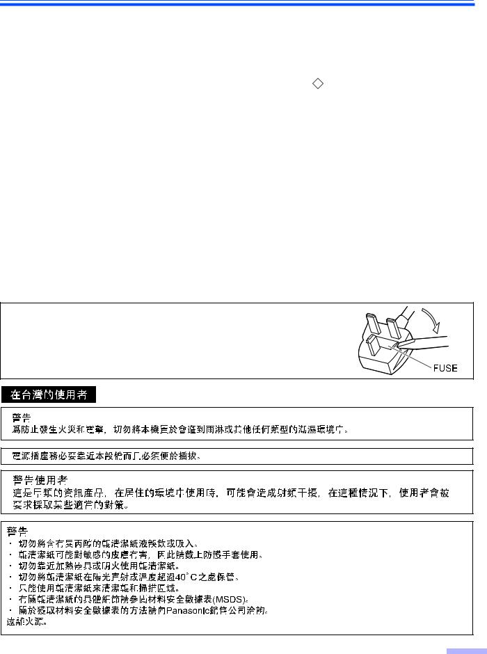
A 5 amp. fuse is fitted in this plug. Should the fuse need to be replaced, please ensure that the replacement fuse has a rating of 5 amps. and that it is approved by ASTA or BSI to BS1362. Check for the ASTA mark ASA or the BSI mark  on the body of the fuse. If the plug contains a removable fuse cover you must ensure that it is refitted when the fuse is replaced. If you lose the fuse cover the plug must not be used until a replacement cover is obtained. A replacement fuse cover can be purchased from your local Panasonic Dealer.
If the fitted moulded plug is unsuitable for the socket outlet in your home then the fuse should be removed and the plug cut off and disposed of safely.
There is danger of severe electrical shock if the cut off plug is inserted into any 13 amp. socket.
If a new plug is to be fitted please observe the wiring code as shown below. If in any doubt please consult a qualified electrician. WARNING: This appliance must be earthed.
IMPORTANT: The wires in this mains lead are coloured in accordance with the following code.
Green-and-Yellow |
: Earth |
Blue |
: Neutral |
Brown |
: Live |
As the colours of the wire in the mains lead of this appliance may not correspond with the coloured markings identifying the terminals in your plug, proceed as follows.
The wire which is coloured Green-and-Yellow must be connected to the terminal in the plug which is marked with the letter E or by
the Earth symbol |
|
|
|
|
|
|
or coloured Green-and-Yellow. |
The wire which is coloured Blue must be connected to the terminal in the plug which is marked with the letter N or coloured Black. The wire which is coloured Brown must be connected to the terminal in the plug which is marked with the letter L or coloured Red.
How to replace the fuse:
Open the fuse compartment with a screwdriver and replace the fuse.
5
Notice
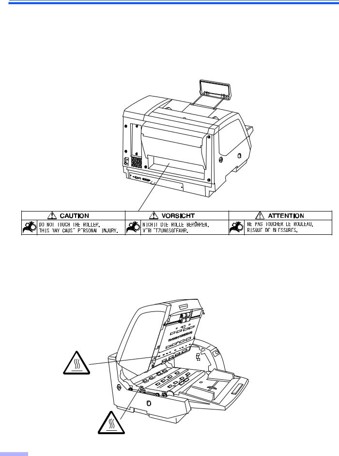
Caution Labels
6

Precautions
The following precautions are recommended to extend the life of the unit:
Prior to scanning, remove all staples and paper clips from pages.
Do not place any liquids near the unit.
—Accidental spillage of liquid into the unit may cause severe damage. If this occurs, turn the unit off, unplug the power cord and call for service.
Do not place books, paper, or other items on the unit.
Do not place the unit in an area where there is a lot of |
Do not leave the power cord plugged into the AC outlet |
smoke, dust, chemical fumes or vibration. |
if the unit will not be used for an extended period. |
Ex: 
Ex: Thinner
Do not place the unit on an uneven or unstable surface. Do not disassemble the unit.
This will void your warranty.
Do not insert your fingers into the back opening in the When carrying the unit, please hold both side grips. scanner.

 Grip
Grip
(On both sides)
≥Special care should be taken to protect the unit if it is used in a less than optimum environment, such as a dusty or sandy area.
7
Precautions
Operating Environment
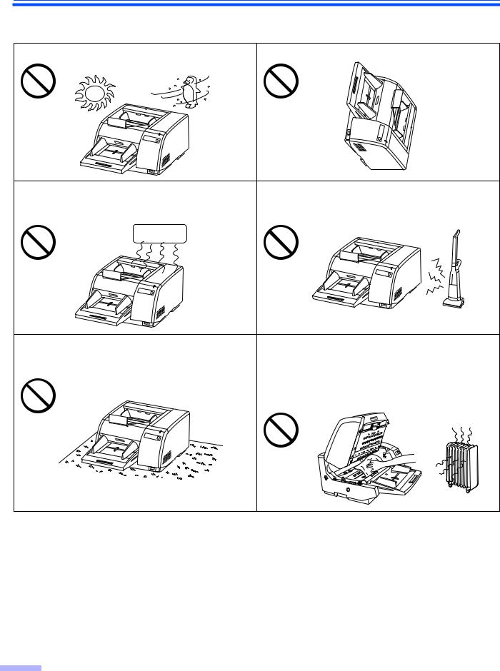
Do not place the unit in direct sunlight or in a cold draft. Do not operate or place the unit in a vertical position.
Hot |
Cold |
Do not place the unit near a heating appliance or an air |
Do not place the unit near other appliances which gen- |
||||
conditioning vent. Do not place the unit in a room with |
erate large electrical noise. |
||||
extremely high or low humidity. |
|
||||
|
|
|
|
|
|
|
|
|
|
|
|
|
|
|
|
|
|
|
|
|
|
|
|
|
|
|
|
|
|
|
|
|
|
|
|
|
|
|
|
|
|
|
|
|
|
|
|
|
|
|
|
|
|
|
|
|
|
|
|
|
|
|
|
|
|
|
|
|
|
|
|
|
|
|
|
|
|
Do not place the unit on a carpet. (Static electricity can |
Do not drink or inhale the included roller cleaning paper |
cause the unit to malfunction.) |
fluid. |
|
The roller cleaning paper may be harmful to sensitive |
|
skin. Please use protective gloves. |
|
Do not use the roller cleaning paper near a heater or |
|
open flame. This may cause a fire. |
≥Power Source
≥Use a voltage level that does not vary more than d10% from the voltage level marked on the nameplate (located on the back side of the scanner).
≥Do not use an extension cord.
≥This scanner should be connected to a grounded outlet.
≥Do not use a line conditioner, transient suppressor or surge protector.
8
Precautions
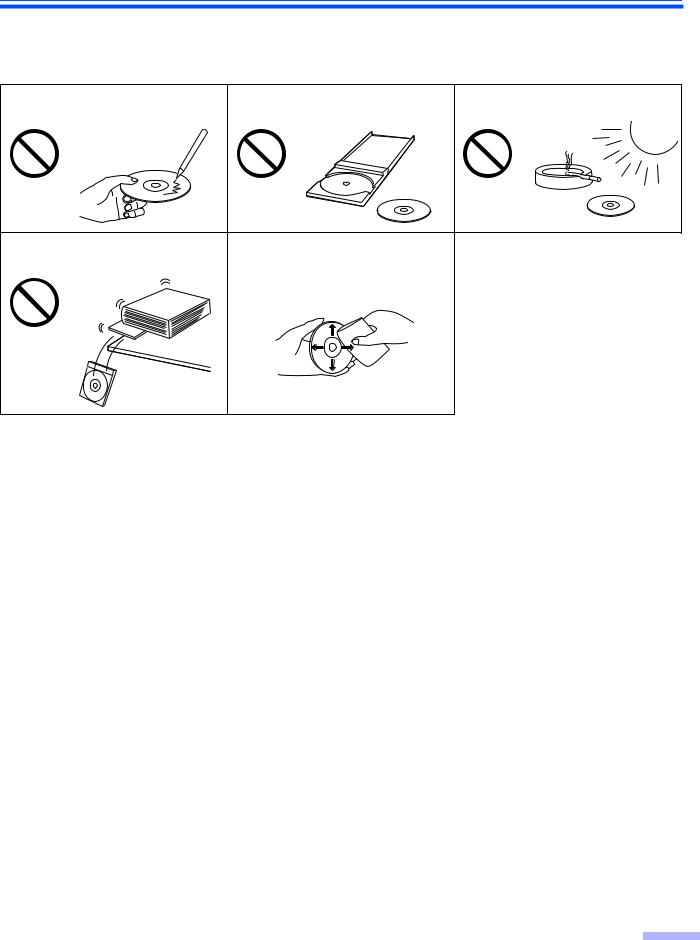
∫CD-ROM
To prevent the CD-ROMs from accidental damages:
Do not touch or write on the surface |
Do not leave the disc out of its |
Do not leave the disc in direct |
of the disc. |
protective case. |
sunlight or near heat sources. |
Do not place heavy objects on the disc case or drop the case.
To clean the disc, hold the disc by its edges and wipe it from the center to the edges with a dry, soft cloth.
9
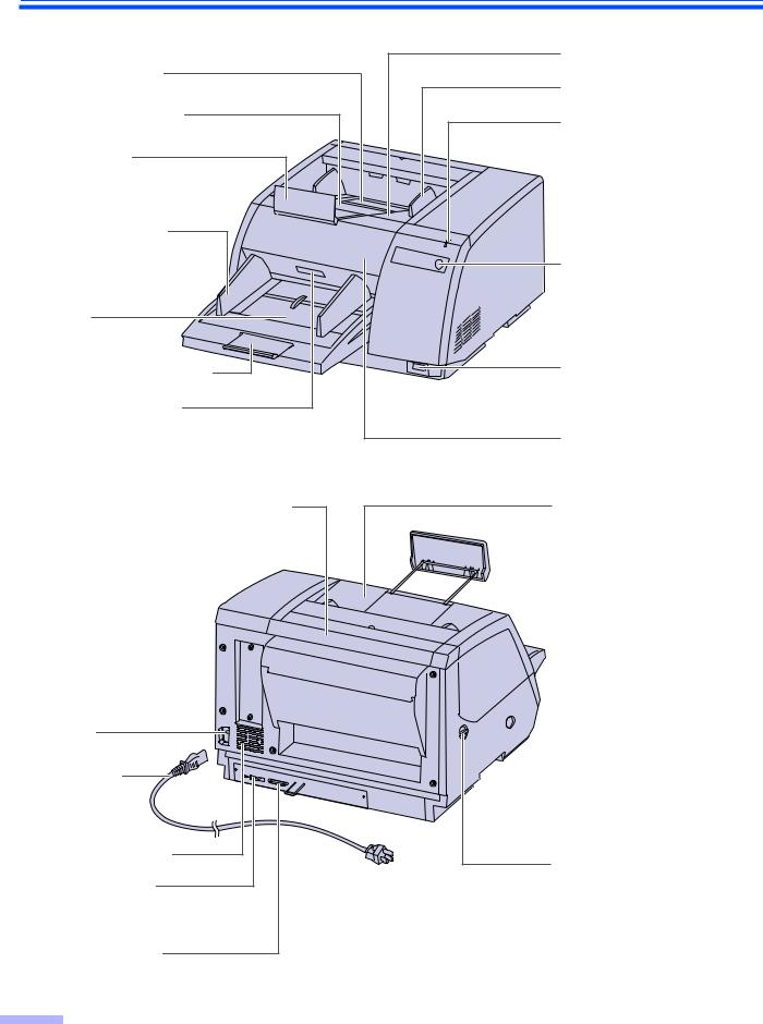
Component Identification
Exit substopper |
Exit extension tray |
Exit stopper |
Document guide
Hopper |
Hopper extension tray |
Front door release |
Inside the front door.
Post-imprinter door (Back door)
Used for attaching optional imprinter unit and ink cartridge.
An imprinter unit installed here is called a post-imprinter.
AC inlet
Power cord
Power cord shown on the figure is for 100–200 V.
Fan exhaust vent
USB connector
Used to connect the scanner unit to the host computer.
SCSI connector
Used to connect the scanner unit to the host computer.
Exit tray
Exit document guide
Power indicator
When the power is turned on, the green indicator lights. When an error occurs, the indicator will change to red, and light steadily or flash.
STOP/START button
Used to stop or start scanning a document.
Power switch
[ : on position
± : off position
Front door
Pre-imprinter door (Exit tray)
Used for attaching optional imprinter unit and ink cartridge. An imprinter unit installed here is called a pre-imprinter.
 ADF / manual feed selector
To prevent double feeding, adjust the selector to feed the scanning document properly. (Refer to page 17.)
Paper path selector
Used to change the scanning document’s path direction (front side/back side).
(Refer to page 17.)
10
|
Component Identification |
|
∫Power turn-on sequence |
LED |
|
1 Turn on the power of the scanner. |
||
|
||
≥The LED will now light. |
|
|
Turn on the power of the host |
|
|
2 computer after scanner’s LED stays |
|
|
green. |
|
|
≥In case of the USB connection, the host |
|
|
computer recognizes the scanner auto- |
|
|
matically when the scanner is powered on |
Power switch |
|
even after the host computer is powered |
|
|
on. |
|
∫About LED
LED indicates the status of the scanner as follows:
LED light |
Status |
|
|
Green |
Ready to scan or scanning |
|
|
Green (flashing) |
Sleep mode |
|
|
Orange |
Ready to scan or scanning with warning *1 |
|
|
Orange (flashing) |
Initializing |
|
Sleeping with warning *1 |
|
|
Red |
An error occurred *2 |
|
|
*1: The rollers need to be cleaned or replaced.
Refer to Maintenance Manual or Operating Instructions (CD-ROM) for the way of cleaning or replacing the rollers.
*1, *2: Check the status of the scanner using the User Utility. The User Utility is included in the CD-ROM.
11
Component Identification
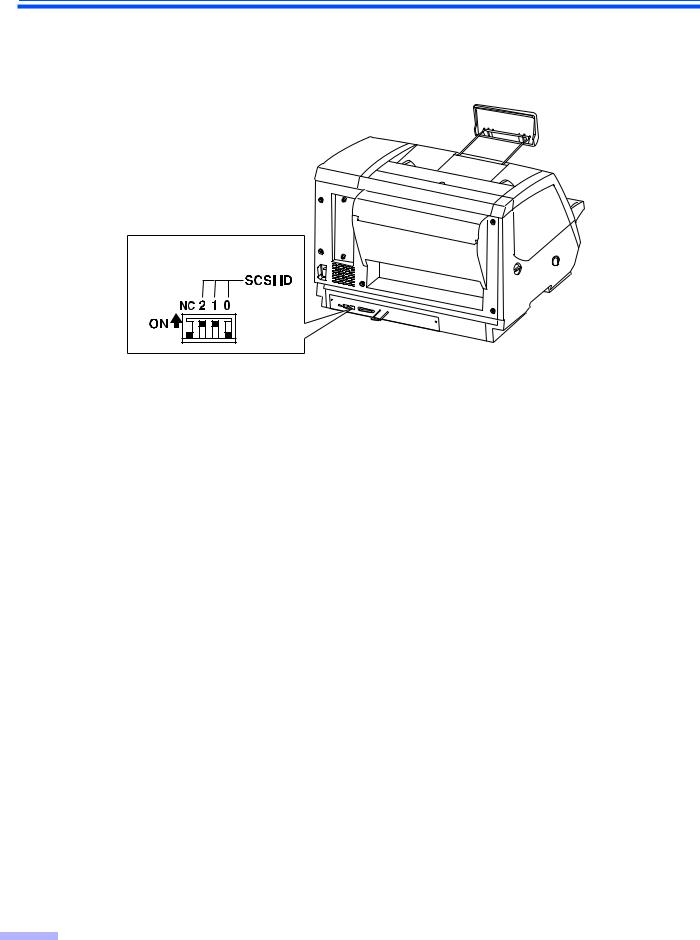
∫About the SCSI setting (Not required for USB connection)
When connecting the scanner to a SCSI chain using a SCSI cable, perform the SCSI ID setting correctly. The scanner is provided with a DIP switch for the SCSI ID No. setting.
DIP switch
SCSI ID Setting
ID No. |
|
Switch |
|
|
Remarks |
|
|
|
|
||
#2 |
#1 |
|
#0 |
||
|
|
|
|||
|
|
|
|
|
|
0 |
OFF |
OFF |
OFF |
|
|
|
|
|
|
|
|
1 |
OFF |
OFF |
ON |
|
|
|
|
|
|
|
|
2 |
OFF |
ON |
OFF |
|
|
|
|
|
|
|
|
3 |
OFF |
ON |
ON |
|
|
|
|
|
|
|
|
4 |
ON |
OFF |
OFF |
|
|
|
|
|
|
|
|
5 |
ON |
OFF |
ON |
|
|
|
|
|
|
|
|
6 |
ON |
ON |
OFF |
|
Default setting |
|
|
|
|
|
|
7 |
ON |
ON |
ON |
|
|
|
|
|
|
|
|
12
Loading...