


Manual No.
I63E-EN-01
VS mini J7
Compact General Purpose Inverter
USER’S Manual

Thank you for choosing this VARISPEED J7-series product. Proper use and handling of the product will ensure proper product performance, will lengthen product life, and may prevent possible accidents. Please read this manual thoroughly and handle and operate the product with care.
1.To ensure safe and proper use of the OMRON-YASKAWA Inverters, please read this USER’S MANUAL (Cat. No. I63-EN-01) to gain sufficient knowledge of the devices, safety information, and precautions before actual use.
2.The products are illustrated without covers and shieldings for closer look in this USER’S MANUAL. For actual use of the products, make sure to use the covers and shieldings as specified.
3.This USER’S MANUAL and other related user’s manuals are to be delivered to the actual end users of the products.
4.Please keep this manual close at hand for future reference.
5.If the product has been left unused for a long time, please inquire at our sales representative.
NOTICE
1.This manual describes the functions of the product and relations with other products. You should assume that anything not described in this manual is not possible.
2.Although care has been given in documenting the product, please contact your OMRON representative if you have any suggestions on improving this manual.
3.The product contains potentially dangerous parts under the cover. Do not attempt to open the cover under any circumstances. Doing so may result in injury or death and may damage the product. Never attempt to repair or disassemble the product.
4.We recommend that you add the following precautions to any instruction manuals you prepare for the system into which the product is being installed.
•Precautions on the dangers of high-voltage equipment.
•Precautions on touching the terminals of the product even after power has been turned OFF. (These terminals are live even with the power turned OFF.)
5.Specifications and functions may be changed without notice in order to improve product performance.
Items to Check Before Unpacking
Check the following items before removing the product from the package:
•Has the correct product been delivered (i.e., the correct model number and specifications)?
•Has the product been damaged in shipping?
•Are any screws or bolts loose?
II

Notice
!DANGER
!WARNING
!Caution
OMRON-YASKAWA products are manufactured for use according to proper procedures by a qualified operator and only for the purposes described in this manual.
The following conventions are used to indicate and classify precautions in this manual. Always heed the information provided with them. Failure to heed precautions can result in injury to people or damage to property.
Indicates an imminently hazardous situation which, if not avoided, will result in death or serious injury. Additionally, there may be severe property damage.
Indicates a potentially hazardous situation which, if not avoided, could result in death or serious injury. Additionally, there may be severe property damage.
Indicates a potentially hazardous situation which, if not avoided, may result in minor or moderate injury, or property damage.
OMRON-YASKAWA Product References
All OMRON-YASKAWA products are capitalized in this manual. The word “Unit” is also capitalized when it refers to an OMRON-YASKAWA product, regardless of whether or not it appears in the proper name of the product.
The abbreviation “Ch,” which appears in some displays and on some OMRON-YASKAWA products, often means “word” and is abbreviated “Wd” in documentation in this sense.
The abbreviation “PC” means Programmable Controller and is not used as an abbreviation for anything else.
Visual Aids
The following headings appear in the left column of the manual to help you locate different types of information.
Note Indicates information of particular interest for efficient and convenient operation of the product.
III

General Precautions
!WARNING
!WARNING
!WARNING
!WARNING
!Caution
!Caution
!Caution
!Caution
!Caution
Observe the following precautions when using the VARISPEED Inverters and peripheral devices.
This manual may include illustrations of the product with protective covers removed in order to describe the components of the product in detail. Make sure that these protective covers are on the product before use.
Consult your OMRON-YASKAWA representative when using the product after a long period of storage.
Do not touch the inside of the Inverter. Doing so may result in electrical shock.
Operation, maintenance, or inspection must be performed after turning OFF the power supply, confirming that the CHARGE indicator (or status indicators) are OFF, and after waiting for the time specified on the front cover. Not doing so may result in electrical shock.
Do not damage, pull on, apply stress to, place heavy objects on, or pinch the cables. Doing so may result in electrical shock.
Do not touch the rotating parts of the motor under operation. Doing so may result in injury.
Do not modify the product. Doing so may result in injury or damage to the product.
Do not store, install, or operate the product in the following places. Doing so may result in electrical shock, fire or damage to the product.
•Locations subject to direct sunlight.
•Locations subject to temperatures or humidity outside the range specified in the specifications.
•Locations subject to condensation as the result of severe changes in temperature.
•Locations subject to corrosive or flammable gases.
•Locations subject to exposure to combustibles.
•Locations subject to dust (especially iron dust) or salts.
•Locations subject to exposure to water, oil, or chemicals.
•Locations subject to shock or vibration.
Do not touch the Inverter radiator, regenerative resistor, or Servomotor while the power is being supplied or soon after the power is turned OFF. Doing so may result in a skin burn due to the hot surface.
Do not conduct a dielectric strength test on any part of the Inverter. Doing so may result in damage to the product or malfunction.
Take appropriate and sufficient countermeasures when installing systems in the following locations. Not doing so may result in equipment damage.
•Locations subject to static electricity or other forms of noise.
•Locations subject to strong electromagnetic fields and magnetic fields.
•Locations subject to possible exposure to radioactivity.
•Locations close to power supplies.
IV

Transportation Precautions
!Caution
!Caution
!Caution
Do not hold by front cover or panel , instead, hold by the radiation fin (heat sink) while transporting the product. Doing so may result in injury.
Do not pull on the cables. Doing so may result in damage to the product or malfunction.
Use the eye-bolts only for transporting the Inverter. Using them for transporting the machinery may result in injury or malfunction.
Installation Precautions
Provide an appropriate stopping device on the machine side to secure safety. ! WARNING (A holding brake is not a stopping device for securing safety.) Not doing so
may result in injury.
!WARNING
!Caution
!Caution
!Caution
Wiring Precautions
!WARNING
!WARNING
!WARNING
!WARNING
!Caution
!Caution
!Caution
!Caution
!Caution
!Caution
Provide an external emergency stopping device that allows an instantaneous stop of operation and power interruption. Not doing so may result in injury.
Be sure to install the product in the correct direction and provide specified clearances between the Inverter and control panel or with other devices. Not doing so may result in fire or malfunction.
Do not allow foreign objects to enter inside the product. Doing so may result in fire or malfunction.
Do not apply any strong impact. Doing so may result in damage to the product or malfunction.
Wiring must be performed only after confirming that the power supply has been turned OFF. Not doing so may result in electrical shock.
Wiring must be performed by authorized personnel. Not doing so may result in electrical shock or fire.
Be sure to confirm operation only after wiring the emergency stop circuit. Not doing so may result in injury.
Always connect the ground terminals to a ground of 100 W or less for the 200V AC class, or 10 W or less for the 400-V AC class. Not connecting to a proper ground may result in electrical shock.
Install external breakers and take other safety measures against shortcircuiting in external wiring. Not doing so may result in fire.
Confirm that the rated input voltage of the Inverter is the same as the AC power supply voltage. An incorrect power supply may result in fire, injury, or malfunction.
Connect the Braking Resistor and Braking Resistor Unit as specified in the manual. Not doing so may result in fire.
Be sure to wire correctly and securely. Not doing so may result in injury or damage to the product.
Be sure to firmly tighten the screws on the terminal block. Not doing so may result in fire, injury, or damage to the product.
Do not connect an AC power to the U, V, or W output. Doing so may result in damage to the product or malfunction.
V

Operation and Adjustment Precautions
Turn ON the input power supply only after mounting the front cover, terminal ! WARNING covers, bottom cover, Operator, and optional items. Not doing so may result in
electrical shock.
Do not remove the front cover, terminal covers, bottom cover, Operator, or ! WARNING optional items while the power is being supplied. Doing so may result in
electrical shock or damage to the product.
!WARNING
!WARNING
!WARNING
Do not operate the Operator or switches with wet hands. Doing so may result in electrical shock.
Do not touch the inside of the Inverter. Doing so may result in electrical shock.
Do not come close to the machine when using the error retry function because the machine may abruptly start when stopped by an alarm. Doing so may result in injury.
Do not come close to the machine immediately after resetting momentary ! WARNING power interruption to avoid an unexpected restart (if operation is set to be
continued in the processing selection function after momentary power interruption is reset). Doing so may result in injury.
Provide a separate emergency stop switch because the STOP Key on the ! WARNING Operator is valid only when function settings are performed. Not doing so may
result in injury.
Be sure to confirm that the RUN signal is turned OFF before turning ON the ! WARNING power supply, resetting the alarm, or switching the LOCAL/REMOTE selector.
Doing so while the RUN signal is turned ON may result in injury.
! |
Caution |
Be sure to confirm permissible ranges of motors and machines before |
|
operation because the Inverter speed can be easily changed from low to high. |
|||
|
|
||
|
|
Not doing so may result in damage to the product. |
!Caution
!Caution
!Caution
Provide a separate holding brake when necessary. Not doing so may result in injury.
Do not perform a signal check during operation. Doing so may result in injury or damage to the product.
Do not carelessly change settings. Doing so may result in injury or damage to the product.
VI
Maintenance and Inspection Precautions
!WARNING
!WARNING
!WARNING
!WARNING
!Caution
!Caution
Do not touch the Inverter terminals while the power is being supplied.
Maintenance or inspection must be performed only after turning OFF the power supply, confirming that the CHARGE indicator (or status indicators) is turned OFF, and after waiting for the time specified on the front cover. Not doing so may result in electrical shock.
Maintenance, inspection, or parts replacement must be performed by authorized personnel. Not doing so may result in electrical shock or injury.
Do not attempt to take the Unit apart or repair. Doing either of these may result in electrical shock or injury.
Carefully handle the Inverter because it uses semiconductor elements. Careless handling may result in malfunction.
Do not change wiring, disconnect connectors, the Operator, or optional items, or replace fans while power is being supplied. Doing so may result in injury, damage to the product, or malfunction.
Warning Labels
Warning labels are pasted on the product as shown in the following illustration. Be sure to follow the instructions given there.
Warning Labels
VII
Contents of Warning
•For CIMR-J7AZ20P1 to 20P7 (0.1 to 0.75 kW) and CIMR-J7AZB0P1 to B0P4 (0.1 to 0.4 kW):
•For CIMR-J7AZ21P5 to A4P0 (1.5 to 4.0 kW), CIMR-J7AZB0P7 to B1P5 (0.75 to 1.5 kW), and CIMR-J7AZ40P2 to 44P0 (0.2 to 3.7 kW):
Checking Before Unpacking
Checking the Product
On delivery, always check that the delivered product is the VARISPEED J7
Inverter that you ordered.
Should you find any problems with the product, immediately contact your nearest local sales representative.
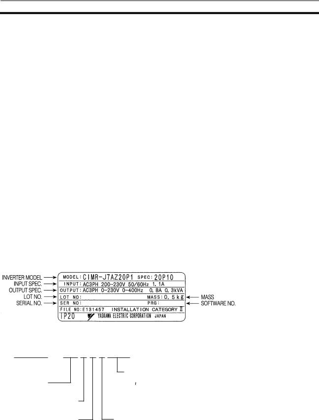
Checking the Nameplate
Checking the Model
C I M R — J 7 A Z 2 0 P 1
Inverter 
J7 series
A:With digital operator (with potentiometer)
Z:European standard specifications
Max. applicable motor output 0P1: 0.1 kW
4P0: 4.0 kW
["P"pointindicates a decimal]
Voltage
B: Single-phase 200 VAC
2: Three-phase 200 VAC
4: Three-phase 400 VAC
VIII

Maximum Applicable Motor Capacity
0P1 |
0.1 |
(0.1) kW |
|
|
|
0P2 |
0.25/0.37 (0.2) kW |
|
|
|
|
0P4 |
0.55 (0.4) kW |
|
|
|
|
0P7 |
1.1 |
(0.75) kW |
|
|
|
1P5 |
1.5 |
(1.5) kW |
|
|
|
2P2 |
2.2 |
(2.2) kW |
|
|
|
4P0 |
4.0 |
(4.0) kW |
|
|
|
|
Note |
The figures in parentheses indicate capacities for motors used outside Japan. |
|
Voltage Class |
|
|
|
|
|
|
|
2 |
Three-phase 200-V AC input (200-V class) |
|
|
|
|
|
|
B |
Single-phase 200-V AC input (200-V class) |
|
|
|
|
|
|
4 |
Three-phase 400-V AC input (400-V class) |
|
|
|
|
|
|
Checking for Damage |
Check the overall appearance and check for damage or scratches resulting |
||
|
|
form transportation. |
|
About this Manual
This manual is divided into the chapters described in the following table. Information is organized by application area to enable you to use the manual more efficiently.
Chapter |
Contents |
|
|
Chapter 1 Overview |
Describes features and nomenclature. |
|
|
Chapter 2 Design |
Provides dimensions, installation methods, wiring methods, peripheral device |
|
design information, and peripheral device selection information. |
|
|
Chapter 3 Preparing for Operation and |
Describes nomenclature and Digital Operator procedures for operating and |
Monitoring |
monitoring Inverters. |
|
|
Chapter 4 Test Run |
Describes the method for controlling a motor through the frequency adjuster on |
|
the front of the Inverter. This can be used for trial operation of the system. |
|
|
Chapter 5 Basic Operation |
Describes basic Inverter control functions for users not familiar with Inverters. |
|
The functions that must be understood to drive a motor with an Inverter are |
|
described. |
|
|
Chapter 6 Advanced Operation |
Describes all of the functions provided by the Inverter. These functions will |
|
enable more advanced applications, and includes functions that will improve |
|
motor control through the Inverter, such as responsiveness (torque character- |
|
istics), increasing speed accuracy, PID control, overtorque detection, and |
|
other functions. |
|
|
Chapter 7 Communications |
Describes the RS-422/485 Communications Unit and the general-purpose |
|
RS-422/485 communications functions provided by the Inverter, including |
|
connection methods. |
|
|
Chapter 8 Maintenance Operations |
Provides maintenance, inspection, and troubleshooting information. |
|
|
Chapter 9 Specifications |
Provides Inverter specifications, as well as the specifications and dimensions of |
|
peripheral devices. |
|
|
Chapter 10 List of Parameters |
Lists basic information on Inverter parameters as a reference for users already |
|
familiar with Inverter operation. Parameters are listed in order with the page |
|
numbers of further information for easy reference. |
|
|
Chapter 11 Using the Inverter for a |
Describes information on using the Inverter for a motor. |
Motor |
|
|
|
Read and Understand this Manual
Please read and understand this manual before using the product. Please consult your OMRON-YASKAWA representative if you have any questions or comments.
IX

Warranty and Limitations of Liability
WARRANTY
OMRON-YASKAWA’s exclusive warranty is that the products are free from defects in materials and workmanship for a period of one year (or other period if specified) from date of sale by OMRON-YASKAWA.
OMRON-YASKAWA MAKES NO WARRANTY OR REPRESENTATION, EXPRESS OR IMPLIED, REGARDING NONINFRINGEMENT, MERCHANTABILITY, OR FITNESS FOR PARTICULAR PURPOSE OF THE PRODUCTS. ANY BUYER OR USER ACKNOWLEDGES THAT THE BUYER OR USER ALONE HAS DETERMINED THAT THE PRODUCTS WILL SUITABLY MEET THE REQUIREMENTS OF THEIR INTENDED USE. OMRON DISCLAIMS ALL OTHER WARRANTIES, EXPRESS OR IMPLIED.
LIMITATIONS OF LIABILITY
OMRON-YASKAWA SHALL NOT BE RESPONSIBLE FOR SPECIAL, INDIRECT, OR CONSEQUENTIAL DAMAGES, LOSS OF PROFITS OR COMMERCIAL LOSS IN ANY WAY CONNECTED WITH THE PRODUCTS, WHETHER SUCH CLAIM IS BASED ON CONTRACT, WARRANTY, NEGLIGENCE, OR STRICT LIABILITY.
In no event shall the responsibility of OMRON-YASKAWA for any act exceed the individual price of the product on which liability is asserted.
IN NO EVENT SHALL OMRON-YASKAWA BE RESPONSIBLE FOR WARRANTY, REPAIR, OR OTHER CLAIMS REGARDING THE PRODUCTS UNLESS OMRON-YASKAWA’S ANALYSIS CONFIRMS THAT THE PRODUCTS WERE PROPERLY HANDLED, STORED, INSTALLED, AND MAINTAINED AND NOT SUBJECT TO CONTAMINATION, ABUSE, MISUSE, OR INAPPROPRIATE MODIFICATION OR REPAIR.
Application Considerations
SUITABILITY FOR USE
OMRON-YASKAWA shall not be responsible for conformity with any standards, codes, or regulations that apply to the combination of products in the customer’s application or use of the products.
At the customer’s request, OMRON-YASKAWA will provide applicable third party certification documents identifying ratings and limitations of use that apply to the products. This information by itself is not sufficient for a complete determination of the suitability of the products in combination with the end product, machine, system, or other application or use.
The following are some examples of applications for which particular attention must be given. This is not intended to be an exhaustive list of all possible uses of the products, nor is it intended to imply that the uses listed may be suitable for the products:
•Outdoor use, uses involving potential chemical contamination or electrical interference, or conditions or uses not described in this manual.
•Nuclear energy control systems, combustion systems, railroad systems, aviation systems, medical equipment, amusement machines, vehicles, safety equipment, and installations subject to separate industry or government regulations.
•Systems, machines, and equipment that could present a risk to life or property.
Please know and observe all prohibitions of use applicable to the products.
NEVER USE THE PRODUCTS FOR AN APPLICATION INVOLVING SERIOUS RISK TO LIFE OR PROPERTY WITHOUT ENSURING THAT THE SYSTEM AS A WHOLE HAS BEEN DESIGNED TO ADDRESS THE RISKS, AND THAT THE OMRON-YASKAWA PRODUCTS ARE PROPERLY RATED AND INSTALLED FOR THE INTENDED USE WITHIN THE OVERALL EQUIPMENT OR SYSTEM.
PROGRAMMABLE PRODUCTS
OMRON-YASKAWA shall not be responsible for the user’s programming of a programmable product, or any consequence thereof.
X
Disclaimers
CHANGE IN SPECIFICATIONS
Product specifications and accessories may be changed at any time based on improvements and other reasons.
It is our practice to change model numbers when published ratings or features are changed, or when significant construction changes are made. However, some specifications of the products may be changed without any notice. When in doubt, special model numbers may be assigned to fix or establish key specifications for your application on your request. Please consult with your OMRON-YASKAWA representative at any time to confirm actual specifications of purchased products.
DIMENSIONS AND WEIGHTS
Dimensions and weights are nominal and are not to be used for manufacturing purposes, even when tolerances are shown.
PERFORMANCE DATA
Performance data given in this manual is provided as a guide for the user in determining suitability and does not constitute a warranty. It may represent the result of OMRON-YASKAWA’s test conditions, and the users must correlate it to actual application requirements. Actual performance is subject to the OMRON-YASKAWA Warranty and Limitations of Liability.
ERRORS AND OMISSIONS
The information in this manual has been carefully checked and is believed to be accurate; however, no responsibility is assumed for clerical, typographical, or proofreading errors, or omissions.
XI

XII
Table of Contents
CHAPTER 1
Overview. . . . . . . . . . . . . . . . . . . . . . . . . . . . . . . . . . . . . . 1
1-1 Function . . . . . . . . . . . . . . . . . . . . . . . . . . . . . . . . . . . . . . . . . . . . . . . . . . . . . . . . 2
1-2 Nomenclature. . . . . . . . . . . . . . . . . . . . . . . . . . . . . . . . . . . . . . . . . . . . . . . . . . . . 3
CHAPTER 2
Design . . . . . . . . . . . . . . . . . . . . . . . . . . . . . . . . . . . . . . . . 5
2-1 Installation . . . . . . . . . . . . . . . . . . . . . . . . . . . . . . . . . . . . . . . . . . . . . . . . . . . . . . 6
2-2 Wiring . . . . . . . . . . . . . . . . . . . . . . . . . . . . . . . . . . . . . . . . . . . . . . . . . . . . . . . . 10
CHAPTER 3
Preparing for Operation and Monitoring . . . . . . . . . . 33
3-1 Nomenclature. . . . . . . . . . . . . . . . . . . . . . . . . . . . . . . . . . . . . . . . . . . . . . . . . . . 34 3-2 Outline of Operation . . . . . . . . . . . . . . . . . . . . . . . . . . . . . . . . . . . . . . . . . . . . . 35
CHAPTER 4
Test Run . . . . . . . . . . . . . . . . . . . . . . . . . . . . . . . . . . . . . 41
4-1 Procedure for Test Run . . . . . . . . . . . . . . . . . . . . . . . . . . . . . . . . . . . . . . . . . . . 43
4-2 Operation Example . . . . . . . . . . . . . . . . . . . . . . . . . . . . . . . . . . . . . . . . . . . . . . 45
CHAPTER 5
Basic Operation . . . . . . . . . . . . . . . . . . . . . . . . . . . . . . . 49
5-1 Initial Settings . . . . . . . . . . . . . . . . . . . . . . . . . . . . . . . . . . . . . . . . . . . . . . . . . . 50
5-2 V/f Control. . . . . . . . . . . . . . . . . . . . . . . . . . . . . . . . . . . . . . . . . . . . . . . . . . . . . 51
5-3 Setting the Local/Remote Mode . . . . . . . . . . . . . . . . . . . . . . . . . . . . . . . . . . . . 53
5-4 Selecting the Operation Command . . . . . . . . . . . . . . . . . . . . . . . . . . . . . . . . . . 54
5-5 Setting the Frequency Reference . . . . . . . . . . . . . . . . . . . . . . . . . . . . . . . . . . . . 55
5-6 Setting the Acceleration/Deceleration Time . . . . . . . . . . . . . . . . . . . . . . . . . . . 60
5-7 Selecting the Reverse Rotation-prohibit . . . . . . . . . . . . . . . . . . . . . . . . . . . . . . 62
5-8 Selecting the Interruption Mode . . . . . . . . . . . . . . . . . . . . . . . . . . . . . . . . . . . . 62
5-9 Multi-function I/0 . . . . . . . . . . . . . . . . . . . . . . . . . . . . . . . . . . . . . . . . . . . . . . . 63
5-10 Analog Monitor Output . . . . . . . . . . . . . . . . . . . . . . . . . . . . . . . . . . . . . . . . . . . 68
CHAPTER 6
Advanced Operation . . . . . . . . . . . . . . . . . . . . . . . . . . . 69
6-1 Setting the Carrier Frequency . . . . . . . . . . . . . . . . . . . . . . . . . . . . . . . . . . . . . . 70
6-2 DC Injection Braking Function . . . . . . . . . . . . . . . . . . . . . . . . . . . . . . . . . . . . . 72
6-3 Stall Prevention Function . . . . . . . . . . . . . . . . . . . . . . . . . . . . . . . . . . . . . . . . . 73
6-4 Overtorque Detection Function . . . . . . . . . . . . . . . . . . . . . . . . . . . . . . . . . . . . . 76
6-5 Torque Compensation Function . . . . . . . . . . . . . . . . . . . . . . . . . . . . . . . . . . . . 77
6-6 Slip Compensation Function . . . . . . . . . . . . . . . . . . . . . . . . . . . . . . . . . . . . . . . 78
6-7 Other Functions . . . . . . . . . . . . . . . . . . . . . . . . . . . . . . . . . . . . . . . . . . . . . . . . . 79
XIII
Table of Contents
CHAPTER 7
Communications . . . . . . . . . . . . . . . . . . . . . . . . . . . . . . 89
7-1 RS-422/485 Communications Unit . . . . . . . . . . . . . . . . . . . . . . . . . . . . . . . . . . 90
7-2 Inverter Settings. . . . . . . . . . . . . . . . . . . . . . . . . . . . . . . . . . . . . . . . . . . . . . . . . 93
7-3 Message Communications Basic Format. . . . . . . . . . . . . . . . . . . . . . . . . . . . . . 98
7-4 DSR Message and Response . . . . . . . . . . . . . . . . . . . . . . . . . . . . . . . . . . . . . . 101
7-5 Enter Command . . . . . . . . . . . . . . . . . . . . . . . . . . . . . . . . . . . . . . . . . . . . . . . . 108
7-6 Setting the Communications Data . . . . . . . . . . . . . . . . . . . . . . . . . . . . . . . . . . 109
7-7 Register Number Allocations in Detail . . . . . . . . . . . . . . . . . . . . . . . . . . . . . . 111
7-8 Communications Error Codes . . . . . . . . . . . . . . . . . . . . . . . . . . . . . . . . . . . . . 115
7-9 Self-diagnostic Test . . . . . . . . . . . . . . . . . . . . . . . . . . . . . . . . . . . . . . . . . . . . . 116
CHAPTER 8
Communications . . . . . . . . . . . . . . . . . . . . . . . . . . . . . 117
8-1 Protective and Diagnostic Functions . . . . . . . . . . . . . . . . . . . . . . . . . . . . . . . . 118
8-2 Troubleshooting. . . . . . . . . . . . . . . . . . . . . . . . . . . . . . . . . . . . . . . . . . . . . . . . 123
8-3 Maintenance and Inspection . . . . . . . . . . . . . . . . . . . . . . . . . . . . . . . . . . . . . . 128
CHAPTER 9
Specifications . . . . . . . . . . . . . . . . . . . . . . . . . . . . . . . . 131
9-1 Inverter Specifications . . . . . . . . . . . . . . . . . . . . . . . . . . . . . . . . . . . . . . . . . . . 132
9-2 Specifications of Accessories . . . . . . . . . . . . . . . . . . . . . . . . . . . . . . . . . . . . . 135
9-3 Option Specifications. . . . . . . . . . . . . . . . . . . . . . . . . . . . . . . . . . . . . . . . . . . . 142
CHAPTER 10
List of Parameters . . . . . . . . . . . . . . . . . . . . . . . . . . . . 145
CHAPTER 11
Using the Inverter for a Motor. . . . . . . . . . . . . . . . . . 159
XIV
CHAPTER 1
Overview
1-1 |
Function . . . . . . . . . . . . . . . . . . . . . . . . . . . . . . . . . . . . . . . . . . . . . . . . . . . . . . |
2 |
1-2 |
Nomenclature. . . . . . . . . . . . . . . . . . . . . . . . . . . . . . . . . . . . . . . . . . . . . . . . . . |
3 |
1

Function Chapter 1-1
1-1 |
Function |
|
|
|
|
|
The compact simple VARISPEED J7-Series Inverter ensures greater ease of |
||
|
|
use than any conventional model. The VARISPEED J7 Inverter meets EC |
||
|
|
Directives and UL/cUL standard requirements for worldwide use. |
||
VARISPEED J7 Inverter Models |
|
|
||
|
|
The following 3-phase and single-phase 200-V AC-class, and 3-phase 400-V |
||
|
|
AC-class J7AZ models are available. |
|
|
|
|
|
|
|
|
Rated voltage |
Protective structure |
Maximum applied |
Model |
|
|
|
motor capacity kW |
|
3-phase 200 V AC |
Panel-mounting models |
0.1 |
CIMR-J7AZ20P1 |
|
|
|
(conforming to IP20) |
|
|
|
|
0.25 |
CIMR-J7AZ20P2 |
|
|
|
|
||
|
|
|
|
|
|
|
|
0.55 |
CIMR-J7AZ20P4 |
|
|
|
|
|
|
|
|
1.1 |
CIMR-J7AZ20P7 |
|
|
|
|
|
|
|
|
1.5 |
CIMR-J7AZ21P5 |
|
|
|
|
|
|
|
|
2.2 |
CIMR-J7AZ22P2 |
|
|
|
|
|
|
|
|
4.0 |
CIMR-J7AZ24P0 |
|
|
|
|
|
Single-phase 200 V AC |
Panel-mounting models |
0.1 |
CIMR-J7AZB0P1 |
|
|
|
(conforming to IP20) |
|
|
|
|
0.25 |
CIMR-J7AZB0P2 |
|
|
|
|
||
|
|
|
|
|
|
|
|
0.55 |
CIMR-J7AZB0P4 |
|
|
|
|
|
|
|
|
1.1 |
CIMR-J7AZB0P7 |
|
|
|
|
|
|
|
|
1.5 |
CIMR-J7AZB1P5 |
|
|
|
|
|
3-phase 400 V AC |
Panel-mounting models |
0.37 |
CIMR-J7AZ40P2 |
|
|
|
(conforming to IP20) |
|
|
|
|
0.55 |
CIMR-J7AZ40P4 |
|
|
|
|
||
|
|
|
|
|
|
|
|
1.1 |
CIMR-J7AZ40P7 |
|
|
|
|
|
|
|
|
1.5 |
CIMR-J7AZ41P5 |
|
|
|
|
|
|
|
|
2.2 |
CIMR-J7AZ42P2 |
|
|
|
|
|
|
|
|
4.0 |
CIMR-J7AZ44P0 |
|
|
|
|
|
Note It is not possible to connect a Braking Resistor or Braking Unit to a J7-series Inverter. Select an Inverter from another series if the application requires braking control.
International Standards (EC Directives and UL/cUL Standards)
Versatile
Easy-to-use
Functions
Suppression of
Harmonics
The J7 Inverter meets the EC Directives and UL/cUL standard requirements for worldwide use.
Classification |
Applicable standard |
|
|
|
|
EC Directives |
EMC Directive |
EN50081-2 and EN5008-2 |
|
|
|
|
Low-Voltage |
prEN50178 |
|
Directive |
|
|
|
|
UL/cUL |
|
UL508C |
|
|
|
•Incorporates the functions and operability ensured by the conventional J7AZ Series.
•Easy to initialize and operate with the FREQ adjuster on the Digital Operator.
•Ease of maintenance. The cooling fan is easily replaceable. The life of the cooling fan can be prolonged by turning on the cooling fan only when the Inverter is in operation.
Connects to DC reactors, thus suppressing harmonics more effectively than conventional AC reactors.
Further improvement in the suppression of harmonics is possible with the combined use of the DC and AC reactors.
2
Nomenclature |
Chapter 1-2 |
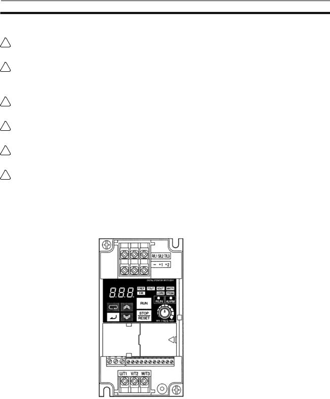
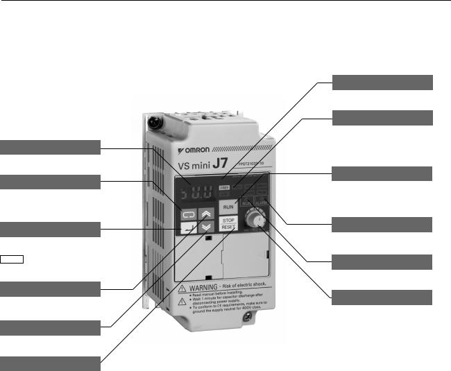
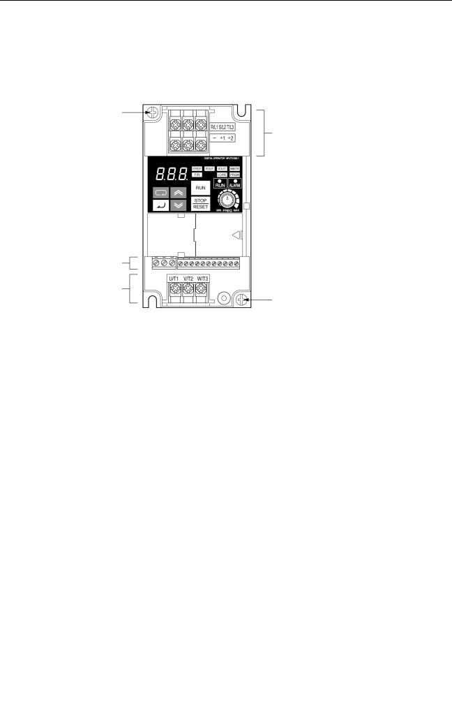
1-2 Nomenclature
Panel
Data display
Display selection key
Switch functions among function display LEDs.
Enter key
Enter data when setting constants. After selecting constant no. at PRGM mode, data are displayed.
Increment key
Increase constant no. or data.
Decrement key
Decrease constant no. or data.
Stop/Reset key
Press to stop the motor. If fault occurs, reset the inverter.
Note
Digital operator
Function display LEDs
Selected function is lit (see the functions below). Its data is displayed on data display.
Operation key
Press to run the motor. The RUN light is ON while running.
Alarm LED
Run LED
Frequency setting volume
Set operational frequency with volume.
1.The front cover functions as a terminal cover. The Digital Operator Unit cannot be removed.
2.Instead of mounting holes, each of the following models has two U-shaped cutouts located diagonally.
CIMR-J7AZ20P1 (0.1 kW), CIMR-J7AZ20P2 (0.25 kW), CIMR-J7AZ20P4 (0.55 kW), and CIMR-J7AZ20P7 (1.1 kW) CIMR-J7AZB0P1 (0.1 kW), CIMR-J7AZB0P2 (0.25 kW), and CIMR-J7AZB0P4 (0.55 kW)
3
Nomenclature |
Chapter 1-2 |
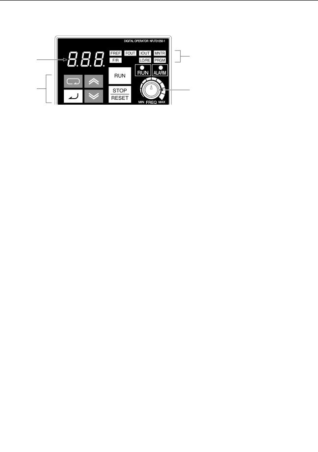
Digital Operator
|
|
Indicators |
Data display |
|
(Setting/Monitor |
|
item indicators) |
|
|
|
|
Keys |
|
FREQ adjuster |
|
|
|
|
|
|
Appearance |
Name |
Function |
|
|
|
|
Data display |
Displays relevant data items, such as frequency reference, output frequency, |
|
|
and parameter set values. |
|
|
|
|
FREQ adjuster |
Sets the frequency reference within a range between 0 Hz and the maximum |
|
|
frequency. |
|
|
|
|
FREF indicator |
The frequency reference can be monitored or set while this indicator is lit. |
|
|
|
|
FOUT indicator |
The output frequency of the Inverter can be monitored while this indicator is lit. |
|
|
|
|
IOUT indicator |
The output current of the Inverter can be monitored while this indicator is lit. |
|
|
|
|
MNTR indicator |
The values set in U01 through U10 are monitored while this indicator is lit. |
|
|
|
|
F/R indicator |
The direction of rotation can be selected while this indicator is lit when |
|
|
operating the Inverter with the RUN Key. |
|
|
|
|
LO/RE indicator |
The operation of the Inverter through the Digital Operator or according to the |
|
|
set parameters is selectable while this indicator is lit. |
|
|
Note This status of this indicator can be only monitored while the Inverter is in |
|
|
operation. Any RUN command input is ignored while this indicator is lit. |
|
|
|
|
PRGM indicator |
The parameters in n01 through n79 can be set or monitored while this |
|
|
indicator is lit. |
|
|
Note While the Inverter is in operation, the parameters can be only monitored |
|
|
and only some parameters can be changed. Any RUN command input |
|
|
is ignored while this indicator is lit. |
|
|
|
|
Mode Key |
Switches the setting and monitor item indicators in sequence. |
|
|
Parameter being set will be canceled if this key is pressed before entering the |
|
|
setting. |
|
|
|
|
Increment Key |
Increases multi-function monitor numbers, parameter numbers, and parameter |
|
|
set values. |
|
|
|
|
Decrement Key |
Decreases multi-function monitor numbers, parameter numbers, and |
|
|
parameter set values. |
|
|
|
|
Enter Key |
Enters multi-function monitor numbers, parameter numbers, and internal data |
|
|
values after they are set or changed. |
|
|
|
|
RUN Key |
Starts the Inverter running when the J7AZ is in operation with the Digital |
|
|
Operator. |
|
|
|
|
STOP/RESET Key |
Stops the Inverter unless parameter n06 is set to disable the STOP Key. |
|
|
Functions as a Reset Key when an Inverter error occurs. (See note.) |
|
|
|
Note For safety reasons, the reset will not work while a RUN command (forward or reverse) is in effect. Wait until the RUN command is OFF before resetting the Inverter.
4
|
|
|
CHAPTER 2 |
|
|
|
Design |
2-1 |
Installation . . . . . . . . . . . . . . . . . . . . . . . . . . . . . . . . . . . . . . . . . . . . . . . . . . . . |
6 |
|
|
2-1-1 |
Dimensions . . . . . . . . . . . . . . . . . . . . . . . . . . . . . . . . . . . . . . . . . . . . |
6 |
|
2-1-2 |
Installations Conditions. . . . . . . . . . . . . . . . . . . . . . . . . . . . . . . . . . . |
8 |
2-2 |
Wiring . |
. . . . . . . . . . . . . . . . . . . . . . . . . . . . . . . . . . . . . . . . . . . . . . . . . . . . . . |
10 |
|
2-2-1 Removing and Mounting the Covers . . . . . . . . . . . . . . . . . . . . . . . . |
11 |
|
|
2-2-2 |
Terminal Block . . . . . . . . . . . . . . . . . . . . . . . . . . . . . . . . . . . . . . . . . |
12 |
|
2-2-3 |
Standard Connections . . . . . . . . . . . . . . . . . . . . . . . . . . . . . . . . . . . . |
16 |
|
2-2-4 Wiring around the Main Circuit . . . . . . . . . . . . . . . . . . . . . . . . . . . . |
17 |
|
|
2-2-5 Wiring Control Circuit Terminals . . . . . . . . . . . . . . . . . . . . . . . . . . . |
27 |
|
|
2-2-6 Conforming to EC Directive . . . . . . . . . . . . . . . . . . . . . . . . . . . . . . . |
29 |
|
5
Installation |
Chapter 2-1 |
2-1 Installation
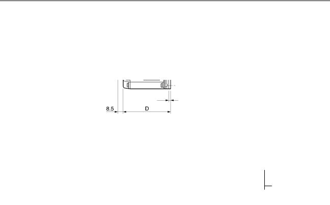
2-1-1 Dimensions
CIMR-J7AZ20P1 to CIMR-J7AZ20P7 (0.1 to 0.75 kW) 3-phase 200-V AC Input CIMR-J7AZB0P1 to CIMR-J7AZB0P4 (0.1 to 0.4 kW) Single-phase 200-V AC Input
118 |
|
128 |
5 |
t |
D1
6 |
56 |
8.5 |
D |
68
Rated voltage |
Model CIMR-J7AZ- |
Dimensions (mm) |
|
Weight (kg) |
|||
|
|
|
|
|
|
|
|
|
|
D |
|
D1 |
|
t |
|
|
|
|
|
|
|
|
|
3-phase 200 V AC |
20P1 |
70 |
10 |
|
3 |
|
Approx. 0.5 |
|
|
|
|
|
|
|
|
|
20P2 |
70 |
10 |
|
3 |
|
Approx. 0.5 |
|
|
|
|
|
|
|
|
|
20P4 |
102 |
42 |
|
5 |
|
Approx. 0.8 |
|
|
|
|
|
|
|
|
|
20P7 |
122 |
62 |
|
5 |
|
Approx. 0.9 |
|
|
|
|
|
|
|
|
Single-phase 200 V AC |
B0P1 |
70 |
10 |
|
3 |
|
Approx. 0.5 |
|
|
|
|
|
|
|
|
|
B0P2 |
70 |
10 |
|
3 |
|
Approx. 0.5 |
|
|
|
|
|
|
|
|
|
B0P4 |
112 |
42 |
|
5 |
|
Approx. 0.9 |
|
|
|
|
|
|
|
|
6
Installation |
Chapter 2-1 |
CIMR-J7AZ21P5 to CIMR-J7AZ22P2 (1.5 to 2.2 kW) 3-phase 200-V AC Input CIMR-J7AZB0P7 to CIMR-J7AZB1P5 (0.75 to 1.5 kW) Single-phase 200-V AC Input CIMR-J7AZ40P2 to CIMR-J7AZ42P2 (0.2 to 2.2 kW) 3-phase 400-V AC Input
Two, 5-dia. holes
118 |
|
128 |
|
|
|
|
|
|
|
|
|
|
|
|
|
|
|
|
|
|
|
|
|
|
|
|
|
|
|
5 |
|
|
|
|
|
|
|
|
5 |
|
|
|
|
|
|
|
|
|
|
|
D1 |
|
|
6 |
|
96 |
|
|
8.5 |
|
|
||||
|
|
|
|
|
|
|
|
|
|||
|
|
|
|
|
|
|
|
|
|
|
|
|
|
|
|
|
|
|
D |
||||
|
|
108 |
|
||||||||
|
|
|
|
|
|
|
|
|
|
|
|
Rated voltage |
Model CIMR-J7AZ- |
Dimensions (mm) |
Weight (kg) |
|
|
|
|
|
|
|
|
D |
D1 |
|
|
|
|
|
|
3-phase 200 V AC |
21P5 |
129 |
64 |
Approx. 1.3 |
|
|
|
|
|
|
22P5 |
154 |
64 |
Approx. 1.5 |
|
|
|
|
|
Single-phase 200 V AC |
B0P7 |
129 |
64 |
Approx. 1.5 |
|
|
|
|
|
|
B1P5 |
154 |
64 |
Approx. 1.5 |
|
|
|
|
|
3-phase 400 V AC |
40P2 |
81 |
16 |
Approx. 1.0 |
|
|
|
|
|
|
40P4 |
99 |
34 |
Approx. 1.1 |
|
|
|
|
|
|
40P7 |
129 |
64 |
Approx. 1.5 |
|
|
|
|
|
|
41P5 |
154 |
64 |
Approx. 1.5 |
|
|
|
|
|
|
42P2 |
154 |
64 |
Approx. 1.5 |
|
|
|
|
|
7
Installation |
Chapter 2-1 |
CIMR-J7AZ24P0 (4.0 kW) 3-phase 200-V AC Input
CIMR-J7AZ44P0 (4.0 kW) 3-phase 400-V AC Input
Two, 5-dia. holes
118 |
128 |
5 |
|
|
|
|
|
5 |
|
6 |
128 |
|
8.5 |
|
D |
D1 |
|
|
|
|
|
||||
|
140 |
|
|
|
|
|
|
|
|
|
|
|
|
|
|
Rated voltage |
Model CIMR-J7AZ- |
Dimensions (mm) |
Weight (kg) |
||||
|
|
|
|
|
|
|
|
|
|
D |
|
D1 |
|
|
|
|
|
|
|
|
|
|
|
3-phase 200 V AC |
24P0 |
161 |
|
71 |
Approx. 2.1 |
||
|
|
|
|
|
|
|
|
3-phase 400 V AC |
44P0 |
161 |
|
71 |
Approx. 2.1 |
||
|
|
|
|
|
|
|
|
2-1-2 Installations Conditions
Provide an appropriate stopping device on the machine side to secure safety. ! WARNING (A holding brake is not a stopping device for securing safety.) Not doing so
may result in injury.
!WARNING
!Caution
Provide an external emergency stopping device that allows an instantaneous stop of operation and power interruption. Not doing so may result in injury.
Be sure to install the product in the correct direction and provide specified clearances between the Inverter and control panel or with other devices. Not doing so may result in fire or malfunction.
!Caution
!Caution
Do not allow foreign objects to enter inside the product. Doing so may result in fire or malfunction.
Do not apply any strong impact. Doing so may result in damage to the product or malfunction.
8
Installation |
Chapter 2-1 |
Installation Direction and Dimensions
Install the Inverter under the following conditions.
• Ambient temperature for operation (panel-mounting): -10°C to 50°C
• Humidity: 95% or less (no condensation)
|
Install the Inverter in a clean location free from oil mist and dust. Alternatively, |
|
install it in a totally enclosed panel that is completely protected from floating |
|
dust. |
|
When installing or operating the Inverter, always take special care so that |
|
metal powder, oil, water, or other foreign matter does not get into the Inverter. |
|
Do not install the Inverter on inflammable material such as wood. |
Direction |
Install the Inverter on a vertical surface so that the characters on the |
|
nameplate are oriented upward. |
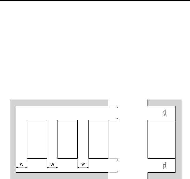
Dimensions |
When installing the Inverter, always provide the following clearances to allow |
|
normal heat dissipation from the Inverter. |
W = 30 mm min. |
100 mm min. |
Air |
Inverter |
Inverter |
Inverter |
Side |
W |
|
W |
|
W |
100 mm min. |
Air |
Ambient Temperature Control
To enhance operation reliability, the Inverter should be installed in an environment free from extreme temperature changes.
If the Inverter is installed in an enclosed environment such as a box, use a cooling fan or air conditioner to maintain the internal air temperature below 50°C. The life of the built-in electrolytic capacitors of the Inverter is prolonged by maintaining the internal air temperature as low as possible.
The surface temperature of the Inverter may rise approximately 30°C higher than the ambient temperature. Be sure to keep away equipment and wires from the Inverter as far as possible if the equipment and wires are easily influenced by heat.
Protecting Inverter from Foreign Matter during Installation
Place a cover over the Inverter during installation to shield it from metal power produced by drilling. Upon completion of installation, always remove the cover from the Inverter. Otherwise, ventilation will be affected, causing the Inverter to overheat.
9

Wiring |
Chapter 2-2 |
2-2 Wiring
!WARNING
!WARNING
!WARNING
!WARNING
!Caution
!Caution
!Caution
!Caution
!Caution
!Caution
Wiring must be performed only after confirming that the power supply has been turned OFF. Not doing so may result in electrical shock.
Wiring must be performed by authorized personnel. Not doing so may result in electrical shock or fire.
Be sure to confirm operation only after wiring the emergency stop circuit. Not doing so may result in injury.
Always connect the ground terminals to a ground of 100 Ω or less for the 200V AC class, or 10 Ω or less for the 400V AC class. Not connecting to a proper ground may result in electrical shock.
Install external breakers and take other safety measures against shortcircuiting in external wiring. Not doing so may result in fire.
Confirm that the rated input voltage of the Inverter is the same as the AC power supply voltage. An incorrect power supply may result in fire, injury, or malfunction.
Connect the Braking Resistor and Braking Resistor Unit as specified in the manual. Not doing so may result in fire.
Be sure to wire correctly and securely. Not doing so may result in injury or damage to the product.
Be sure to firmly tighten the screws on the terminal block. Not doing so may result in fire, injury, or damage to the product.
Do not connect an AC power to the U, V, or W output. Doing so may result in damage to the product or malfunction.
10

Wiring |
Chapter 2-2 |
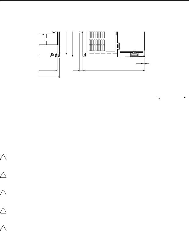
2-2-1 Removing and Mounting the Covers
It is necessary to remove the front cover, optional cover, top protection cover, and thebottom protection cover from the Inverter to wire the terminal block. Follow the instructions below to remove the covers from the Inverter. To mount the covers, take the opposite steps.
Removing the Front Cover
• Loosen the front cover mounting screws with a screwdriver.
• Press the left and right sides of the front cover in the arrow 1 directions and lift the bottom of the cover in the arrow 2 direction to remove the front cover as shown in the following illustration.
1 2
Removing the Top and Bottom Protection Covers and Optional Cover
Removing the Top and Bottom Protection Covers
•After removing the front cover, pull the top and bottom protection covers in the arrow 1 directions.
Removing the Optional Cover
•After removing the front cover, lift the optional cover in the arrow 2 direction based on position A as a fulcrum.
1
Positon A
2
1
11
Wiring |
Chapter 2-2 |
2-2-2 Terminal Block
Before wiring the terminal block, be sure to remove the front cover, top protection cover, and the bottom protection cover.
Position of Terminal Block
Ground terminal
Main circuit input terminals
Control circuit terminals
Main circuit output terminals
Ground terminal
Arrangement of Control Circuit Terminals
Arrangement of Main Circuit Terminals
•CIMR-J7AZ20P1 to CIMR-J7AZ20P7 CIMR-J7AZB0P1 to CIMR-J7AZB0P4
•CIMR-J7AZ21P5 to CIMR-J7AZ24P0 CIMR-J7AZB0P7 to CIMR-J7AZB4P0 CIMR-J7AZ40P2 to CIMR-J7AZ44P0
Main Circuit Input Terminals |
Main Circuit Input Terminals |
(Upper Side) |
(Upper Side) |
Main Circuit Output Terminals |
Main Circuit Output Terminals |
(Lower Side) |
(Lower Side) |
12

Wiring |
|
Chapter 2-2 |
|||
Main Circuit Terminals |
|
||||
|
|
|
|
|
|
|
Symbol |
Name |
Description |
||
|
|
|
|
|
|
R/L1 |
Power Supply input terminals |
CIMR-J7AZ2_: 3-phase 200 to 230 V AC |
|||
|
|
|
|
CIMR-J7AZB_: Single-phase 200 to 240 V AC |
|
S/L2 |
|
||||
|
CIMR-J7AZ4_: 3-phase 380 to 460 V AC |
||||
|
|
|
|
||
|
|
|
|
Note Connect single-phase input to terminals R/L1 and S/L2. |
|
T/L3 |
|
||||
|
|
|
|
|
|
U/T1 |
Motor output terminals |
3-phase power supply output for driving motors. |
|||
|
|
|
|
CIMR-J7AZ2_: 3-phase 200 to 230 V AC |
|
V/T2 |
|
||||
|
CIMR-J7AZB_: 3-phase 200 to 240 V AC |
||||
|
|
|
|
||
|
|
|
|
CIMR-J7AZ4_: 3-phase 380 to 460 V AC |
|
W/T3 |
|
||||
|
|
|
|
|
|
+1 |
|
Connection terminals +1 and +2: |
Connect the DC reactor for suppressing harmonics to terminals |
||
|
|
|
DC reactor connection terminals |
+1 and +2. |
|
+2 |
|
+1 and –: |
When driving the Inverter with DC power, input the DC power to |
||
|
|
|
|||
|
|
|
DC power supply input terminals |
terminals +1 and –. |
|
– |
|||||
|
(Terminal +1 is a positive terminal.) |
||||
|
|
|
|
||
|
|
|
|
|
|
|
|
|
Ground terminal |
Be sure to ground the terminal under the following conditions. |
|
|
|
|
|
CIMR-J7AZ2_: Ground at a resistance of 100 Ω or less. |
|
|
|
|
|
||
|
|
|
|
||
|
|
|
|
CIMR-J7AZB_: Ground at a resistance of 100 Ω or less. |
|
|
|
|
|
CIMR-J7AZ4_: Ground at a resistance of 10 Ω or less, and connect |
|
|
|
|
|
to the power supply’s neutral phase to conform to EC Directives. |
|
|
|
|
|
Note Be sure to connect the ground terminal directly to the |
|
|
|
|
|
motor frame ground. |
|
|
|
|
|
|
|
Note The maximum output voltage corresponds to the power supply input voltage of the Inverter.
13

Wiring |
|
|
|
Chapter 2-2 |
Control Circuit Terminals |
|
|
||
|
|
|
|
|
Symbol |
Name |
Function |
Signal level |
|
|
|
|
|
|
Input |
S1 |
Forward/Stop |
Forward at ON. Stops at OFF. |
Photocoupler |
|
|
|
|
8 mA at 24 V DC |
|
|
|
|
Note NPN is the default setting |
|
S2 |
Multi-function input 1 (S2) |
Set by parameter n36 |
|
|
|
|
(Reverse/Stop) |
for theses terminals. Wire |
|
|
|
|
them by providing a com- |
|
S3 |
Multi-function input 2 (S3) |
Set by parameter n37 |
|
|
mon ground. No external |
|||
|
|
|
(Fault reset) |
power supply is required. To |
|
|
|
|
provide an external power |
|
S4 |
Multi-function input 3 (S4) |
Set by parameter n38 |
|
|
supply and wire the termi- |
|||
|
|
|
(External fault:Normally open) |
|
|
|
|
nals through a common |
|
|
|
|
|
|
|
S5 |
Multi-function input 4 (S5) |
Set by paramter n39 |
|
|
positive line, however, set |
|||
|
|
|
(Multi-step reference 1) |
the SW7 to PNP and make |
|
|
|
|
sure that the power supply |
|
SC |
Sequence input common |
Common for S1 through S5 |
|
|
is at 24 V DC ±10%. |
|||
|
|
|
|
|
|
|
|
|
|
|
FS |
Frequency reference |
DC power supply for frequency |
20 mA at 12 V DC |
|
|
power supply |
reference use |
|
|
|
|
|
|
|
FR |
Frequency reference input |
Input terminal for frequency |
0 to 10 V DC |
|
|
|
reference use |
(input impedance: 20 kΩ) |
|
|
|
|
|
|
FC |
Frequency reference common |
Common for frequency |
|
|
|
|
reference use |
|
|
|
|
|
|
Output |
MA |
Multi-function contact output |
Set by parameter n40 |
Relay output |
|
|
(Normally open) |
(during running) |
1 A max. at 30 V DC |
|
|
|
|
1 A max. at 250 V AC |
|
MB |
Multi-function contact output |
|
|
|
|
|
||
|
|
(Normally closed) |
|
|
|
|
|
|
|
|
MC |
Multi-function contact output |
Common for MA and MB use |
|
|
|
common |
|
|
|
|
|
|
|
|
AM |
Analog monitor output |
Set by parameter n44 |
2 mA max. at 0 to 10 V DC |
|
|
|
(Output frequency) |
|
|
|
|
|
|
|
AC |
Analog monitor output |
Common for AM use |
|
|
|
common |
|
|
|
|
|
|
|
Note 1. Depending on the parameter settings, various functions can be selected for multi-function inputs and multi-function contacts outputs.
2. Functions in parentheses are default settings.
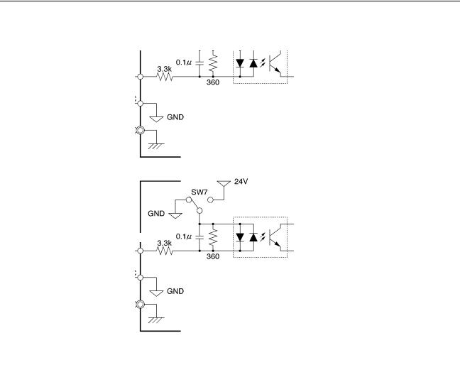
Selecting Input Method
Switches SW7 and SW8, both of which are located above the control circuit terminals, are used for input method selection.Remove the front cover and optional cover to use these switches.
SW7 SW8
SW7 |
|
SW8 |
Selector |
|
|
|
|
Control circuit terminal block
14
|
Wiring |
|
|
|
|
|
|
|
|
|
|
|
|
|
|
|
|
|
|
|
Chapter 2-2 |
Selecting Frequency |
By using SW7, NPN or PNP input can be selected as shown below. |
||||||||||||||||||||
Reference Input Method |
|
|
|
|
|
|
|
|
|
|
|
|
|
|
|
|
|
|
|
|
|
|
|
|
|
|
|
|
|
|
|
|
|
|
|
|
|
|
|
|
|
24V |
|
|
|
|
NPN |
|
|
|
|
|
|||||||||||||
|
|
|
|
|
|
|
|
|
|
|
|
|
|
|
|
|
|
|
|
|
|
|
|
|
|
|
|
|
|
|
|
|
|
|
|
SW7 |
|
|
|
|
|||
|
|
|
|
|
|
|
|
|
|
|
|
|
|
|
|
|
|
||||
|
|
|
|
|
|
|
|
|
|
|
|
|
|
|
|
|
|
|
|||
|
|
|
|
|
|
|
|
|
|
|
|
|
|
|
|
|
|
|
|
|
|
|
|
|
|
|
|
|
|
|
GND |
|
|
|
|
|
|
|
|
|
|
|
|
|
|
|
|
|
|
|
|
|
|
|
|
|
|
|
|
|
|
||||
|
|
|
|
|
S1 to55 |
|
|
|
|
|
0.1 |
|
|
|
|||||||
|
|
|
|
|
3.3k |
|
|
|
|
|
|
||||||||||
|
|
|
|
|
|
|
|
|
|
|
|
|
|
|
|
|
|
|
|||
|
|
|
|
|
|
|
|
|
|
|
|
|
|
|
|
||||||
|
|
|
|
|
|
|
|
|
360 |
|
|
|
|||||||||
|
|
|
|
|
|
|
|
|
|
|
|
|
|
|
|
|
|
|
|
|
|
|
|
|
|
|
|
SC |
|
|
|
|
|
|
|
|
|
|
|
|
|
|
|
|
|
|
|
|
|
|
|
|
|
|
|
|
|
|
|||||||
|
|
|
|
|
|
|
|
|
|
|
|
GND |
|||||||||
24V
PNP |
|
|
|
|
|
|
|
|
|
||||||
|
|
|
|
|
SW7 |
|
|||||||||
|
|
|
|
|
|
|
|
|
|
|
|
|
|||
|
|
|
|
|
|
|
|
|
|
|
|
|
|
|
|
|
|
|
|
|
|
|
GND |
|
|
|
|
|
|
|
|
|
|
|
|
|
|
|
|
|
|
|
|
||||
|
|
|
|
|
|
|
0.1 |
|
|||||||
|
|
|
S1 to55 |
|
|
|
|
|
|
|
|||||
|
3.3k |
|
|||||||||||||
|
|
|
|||||||||||||
|
|
|
|
|
|
|
|
|
|
|
|
|
|
||
|
|
|
|
|
|
|
|
|
|
|
|
|
|
||
|
|
|
|
|
|
|
|
|
|
|
|||||
|
24VVDCDC |
|
|
|
|
|
|
|
|
||||||
360 |
|||||||||||||||
|
(+10%) |
|
|
|
|
|
|
|
|
|
|
|
|
|
|
|
|
|
|
SC |
|
|
|
|
|
|
|
|
|
|
|
|
|
|
|
|
|
|
|
|
|
|
|
|
|
|
|
|
|
|
|
|
|
|
|
|
|
|
|
|
|
|
|
|
|
|
|
|
|
|
|
|
GND |
|
|||||
Selecting Frequency
Reference Input Method
By using SW8, frequency reference voltage or current input can be selected. Parameter settings are required together with the selection of the frequency reference input method.
Frequency |
SW8 setting |
Frequency |
reference input |
|
reference selection |
method |
|
(parameter n03) |
|
|
|
Voltage input |
V (OFF) |
Set value 2 |
|
|
|
Current input |
I (ON) |
Set value 3 or 4 |
|
|
|
15
Wiring |
Chapter 2-2 |
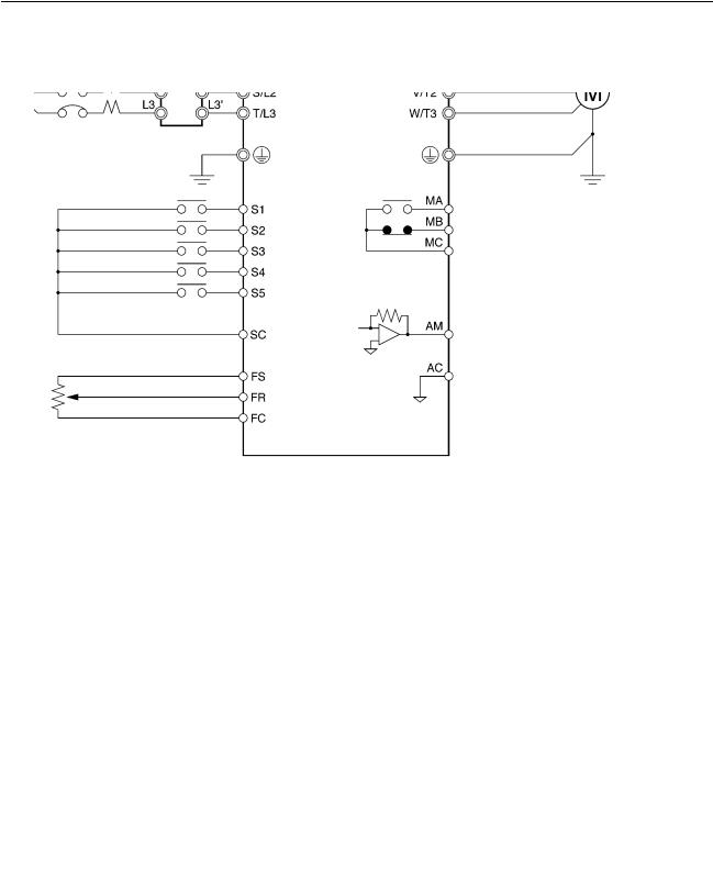
2-2-3 Standard Connections
DC reactor (optional)
Noise Filter
3-phase 200 V AC Single-phase 200 V AC (see note 1)
3-phase 400 V AC
|
Forward/Stop |
|
Multi-function input 1 (S2) |
|
Multi-function input 2 (S3) |
|
Multi-function input 3 (S4) |
|
Multi-function input 4 (S5) |
|
Sequence input common |
|
Frequency reference power |
|
supply 20 mA at +12 V |
FREQ |
Frequency reference input |
adjuster |
Frequency reference common |
|
(2kΩ, 1/4 W min.)
Multi-function contact output NO
NC
Common
Analog monitor output
Analog monitor output common
Note 1. Connect single-phase 200 V AC to terminals R/L1 and S/L2 of the CIMRJ7AZB_.
2.The braking resistor cannot be connected because no braking transistor is incorporated.
Example of 3-wire Sequence Connections
Stop switch (NC)
RUN switch (NO)
RUN input (Operates with the stop switch and RUN switch closed.)
Stop input (Stops with the stop switch opened.)
Direction switch
Forward/Stop reference (Forward with the direction switch opened and reverse with the direction switch closed.)
Sequence input common
Note Set parameter n37 for 3-wire sequence input.
16
 Loading...