

Olson Technology OT-1000-HH User Manual Rev.X2
Model OT-1000-HH
1GHz SuperMod Optical Transmitter, DWDM
ADVANCED OPERATING MANUAL
The features mentioned in this Advanced OT-1000-HH Manual can be accessed only with
the optional OT-NEC-A, Network Element Controller.
24926 Highway 108
Sierra Village, CA 95346
Phone: (800) 545-1022
Fax: (209 586-1022
025-010573 Rev. X2 E-Mail: sales@olsontech.com
11/12/09

TABLE OF CONTENTS
CONTROLLING THE OT-1000-HH VIA NEC ........................................................................... 4
Figure 1 — Display of Web Browser (Microsoft Internet Explorer) 4
STATUS MENU..........................................................................................................................................................5
Figure 2 — Status Menu 5
PARAMETER MENU.................................................................................................................................................6
Figure 3 — Parameter Menu 6
VOLTAGES MENU ....................................................................................................................................................7
Figure 4 — Voltages Menu 7
SETTINGS MENU......................................................................................................................................................8
Figure 5 — Settings Menu 8
Adjusting the Optical Output Power........................................................................................................................9
Figure 6 — Changing the Optical Output Power 9
Switching Optical Output Power On/Off ...............................................................................................................10
Figure 7 — Switching Optical Output Power On/Off 10
Changing the ITU Frequency ...............................................................................................................................11
Figure 8 — Changing the ITU Frequency 11
Selecting the AGC Mode......................................................................................................................................12
Figure 9 — Selecting the AGC Mode 12
Setting the RF Gain (AGC-Off Mode only)...........................................................................................................13
Figure 10 — Setting the RF Gain 13
Figure 11 — Setting the RF Gain: Value out of Range 13
Setting the RF Mode.............................................................................................................................................14
Figure 12 — Setting the RF Mode 14
Setting the RF Gain Slope....................................................................................................................................15
Figure 13 — Setting the RF Gain Slope 15
Setting the OMI of the Pilot Tone .........................................................................................................................16
Figure 14 — Setting the OMI of the Pilot Tone 16
Setting the Pilot Tone Frequency.........................................................................................................................17
Figure 15 — Setting the Pilot Tone Frequency 17
Setting OMI
Figure 16 — Setting of OMI
Line Coding...........................................................................................................................................................19
(AGC-On Mode only).................................................................................................................18
totrms
18
totrms
Figure 17 — Turning Line Coding On/Off 19
Figure 18 — Setting the Linecode Number 19
Setting the RF Gain Limit (AGC-On Mode only) ..................................................................................................20
Figure 19 — Setting Maximum RF Gain 20
Figure 20 — Setting Maximum RF Gain: Value out of range 20
LIMITS MENUS........................................................................................................................................................21
Figure 21 — Limits 1 Menu 21
EVENT MASK MENU ..............................................................................................................................................22
Figure 22 — Setting the Event Mask 22
025-010573 Rev. X2 - 2 - www.olsontech.com

PROPERTIES MENU...............................................................................................................................................23
Figure 23 — Properties Menu of OT-1000-HH 23
SOFTWARE UPDATE.............................................................................................................................................24
Figure 24 — Devices Update Screen 24
ORDERING INFORMATION....................................................................................................................................24
025-010573 Rev. X2 - 3 - www.olsontech.com
CONTROLLING THE OT-1000-HH VIA NEC
The RS-485 interface is used to manage the OT-1000-HH, such as reading data and changing settings. It
is recommended to connect this interface to a network element controller like:
The Olson network element controller OT-NEC-A allows supervising and controlling the function of the
transmitter and other equipment connected to the RS485 master interface, using the integrated Ethernet
webserver (HTTP) interface.
In order to enable the communication with a NEC, the RS485 slave port of the OT-1000-HH has to be
connected with the RS485 master port of the OT-NEC-A as shown in the figure below. In general, this is
accomplished by the sub-rack bus wiring. The NEC Ethernet interface has to be connected to a PC either
directly via a crossed Ethernet cable or via a LAN. It is important to set the IP address of the NEC in order to be compatible with the available LAN IP addresses. The IP address can be changed using the
push-buttons and the LCD (please refer to NEC operating manual). In the example below the IP address
has been set to be 172.23.41.65.
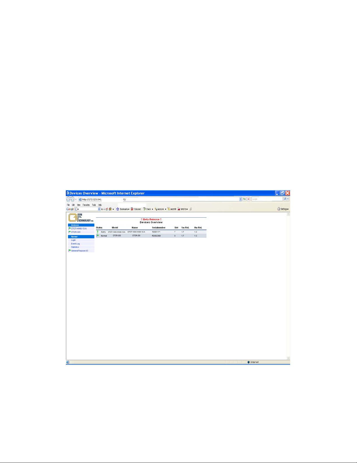
Starting from OT-NEC-A application software release 1.12 or higher, a picture as shown below will appear on the web screen when a web browser communicates with the NEC:
Figure 1 — Display of Web Browser (Microsoft Internet Explorer)
In “Devices” all devices are shown which are connected to and recognized by the NEC. In the devices-column user, defined aliasnames for the OT-1000-HH are shown. In the “Devices” overview window the states, models, alias name, serial number, software and hardware releases are shown. By performing a mouse-click on one of the devices in the devices column, a device specific menu will open as
shown below.
025-010573 Rev. X2 - 4 - www.olsontech.com
For details on operating the OT-1000-HH via a NEC, please refer to the NEC operating manual.
STATUS MENU
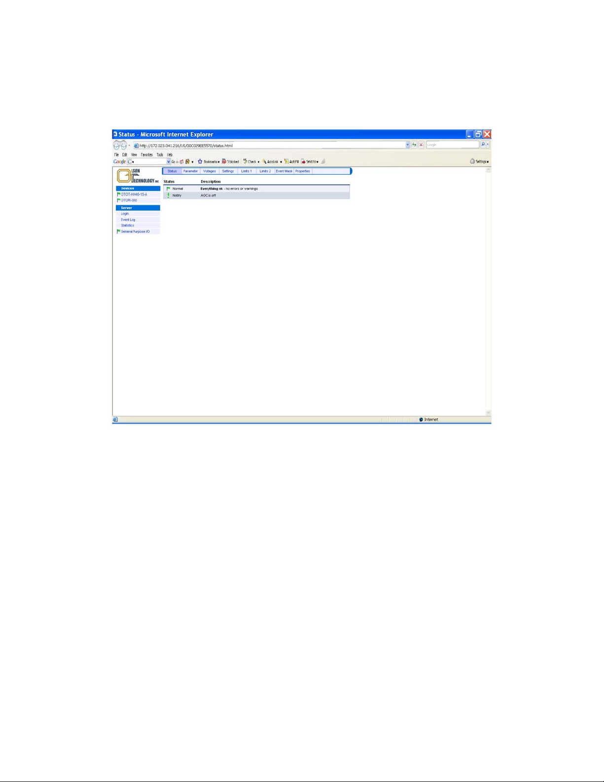
The picture below shows the status menu of the OT-1000-HH.
Figure 2 — Status Menu
The actual status of the transmitter is shown using a mark and a description. There are several marks,
filled or unfilled, used to show all events.
A green flag indicates that the transmitter is working properly.
An orange (yellow) flag shows a warning. A certain parameter is out of the nominal range.
The unit should be checked and the problem resolved as soon as possible.
Red flags indicate urgent alarms. An immediate action is required to fix the failure.
An exclamation mark provides a message about a certain mode of operation or change
025-010573 Rev. X2 - 5 - www.olsontech.com
PARAMETER MENU
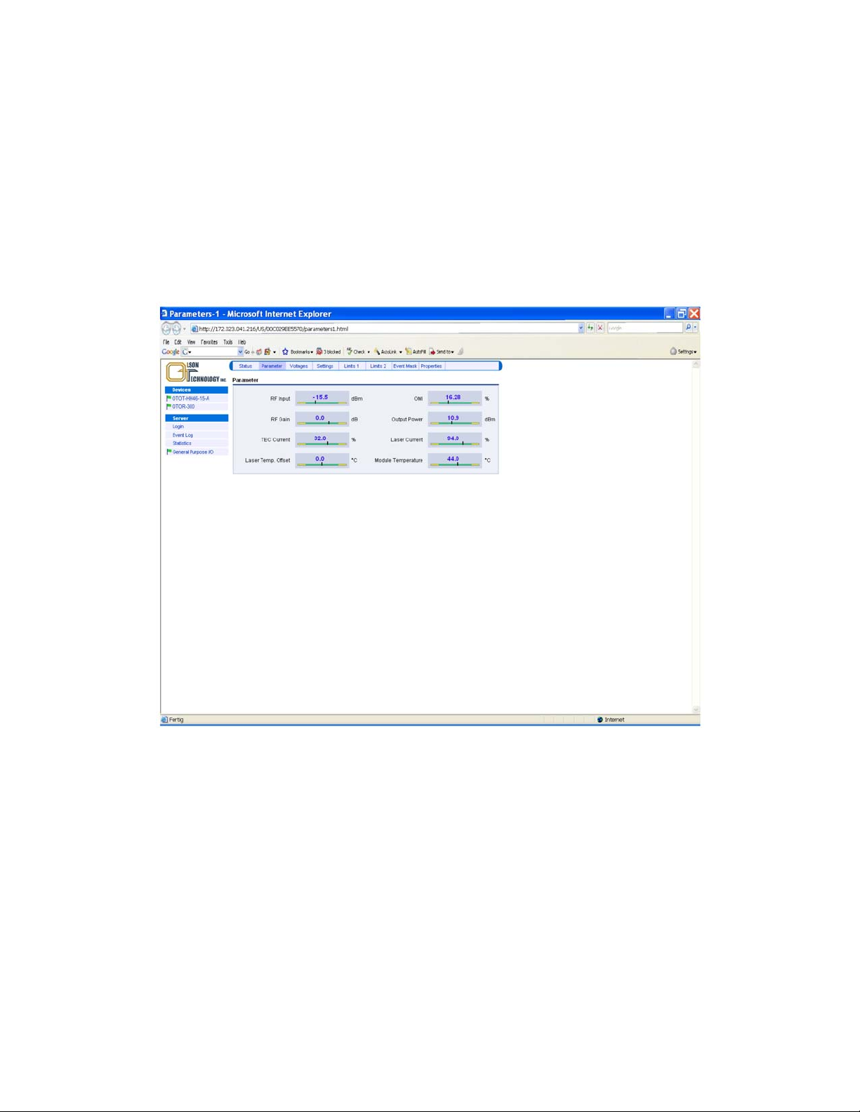
The parameters menu displays the most important operation values of the transmitter:
RF input power (root-mean-square value)
Optical modulation index (total root-mean-square value)
RF Gain
Optical output power
Thermo electric cooler TEC current
Laser bias current
Laser temperature (offset to 25°C)
Transmitter module temperature
Figure 3 — Parameter Menu
For a proper operation, the black vertical bars should meet the green fields.
Note: The scaling of the green and yellow fields might be different in order to obtain a good reading, es-
pecially of the green field.
025-010573 Rev. X2 - 6 - www.olsontech.com
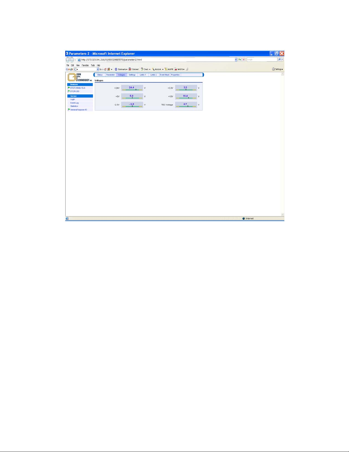
VOLTAGES MENU
The voltages menu displays all internal supply voltages like shown below:
Figure 4 — Voltages Menu
For a proper operation, the black vertical bars should meet the green fields.
Note: The thresholds for alarms are not user adjustable but by factory setting only.
025-010573 Rev. X2 - 7 - www.olsontech.com
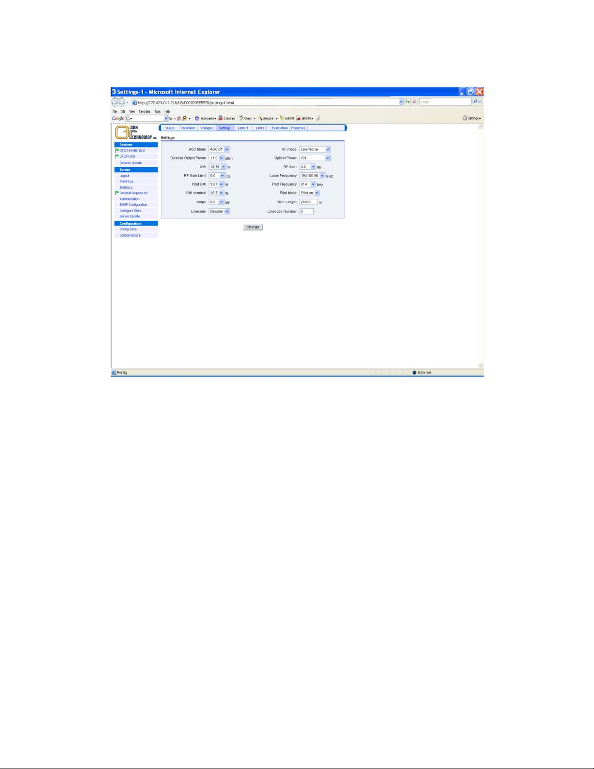
SETTINGS MENU
This menu allows changing some basic transmitter adjustments.
Figure 5 — Settings Menu
025-010573 Rev. X2 - 8 - www.olsontech.com
 Loading...