

Page 1
025-000564 Rev X7
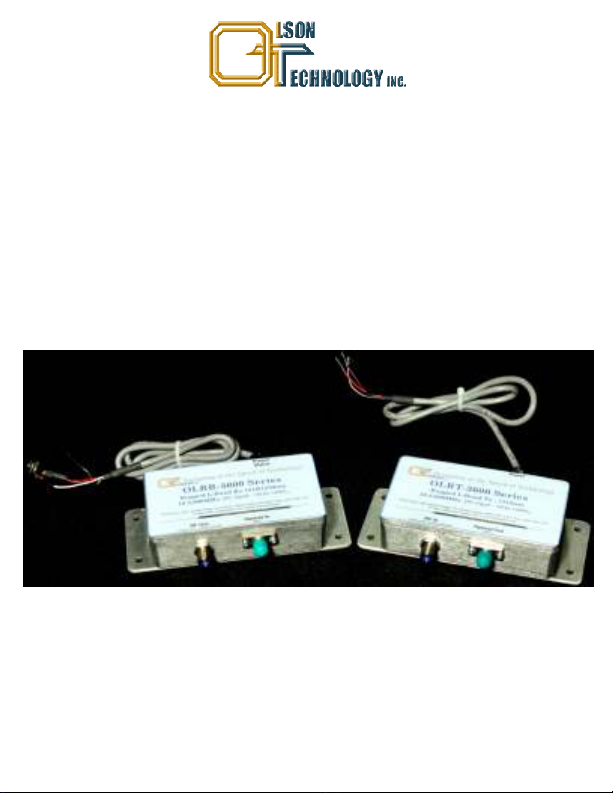
OLRT / OLRR-3000
Rugged L-Band Fiber Optic Link
500 - 3,000MHz
10 - 3,600MHz
INSTRUCTION MANUAL
Phone: (209) 586-1022
(800) 545-1022
Fax: (209) 586-1026
E-Mail: salessupport@olsontech.com
www.olsontech.com
Page 1
09/04/12
Page 2

SAFETY WARNINGS
LASER RADIATION
The OLRT laser transmitter emits invisible radiation that can cause permanent eye
damage. AVOID DIRECT EXPOSURE TO BEAM. Operate the transmitter only with the
proper optical fiber installed in the transmitter optical connector. Power to the OLRT
transmitter should be turned-off or preferably, disconnected whenever the optical
connector cover is opened and there is no installed fiber (as when the fiber connector is
being installed or removed from the transmitter connector).
NEVER USE ANY OPTICAL INSTRUMENT TO VIEW THE OUTPUT OF THE
LASER TRANSMITTER. “OPTICAL INSTRUMENT” INCLUDES MAGNIFYING
GLASSES, ETC.
NEVER LOOK INTO THE OUTPUT OF THE LASER TRANSMITTER
NEVER LOOK INTO THE OUTPUT OF A FIBER CONNECTED TO A LASER
TRANSMITTER.
NEVER LOOK INTO OR USE ANY OPTICAL INSTRUMENT TO VIEW THE
DISTANT END OF A FIBER THAT MAY BE CONNECTED DIRECTLY OR VIA AN
OPTICAL SPLIT, TO A TRANSMITTER THAT MAY BE OPERATING. THIS
SPECIFICALLY APPLIES TO FIBERS THAT ARE TO BE CONNECTED TO
RECEIVERS (SUCH AS THE OLRR RECEIVER) OR OTHER DEVICES AT ANY
DISTANCE FROM THE LASER TRANSMITTER.
SHOCK HAZARD
The OLRT/OLRR is designed for indoor use only. Direct exposure to moisture must be
avoided.
Page 2
Page 3

GENERAL FEATURES
The OLRT L-Band fiber optic transmitter and the OLRR L-Band fiber optic receiver form
the basic L-Band Fiber Distribution System. The wide bandwidth 500MHz to 3,000MHz
or 10MHz to 3,600MHz allows for a wide variety of communications applications
including L-Band satellite antenna remoting, trunking radio, telemetry tracking and time
and frequency reference distribution. The extended frequency range to 3.6GHz allows
this to accommodate additional transponders including European satellite
communications applications. The enhanced bandwidth also facilitates stacked LNB
applications to accommodate additional transponders containing enhanced DBS
services (HDTV, local channels, etc.) over single-mode fiber for DBS distribution.
These stand-alone versions are designed for mounting in outdoor enclosures or in other
small spaces. For powering, the stand-alone units both the transmitter and receiver can
be powered via the wire leads or on the center of the coax connector.
RF PERFORMANCE
The specifications below are with 10dB link optical loss and >55dB optical return loss.
RF Frequency Range 500-3,000MHz or 10-3,600MHz
Amplitude Flatness (>50MHz) ±1.5dB for any 500MHz
±0.35dB for any 40 MHz
Return Loss 10dB
I/O Connector F-Type Female (75 Ohm) Standard
SMA, BNC (50 Ohm) Optional
Link Gain (High-Gain Receiver) @ 2GHz -4 ± 5 dB
Noise Figure See Table 1
Input 1 dB Compression >-17dBm, see Figure 2
Input IP3 -9.5dBm Typical
Max. Total RF Power in -14dBm
Page 3
Page 4

Table 1 - NF vs. Rx Power
Figure 1 - P1dB Performance
OPTICAL PERFORMANCE
Optical Fiber S M 9/125µm ( Corning SMF-28 or Equivalent)
Tx/Rx Optical Return Loss >55dB
Tx/Rx Optical Connector FC/APC or SC/APC
Rx Wavelength 1270-1610nm
Rx Optical Input Power (PIN) -15 to +3dBm
Rx Optical Input Power (APD) -22 to -3dBm
Rx Alarm Standalone Optical Input Power Low ( Open Collector Output)
Less than -15dBm (PIN), -22dBm (APD)
Tx Model # -D5 -D4 -C4
Tx Laser Type DFB DFB DFB/CWDM
Tx Output Power 5dBm 4dBm 4dBm
Tx Wavelength 1310 1550 1XX0
PIN Rx Link Optical Budget 2 to 20dB 1 to19dB 1 to 19dB
APD Rx Link Optical Budget 9 to 27dB 8 to 26dB 8 to 26dB
XX= 47, 49, 51, 53, 55, 57, 59, 61 ITU-grid CWDM wavelengths.
Page 4
Page 5

DC POWERING AND ALARMS
The current requirements for the Tx and Rx units are as follows:
Input Voltage 8VDC 12VDC 15VDC 18VDC 24VDC
Tx 250mA 170mA 135mA 115mA 85mA
Rx 200mA 150mA 120mA 100mA 70mA
CAUTION!
The Tx & Rx have flying leads which carry DC inputs and alarms. Any unused wires
should be wrapped with electrical tape to avoid shorting that could damage the unit.
The Tx & Rx have built in bias-T for remote powering of an LNB for the Tx or could be
used to power the Tx & Rx though the RF connector. This feature can be enabled or
disabled (Factory Preset) by moving the internal jumper JP1, see Figures 2 & 3. The Tx
& Rx is powered by the Red Wire; +8V to +24 V and the Black Wire; ground or “-”. The
DC DC
flying cable also has a shield wire that can be grounded to shield any external signals.
The Rx also has a Brown or White Wire that is an Open Collector Low Optical Level
Alarm. It pulls low when the optical level falls below an acceptable level.
Flying Lead Signal Description:
COLOR Tx/Rx SIGNAL DESCRIPTION
Red Tx DC Input, 8-24 V
DC
Black Tx Ground, DC Return
Silver Tx Shield, Shield wire, connect to Ground
Red Rx DC Input, 8-24 V
DC
Black Rx Ground, DC Return
Silver Rx Shield, Shield wire, connect to Ground
Brown or White Rx Open Collector Output/Low Rcvd Optical Power
INSTALLATION
Optical Connectors
Only APC type connectors in the product. Most installation problems are caused by the
use of the wrong type of mating optical connector. Be sure that all mating optical
connectors are APC type. They are usually green. Mating to a PC or UPC type will result
in poor to no performance. PC or UPC connectors sometimes have a blue marking.
Page 5
Page 6

Figure 2 - Tx JP1 Location
Shunt Shown in the
LNB Power Disabled
Position (Factory Default)
Figure 3 - Rx JP1 Location
Shunt Shown in the
LNB Power Disabled
Position (Factory Default)
Cleaning Optical Connectors
Fiber optic connectors on the cable come pre-terminated should be clean and capped,
so one can usually remove the cap and make the connection without cleaning the
connector, but, if there is any doubt it is good practice to clean the optical connectors
before making the connection. Once the connection is made, there should be no need
clean the connector as long as the connector remains connected.
The fiber ends can be damaged by the insertion of contaminated connectors. Some
types of customer damage to connectors are not covered under warranty. Fiber
connectors should never be left uncovered. Pre-packaged alcohol wipes are a
convenient means of cleaning optical connectors. Clean alcohol and lint free wipes,
such as Kim-Wipe type 34155, or swabs may also be used.
More sophisticated fiber optic connector cleaners, such as the Senko SmartCleaner
(SCK-SC-250) are very effective for cleaning external and internal fiber optic
connectors.
Senko SmartCleaner
Page 6
Page 7

Physical Size
Mount modules to enclosure using #8 screws and split lock washers. Mount the
modules with the RF and Optical connectors mounted down to prevent moisture from
entering. For a watertight seal, pot the optical connectors with RTV. If the enclosure
provides enough water protection you can skip this step. There are no user adjustments
on modules. To optimize Tx RF input, external amplifiers or attenuators may be
required.
* Connect the optical fiber to both the transmitter and receiver. Insure the optical iput
to the receiver is within the specified range.
* Verify the proper RF level out of the LNB and connect the LNB output to the RF input
of the transmitter
* Connect the RF out of the receiver to the distribution amplifier or TV set top receiver
* Apply power to both modules, the system should now be operational as there are no
user adjustments required on the modules (NOTE: Applying power before RF
connections are made, may damage the unit.)
Page 7
Page 8

ORDERING INFORMATION
Tx Model Number
OLRT-D3013-D5-FA 500MHz-3GHz Tx, 1310nm, +5dBm/3mW DFB, 75Ω, FC/APC
OLRT-D3013-D5-50-FA 500MHz-3GHz Tx, 1310nm, +5dBm/3mW DFB, 50Ω, FC/APC
OLRT-D3013-D5-SA 500MHz-3GHz Tx, 1310nm, +5dBm/3mW DFB, 75Ω, SC/APC
OLRT-D3013-D5-50-SA 500MHz-3GHz Tx, 1310nm, +5dBm/3mW DFB, 50Ω, SC/APC
OLRT-D3015-D4-FA 500MHz-3GHz Tx, 1550nm, +4dBm/2.5mW DFB, 75Ω, FC/APC
OLRT-D3015-D4-50-FA 500MHz-3GHz Tx, 1550nm, +4dBm/2.5mW DFB, 50Ω, FC/APC
OLRT-D3015-D4-SA 500MHz-3GHz Tx, 1550nm, +4dBm/2.5mW DFB, 75Ω, SC/APC
OLRT-D3015-D4-50-SA 500MHz-3GHz Tx, 1550nm, +4dBm/2.5mW DFB, 50Ω, SC/APC
OLRT-D30xx-C4-FA 500MHz-3GHz Tx, 1xx0nm, 4dBm/2.5mW CWDM DFB, 75Ω, FC/APC
OLRT-D30xx-C4-50-FA 500MHz-3GHz Tx, 1xx0nm, 4dBm/2.5mW CWDM DFB, 50Ω, FC/APC
OLRT-D30xx-C4-SA 500MHz-3GHz Tx, 1xx0nm, 4dBm/2.5mW CWDM DFB, 75Ω, SC/APC
OLRT-D30xx-C4-50-SA 500MHz-3GHz Tx, 1xx0nm, 4dBm/2.5mW CWDM DFB, 50Ω, SC/APC
OLRT-X3613-D5-FA 10MHz-3.6GHz Tx, 1310nm, +5dBm/3mW DFB, 75Ω, FC/APC
OLRT-X3613-D5-50-FA 10MHz-3.6GHz Tx, 1310nm, +5dBm/3mW DFB, 50Ω, FC/APC
OLRT-X3613-D5-SA 10MHz-3.6GHz Tx, 1310nm, +5dBm/3mW DFB, 75Ω, SC/APC
OLRT-X3613-D5-50-SA 10MHz-3.6GHz Tx, 1310nm, +5dBm/3mW DFB, 50Ω, SC/APC
OLRT-X3615-D4-FA 10MHz-3.6GHz Tx, 1550nm, +4dBm/2.5mW DFB, 75Ω, FC/APC
OLRT-X3615-D4-50-FA 10MHz-3.6GHz Tx, 1550nm, +4dBm/2.5mW DFB, 50Ω, FC/APC
OLRT-X3615-D4-SA 10MHz-3.6GHz Tx, 1550nm, +4dBm/2.5mW DFB, 75Ω, SC/APC
OLRT-X3615-D4-50SA 10MHz-3.6GHz Tx, 1550nm, +4dBm/2.5mW DFB, 50Ω, SC/APC
OLRT-X36xx-C4-FA 10MHz-3.6GHz Tx, 1xx0nm, 4dBm/2.5mW CWDM DFB, 75Ω, FC/APC
OLRT-X36xx-C4-50-FA 10MHz-3.6GHz Tx, 1xx0nm, 4dBm/2.5mW CWDM DFB, 50Ω, FC/APC
OLRT-X36xx-C4-SA 10MHz-3.6GHz Tx,1xx0nm, 4dBm/2.5mW CWDM DFB, 75Ω, SC/APC
OLRT-X36xx-C4-50-SA 10MHz-3.6GHz Tx,1xx0nm, 4dBm/2.5mW CWDM DFB, 50Ω, SC/APC
where xx = 47, 49, 51, 53, 55, 57, 59 or 61
Rx Model Number
OLRR-X3600-HG-FA 10MHz-3.6GHz Rx, PIN Detector, -15 to +3dBm Input, 75Ω, FC/APC
OLRR-D3000-HG-SA 500MHz-3GHz Rx, PIN Detector, -15 to +3dBm Input, 75Ω, SC/APC
OLRR-X3600S-HG-FA 10MHz-3.6GHz Rx, APD Option, -22 to -3dBm Input, 75Ω, FC/APC
OLRR-D3000S-HG-SA 500MHz-3GHz Rx, APD Option, -22 to -3dBm Input, 75Ω, SC/APC
PS Model Number
Model OTPS-12A Power Supply, Universal AC Input, +12 V , 1.5A Output
Model OTPS-18A Power Supply, Universal AC Input, +18 V , 1.0A Output
DC
DC
Page 8
 Loading...