


NTL10850
NordicTrack NTL10850 User Manual
Visit our website at
www.nordictrack.com
new products, prizes,
fitness tips, and much more!
Patent Pending
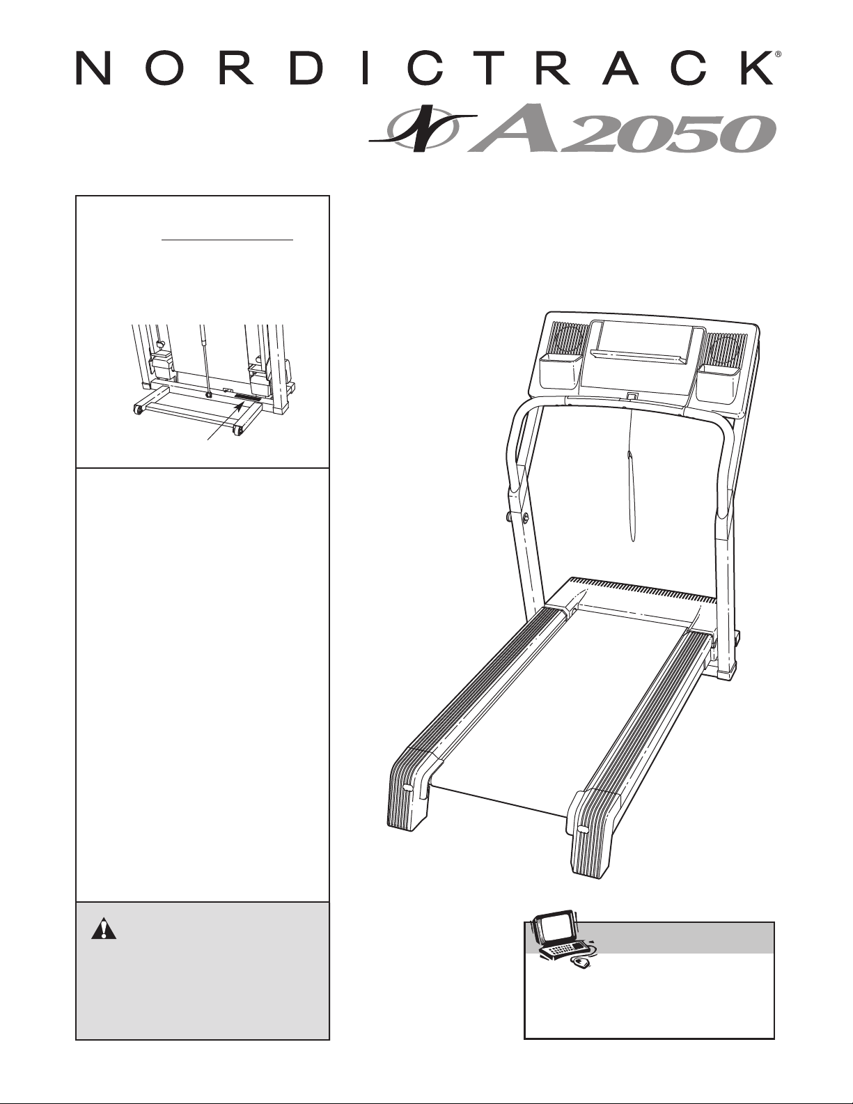
Model No. NTL10850
Serial No.
Find the serial number in the location
shown below. Write the serial number
in the space above for reference.
Serial Number Decal
QUESTIONS?
If you have questions, or if there
are missing parts, we will guarantee complete satisfaction
through direct assistance from
our factory.
USER'S MANUAL
TO AVOID DELAYS, PLEASE
CALL DIRECT TO OUR TOLLFREE CUSTOMER HOT LINE.
The trained technicians on our
Customer Hot Line will provide
immediate assistance, free of
charge to you.
CUSTOMER HOT LINE:
1-888-825-2588
Mon.–Fri., 6 a.m.–6 p.m. MST
CAUTION
Read all precautions and instruc
tions in this manual before using
this equipment. Save this manual
for future reference.
-

TABLE OF CONTENTS
IMPORTANT PRECAUTIONS . . . . . . . . . . . . . . . . . . . . . . . . . . . . . . . . . . . . . . . . . . . . . . . . . . . . . . . . . . . . . . . . .3
BEFORE YOU BEGIN . . . . . . . . . . . . . . . . . . . . . . . . . . . . . . . . . . . . . . . . . . . . . . . . . . . . . . . . . . . . . . . . . . . . . . .5
ASSEMBLY . . . . . . . . . . . . . . . . . . . . . . . . . . . . . . . . . . . . . . . . . . . . . . . . . . . . . . . . . . . . . . . . . . . . . . . . . . . . . . .6
OPERATION AND ADJUSTMENT
HOW TO FOLD AND MOVE THE TREADMILL . . . . . . . . . . . . . . . . . . . . . . . . . . . . . . . . . . . . . . . . . . . . . . . . . .24
TROUBLESHOOTING . . . . . . . . . . . . . . . . . . . . . . . . . . . . . . . . . . . . . . . . . . . . . . . . . . . . . . . . . . . . . . . . . . . . . .26
CONDITIONING GUIDELINES . . . . . . . . . . . . . . . . . . . . . . . . . . . . . . . . . . . . . . . . . . . . . . . . . . . . . . . . . . . . . . .28
PART LIST . . . . . . . . . . . . . . . . . . . . . . . . . . . . . . . . . . . . . . . . . . . . . . . . . . . . . . . . . . . . . . . . . . . . . . . . . . . . . . .30
ORDERING REPLACEMENT PARTS . . . . . . . . . . . . . . . . . . . . . . . . . . . . . . . . . . . . . . . . . . . . . . . . . . . . . . . . . .31
LIMITED WARRANTY . . . . . . . . . . . . . . . . . . . . . . . . . . . . . . . . . . . . . . . . . . . . . . . . . . . . . . . . . . . . . . .Back Cover
Note: An EXPLODED DRAWING is attached in the center of this manual.
. . . . . . . . . . . . . . . . . . . . . . . . . . . . . . . . . . . . . . . . . . . . . . . . . . . . . . . . . . . .10
NordicTrack is a registered trademark of ICON IP, Inc.
2

IMPORTANT PRECAUTIONS
WARNING: To reduce the risk of burns, fire, electric shock, or injury to persons, read the
following important precautions and information before operating the treadmill.
1. It is the responsibility of the owner to ensure
that all users of this treadmill are adequately
informed of all warnings and precautions.
2. Use the treadmill only as described.
3. Place the treadmill on a level surface, with at
least eight feet of clearance behind it and two
feet on each side. Do not place the treadmill
on any surface that blocks air openings. To
protect the floor or carpet from damage, place
a mat under the treadmill.
4. Keep the treadmill indoors, away from moisture and dust. Do not put the treadmill in a
garage or covered patio, or near water.
5. Do not operate the treadmill where aerosol
products are used or where oxygen is being
administered.
6. Keep children under the age of 12 and pets
away from the treadmill at all times.
7. The treadmill should not be used by persons
weighing more than 300 pounds.
8. Never allow more than one person on the
treadmill at a time.
9. Wear appropriate exercise clothes when
using the treadmill. Do not wear loose clothes
that could become caught in the treadmill.
Athletic support clothes are recommended for
both men and women.
shoes. Never use the treadmill with bare feet,
wearing only stockings, or in sandals.
10. When connecting the power cord (see page 10),
plug the power cord into a surge suppressor
(not included) and plug the surge suppressor
into a grounded circuit capable of carrying 15
or more amps. No other appliance should be on
the same circuit. Do not use an extension cord.
Use only a single-outlet surge suppressor that
11.
meets all of the specifications described on
page 10. To purchase a surge suppressor, see
your local NordicTrack dealer or call 1-888825-2588
and order part number 146148.
Always wear athletic
12. Failure to use a properly functioning surge
suppressor could result in damage to the con
trol system of the treadmill. If the control system is damaged, the walking belt may change
speed, accelerate, or stop unexpectedly,
which may result in a fall and serious injury.
13. Keep the power cord and the surge suppressor away from heated surfaces.
14. Never move the walking belt while the power
is turned off. Do not operate the treadmill if
the power cord or plug is damaged, or if the
treadmill is not working properly. (See
BEFORE YOU BEGIN on page 5 if the treadmill is not working properly.)
15. Never start the treadmill while you are standing on the walking belt. Always hold the
handrails while using the treadmill.
16. The treadmill is capable of high speeds.
Adjust the speed in small increments to avoid
sudden jumps in speed.
17. The pulse sensor is not a medical device.
Various factors, including the user's movement, may affect the accuracy of heart rate
readings. The pulse sensor is intended only
as an exercise aid in determining heart rate
trends in general.
18. Never leave the treadmill unattended while it
is running. Always remove the key, unplug the
power cord, and switch the reset/off circuit
breaker to the off position when the treadmill
is not in use. (See the drawing on page 5 for
the location of the reset/off circuit breaker.)
Do not attempt to raise, lower, or move the
19.
treadmill until it is properly assembled. (See
ASSEMBLY on page 6, and HOW TO FOLD
TREADMILL on page 24.) You
AND MOVE
must be able to safely lift 45 pounds (20 kg) to
raise, lower, or move the treadmill.
20. Do not change the incline of the treadmill by
placing objects under the treadmill.
21. When folding or moving the treadmill, make
sure that the storage latch is fully closed.
THE
-
3
When using iFIT.com CDs and videos, an
22.
electronic “chirping” sound will alert you
when the speed and/or incline of the treadmill
is about to change. Always listen for the
“chirp” and be prepared for speed and/or in
cline changes. In some instances, the speed
and/or incline may change before the personal trainer describes the change.
23. When using iFIT.com CDs and videos, you
can manually override the speed and incline
settings by pressing the speed and incline
buttons. However, when the next “chirp” is
heard, the speed and/or incline will change to
the next settings of the CD or video program.
24. Always remove iFIT.com CDs and videos from
your CD player or VCR and disconnect your
MP3 player when you are not using them.
-
Inspect and properly tighten all parts of the
25.
treadmill regularly.
26. Never insert or drop any object into any
opening.
DANGER: Always unplug the power
27.
cord immediately after use, before cleaning
the treadmill, and before performing the maintenance and adjustment procedures described in this manual. Never remove the
motor hood unless instructed to do so by an
authorized service representative. Servicing
other than the procedures in this manual
should be performed by an authorized service
representative only.
28. The treadmill is intended for in-home use
only. Do not use the treadmill in any commercial, rental, or institutional setting.
WARNING: Before beginning this or any exercise program, consult your physician. This
is especially important for persons over the age of 35 or persons with pre-existing health problems.
Read all instructions before using. ICON assumes no responsibility for personal injury or property
damage sustained by or through the use of this product.
SAVE THESE INSTRUCTIONS
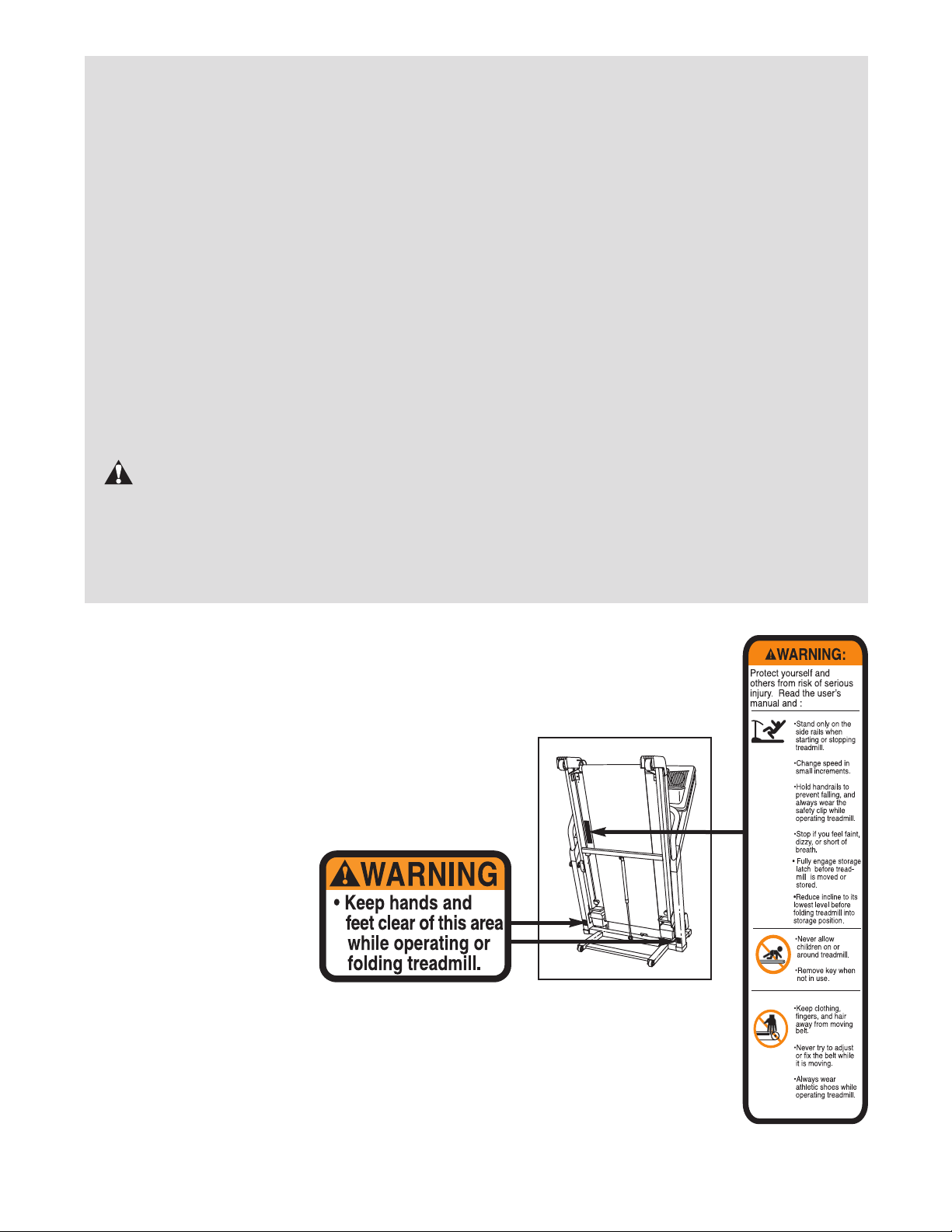
The decals shown here have been placed on your treadmill. If a decal is missing or
illegible, please call our Customer Service Department, toll-free, to order a free replacement decal (see ORDERING REPLACEMENT PARTS on page 31). Apply the
decal in the location shown. Note: The decals may not be shown at actual size.
4
BEFORE YOU BEGIN
Thank you for selecting the revolutionary NordicTrack
A2050 treadmill. The A2050 treadmill offers a selection
of features designed to make your workouts at home
more enjoyable and effective. And when you’re not exercising, the unique A2050 treadmill can be folded up,
requiring less than half the floor space of other tread
mills.
For your benefit, read this manual carefully before
using the treadmill
ing this manual, please call our Customer Service
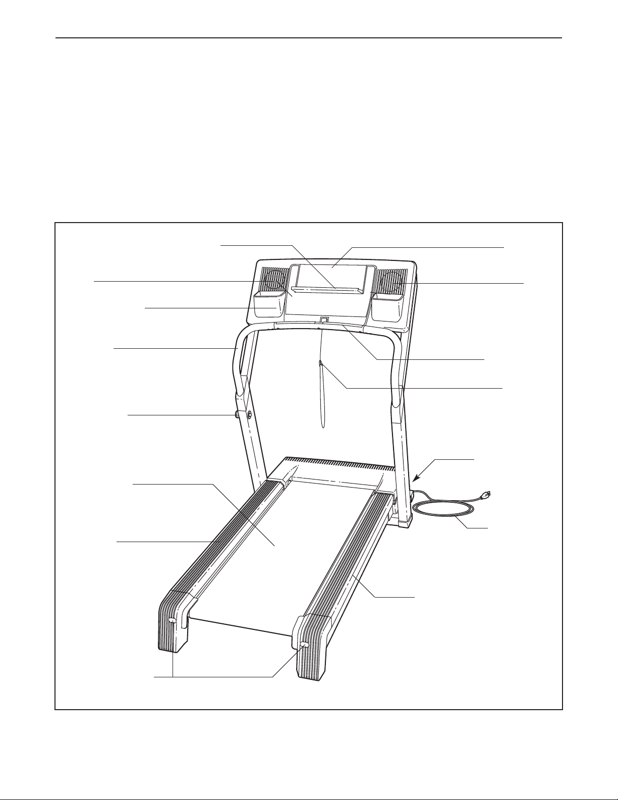
Fan
Accessory Tray
Handrail
. If you have questions after read-
Book Holder
-
®
Department toll-free at 1-888-825-2588, Monday
through Friday, 6 a.m. until 6 p.m. Mountain Time (ex
cluding holidays). To help us assist you, please note
the product model number and serial number before
calling. The model number of the treadmill is
NTL10850. The serial number can be found on a decal
attached to the treadmill (see the front cover of this
manual for the location).
Before reading further, please familiarize yourself with
the parts that are labeled in the drawing below.
Console
Pulse Sensor
-
Fan
Latch Knob
Walking Belt
Foot Rail
Rear Roller
Adjustment Bolts
Key/Clip
Reset/Off
Circuit Breaker
Power Cord
Cushioned Walking Platform
5
ASSEMBLY
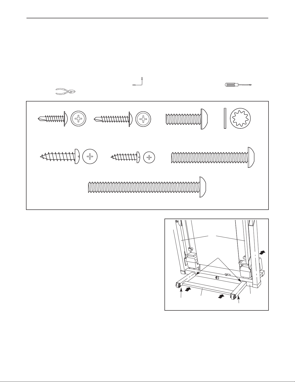
1” Tek Screw (82)–2
Console Bolt (72)–2
3/4” Tek Screw (44)–4
Pulse Bar Bolt (66)–4
Short Console
Bolt (112)–2
Star Washer (67)–8
3/4” Screw (7)–2
Extension Screw
(87)–4
Assembly requires two persons. Set the treadmill in a cleared area and remove all packing materials. Do not
dispose of the packing materials until assembly is completed.
Note: The underside of the treadmill walking belt is coated with high-performance lubricant. During shipping, a
small amount of lubricant may be transferred to the top of the walking belt or the shipping carton. This is a normal
condition and does not affect treadmill performance. If there is lubricant on top of the walking belt, simply wipe off
the lubricant with a soft cloth and a mild, non-abrasive cleaner.
Assembly requires the included allen wrench and your own phillips screwdriver and
wire cutters . For help identifying the assembly hardware, see the hardware drawings below.
1. With the help of a second person, carefully raise the
Upright Base (85) and the Frame (55) to the position
shown.
While the other person holds the Frame (55) and the
Upright Base (85), insert the Base Extension (90) into
the two brackets on the lower end of the Upright Base.
Make sure that the Base Extension is turned so the
Base Pads (81) are beneath it. Note: It may be helpful
to tip the Upright Base forward as you insert the Base
Extension.
1
81
90
55
Brackets
85
81
6
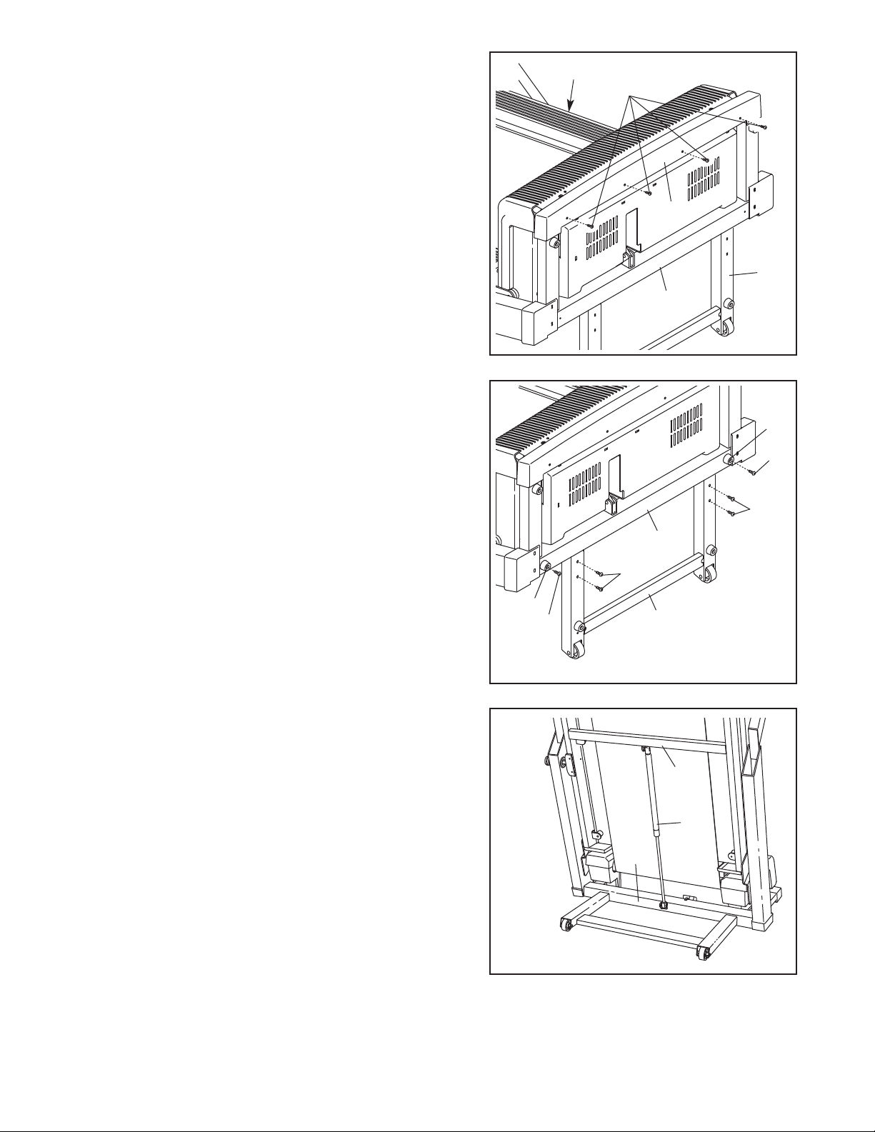
2. With the help of a second person, carefully tip the Frame
(55) and the Upright Base (85) down to the position
shown.
in the Upright Base.
Carefully slide the Base Cover (92) onto the bottom of the
Upright Base (85). Attach the Base Cover with four 3/4”
Tek Screws (44); start all four Screws before tighten-
ing them. Be careful not to overtighten the Screws.
Make sure that the Base Extension (90) remains
2
55
44
92
90
85
3. Attach the Base Extension (90) with four Extension
Screws (87);
tightening them.
Attach the two Thin Base Pads (83) to the Upright Base
(85) in the locations shown with two 1” Tek Screws (82).
Note: One replacement Base Pad may be included. Use
the Base Pad to replace any Base Pad that becomes worn.
With the help of a second person, carefully tip the Upright
Base (85) back to the vertical position.
4. With the help of a second person, raise the Frame (55) to
the vertical position.
While the other person holds the Frame (55), press the
smaller end of the Shock (86) onto the bracket in the center of the Upright Base (85).
Shock as shown. Press the other end of the Shock onto
the bracket in the center of the Frame. It may be necessay
to tip the Frame forward or back to attach the Shock. Do
not tip the Frame forward past the vertical position.
start all four Extension Screws before
Make sure to orient the
3
83
82
87
85
87
83
82
4
90
55
86
85
Carefully lower the Frame (55) to the floor.
7
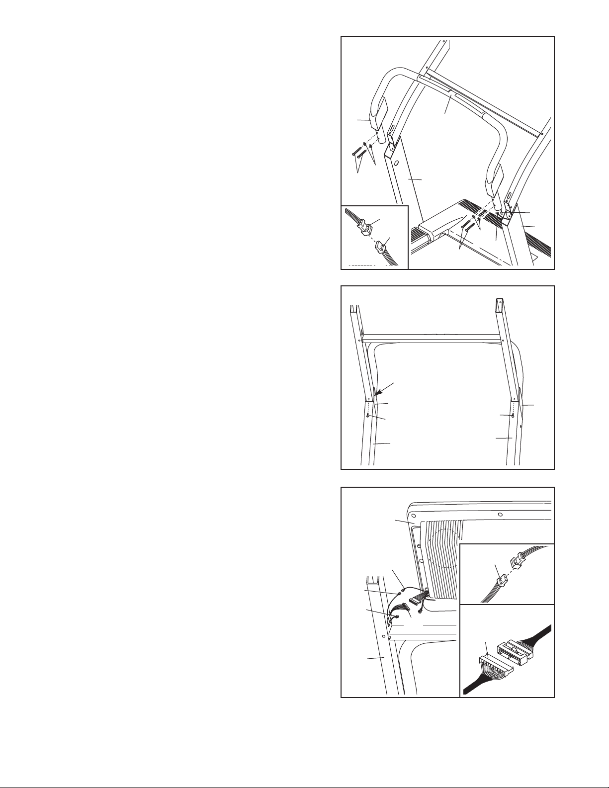
5. Slide the two Upright Covers (75) onto the ends of the
Pulse Bar (69). Align the holes in the lower ends of the
Pulse Bar with the holes in the Upright Base (85).
Cut the tie securing the Pulse Wire (74) to the Upright
Base (85). Connect the Pulse Wire to the Pulse Bar Wire
The connectors should slide together easily and
(79).
snap into place. If they do not, turn one connector
and try again. Insert the wires down into the right side of
the Upright Base (65).
5
75
69
Hold the Pulse Bar (69) against the Upright Base (85). Do
not drop the Pulse Bar into the Upright Base. Attach the
Pulse Bar to the Upright Base with the four Pulse Bar
Bolts (66) and four Star Washers (67). Be careful not to
pinch the wires. Start all four Pulse Bar Bolts before
tightening them.
Slide the Upright Covers (75) over the Pulse Bar Bolts
(66).
6. Press the two Upright Covers (75) onto the Upright Base
(85). Attach each Upright Cover with a 3/4” Screw (7). Be
careful of the the wires in the right upright.
67
66
79
74
6
75
7
Wires
85
85
79
85
67
74
66
75
7
85
7. Cut the tie securing the Wires to the Upright Base (85).
Have a second person hold the console assembly near the
Upright Base (85). Connect the Upright Wire Harness (73)
and the Pulse Wire (74) to the wires extending from the
console assembly. The connectors should slide together
easily and snap into place. If they do not, turn one connector and try again. Insert the connectors into the
Console Assembly.
Connect the Upright Ground Wire (113) to the ground wire
extending from the console assembly. Make sure that the
wires are fully inserted into each other. Insert the ground
wires into the Console Assembly.
7
Console
Assembly
Ground
Wire
113
74
73
85
74
73
8
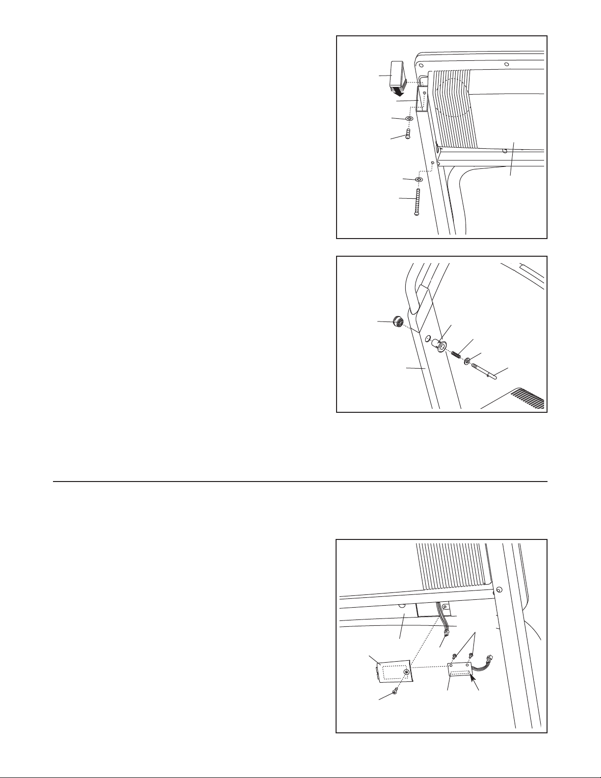
8. Set the console assembly on the Upright Base (85). Make
sure that no wires are pinched. Finger tighten a Console
(72) with a Star Washer (67) into the lower hole in
Bolt
each side of the Upright Base (only one side is shown).
8
71
Next, finger tighten a Short Console Bolt (112) with a Star
Washer (67) into the upper hole in each side of the
Upright Base (85) (only one side is shown).
not to drop the Short Console Bolt into the Upright
Base. Firmly tighten all four Console Bolts.
Press an Upright Endcap (71), with the end indicated by
the arrow first, into each side of the Upright Base (85)
(only one side is shown). Use a rubber mallet if necessary.
9. Remove the knob from the pin. Make sure that the collar
and the spring are on the pin.
Press the Latch Insert (77) into the left side of the Upright
Base (85) as shown. Use a rubber mallet if necessary.
Insert the pin into the Latch Insert. Tighten the knob back
onto the pin.
Be careful
9
Knob
67
112
85
72
67
85
Console
Assembly
77
Spring
Collar
Pin
10.Make sure that all parts are properly tightened before you use the treadmill. Keep the included allen
wrench in a secure place. The allen wrench is used to adjust the walking belt (see page 27). To protect the
floor or carpet from damage, place a mat under the treadmill.
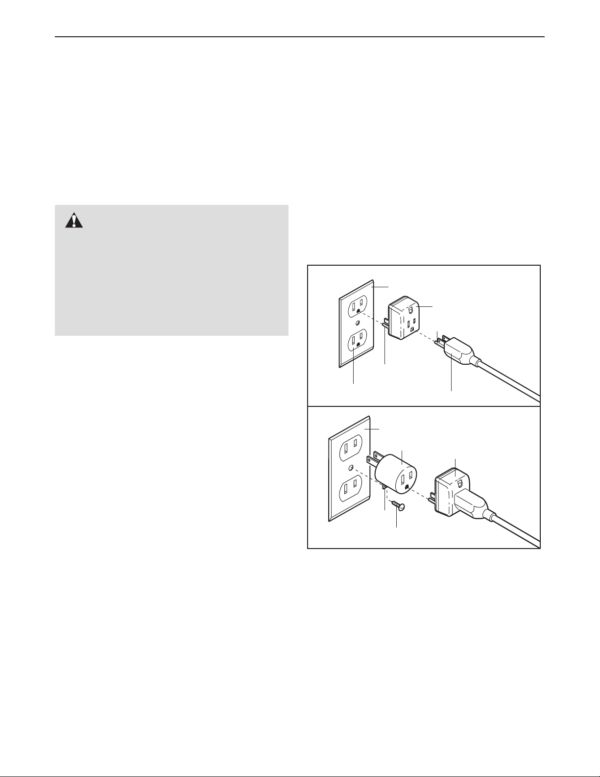
If you purchase the optional chest pulse sensor (see page 23), follow the steps below to install the receiver included with the chest pulse sensor.
1. Make sure that the power cord is unplugged. Remove
the indicated 3/4” Screw (7) and the Access Door (95)
from the left side of the Console Back (96).
Connect the wire on the receiver (A) to the indicated wire
2.
extending from the Console Back (96).
ceiver so the small cylinder is oriented as shown and
is facing the Console Back. Attach the receiver to the
plastic posts on the Access Door (95) with the two included small screws.
Make sure that no wires are pinched. Reattach the
3.
Access Door (95) with the 3/4” Screw (7). The other
wires included with the receiver may be discarded.
Hold the re-
95
Small
Screws
96
7
Wire
A
Small
Cylinder
9
OPERATION AND ADJUSTMENT
PRE-LUBRICATED WALKING BELT
THE
Your treadmill features a walking belt coated with highperformance lubricant. IMPORTANT: Never apply sil-
icone spray or other substances to the walking
belt or the walking platform. Such substances will
deteriorate the walking belt and cause excessive
wear.
HOW TO PLUG IN THE POWER CORD
DANGER: Improper connection
of the equipment-grounding conductor can
result in an increased risk of electric shock.
Check with a qualified electrician or serviceman if you are in doubt as to whether the
product is properly grounded. Do not modify
the plug provided with the product—if it will
not fit the outlet, have a proper outlet
installed by a qualified electrician.
an equipment-grounding conductor and a grounding
plug. Plug the power cord into a surge suppressor,
and plug the surge suppressor into an appropriate
outlet that is properly installed and grounded in
accordance with all local codes and ordinances.
Important: The treadmill is not compatible with
GFCI-equipped outlets.
This product is for use on a nominal 120-volt circuit,
and has a grounding plug that looks like the plug illustrated in drawing 1 below. A temporary adapter that
looks like the adapter illustrated in drawing 2 may be
used to connect the surge suppressor to a 2-pole
receptacle as shown in drawing 2 if a properly
grounded outlet is not available.
1
Grounded Outlet Box
Surge Suppressor
Grounding Pin
Your treadmill, like any other type of sophisticated
electronic equipment, can be seriously damaged by
sudden voltage changes in your home’s power.
Voltage surges, spikes, and noise interference can
result from weather conditions or from other appliances
being turned on or off. To decrease the possibility of
your treadmill being damaged, always use a surge
suppressor with your treadmill (see drawing 1 at
the right). To purchase a surge suppressor, see
your local NordicTrack dealer or call 1-888-8252588 and order part number 146148.
Use only a single-outlet surge suppressor that is
UL 1449 listed as a transient voltage surge sup
pressor (TVSS). The surge suppressor must have a
UL suppressed voltage rating of 400 volts or less
and a minimum surge dissipation of 450 joules.
The surge suppressor must be electrically rated
for 120 volts AC and 15 amps. There must be a
monitoring light on the surge suppressor to indicate whether it is functioning properly. Failure to
use a properly functioning surge suppressor could
result in damage to the control system of the
treadmill. If the control system is damaged, the
walking belt may change speed or stop unexpectedly, which may result in a fall and serious injury.
This product must be grounded.
tion or break down, grounding provides a path of least
resistance for electric current to reduce the risk of elec
tric shock. This product is equipped with a cord having
If it should malfunc-
-
Grounding Pin
Grounded Outlet
2
Grounded Outlet Box
Adapter
Lug
Metal Screw
The temporary adapter should be used only until a
properly grounded outlet (drawing 1) can be installed
by a qualified electrician.
The green-colored rigid ear, lug, or the like extending
from the adapter must be connected to a permanent
ground such as a properly grounded outlet box cover.
Whenever the adapter is used it must be held in place
by a metal screw.
covers are not grounded. Contact a qualified electrician to determine if the outlet box cover is
-
grounded before using an adapter.
Some 2-pole receptacle outlet box
Grounding Plug
Surge Suppressor
10
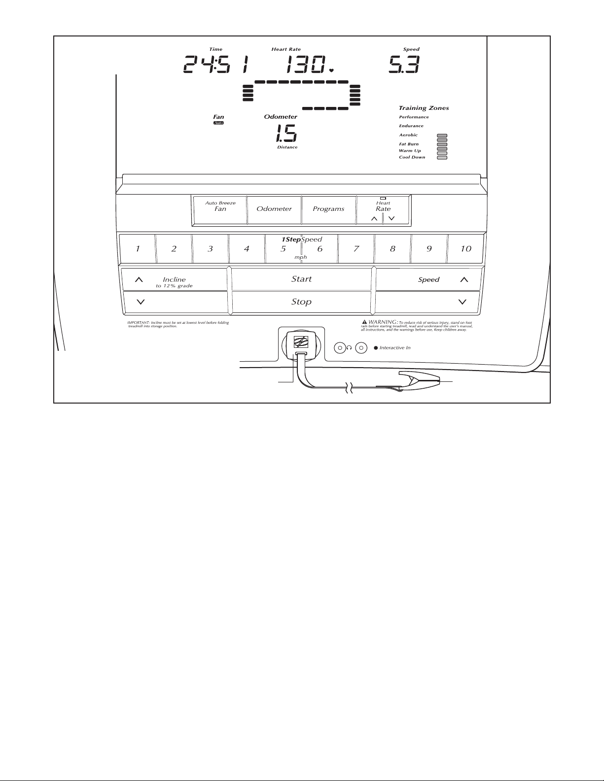
CONSOLE DIAGRAM
Note: If there is a thin sheet of plastic
on the face of the console, remove it.
FEATURES OF THE CONSOLE
The treadmill console offers an impressive array of
features designed to help you get the most from your
workouts. When the manual mode of the console is selected, the speed and incline of the treadmill can be
changed with the touch of a button. As you exercise,
the console will display continuous exercise feedback.
You can even measure your heart rate using the builtin handgrip pulse sensor or the optional chest pulse
sensor (see page 23).
In addition, the console features eight preset programs.
Each program automatically controls the speed and incline of the treadmill as it guides you through an effec
tive workout. The console also offers two heart rate programs that control the speed and incline of the treadmill
to keep your heart rate near a target heart rate during
your workouts. Note: You must wear the optional chest
pulse sensor to use the heart rate programs.
The console also features iFIT.com interactive technol
ogy. Having iFIT.com technology is like having a personal trainer in your home. Using a stereo audio cable,
Key
-
Clip
you can connect the treadmill to your portable stereo,
home stereo, computer, or VCR and play special
iFIT.com MP3, CD, and video programs (iFIT.com MP3
programs, CDs, and videocassettes are available separately). iFIT.com programs automatically control the
speed and incline of the treadmill as a personal trainer
guides you through every step of your workout; highenergy music provides added motivation.
load iFIT.com MP3 programs, go to www.iFIT.com.
To purchase iFIT.com CDs or videocassettes, call
toll-free 1-888-825-2588.
With the treadmill connected to your computer, you
can also go to www.iFIT.com and access iFIT.com
programs directly from our Web site.
www.iFIT.com for more information.
To use the manual mode of the console, follow the
steps beginning on page 12. To use a preset
program, see page 15. To use a heart rate program,
see page 16.
-
program, see page 20. To use an iFIT.com
directly from our Web site, see page 22.
To use an iFIT.com MP3, CD, or video
To down
See
-
program
1
1
 Loading...