


 Loading...
K ELECTRICAL
SECTION DI
DRIVER INFORMATION SYSTEM
CONTENTS
A
B
C
D
E
PRECAUTIONS ......................................................... |
|
3 |
Precautions for Supplemental Restraint System |
|
|
(SRS) “AIR BAG” and “SEAT BELT PRE-TEN- |
|
|
SIONER” ................................................................. |
|
3 |
COMBINATION METERS .......................................... |
|
4 |
System Description ................................................. |
|
4 |
UNIFIED METER CONTROL UNIT ..................... |
|
4 |
POWER SUPPLY AND GROUND CIRCUIT ....... |
|
4 |
SPEEDOMETER .................................................. |
|
4 |
TACHOMETER .................................................... |
|
4 |
WATER TEMPERATURE GAUGE ....................... |
|
4 |
FUEL GAUGE ...................................................... |
|
4 |
ODO/TRIP METER .............................................. |
|
5 |
AMBIENT TEMPERATURE INDICATOR ............. |
|
5 |
Arrangement of Combination Meter ........................ |
|
7 |
ComponentPartsandHarnessConnectorLocation..... |
8 |
|
Schematic ............................................................... |
|
9 |
Wiring Diagram — METER — ............................. |
... 10 |
|
AWD MODELS ................................................... |
|
10 |
2WD MODELS ................................................... |
|
12 |
Terminals and Reference Value for Combination |
|
|
Meter ..................................................................... |
|
14 |
Self-Diagnosis Mode of Combination Meter .......... |
|
14 |
SELF-DIAGNOSIS FUNCTION ......................... |
|
14 |
OPERATION PROCEDURE .............................. |
|
14 |
Trouble Diagnosis ................................................. |
|
15 |
HOW TO PERFORM WITH TROUBLE DIAGNO- |
|
|
SIS ..................................................................... |
|
15 |
PRELIMINARY CHECK ..................................... |
|
15 |
SYMPTOM CHART ............................................ |
|
15 |
Power Supply and Ground Circuit Inspection ....... |
|
16 |
Vehicle Speed Signal Inspection (With VDC) ........ |
|
16 |
Vehicle Speed Signal Inspection (Without VDC) . |
.. |
16 |
Engine Speed Signal Inspection ........................... |
|
17 |
Engine Coolant Temperature Signal Inspection .... |
|
17 |
Fuel Level Sensor Inspection ................................ |
|
17 |
Fuel Gauge Pointer Fluctuates, Indicator Wrong |
|
|
Value or Varies ...................................................... |
|
19 |
Fuel Gauge Does Not Move to FULL Position ...... |
|
19 |
Ambient Temperature Signal Inspection [Without |
|
|
Auto A/C] ............................................................... |
20 |
Ambient Temperature Signal Inspection [With Auto |
|
A/C] ........................................................................ |
21 |
Electrical Components Inspection ......................... |
22 |
FUEL LEVEL SENSOR UNIT CHECK ............... |
22 |
AMBIENT SENSOR CHECK .............................. |
22 |
Removal and Installation for Combination Meter |
... 23 |
REMOVAL .......................................................... |
23 |
INSTALLATION .................................................. |
23 |
Disassembly and Assembly for Combination Meter... 23 |
|
DISASSEMBLY .................................................. |
23 |
ASSEMBLY ........................................................ |
23 |
WARNING LAMPS ................................................... |
24 |
Schematic .............................................................. |
24 |
Wiring Diagram — WARN — ............................... |
... 25 |
AWD MODELS ................................................... |
25 |
2WD MODELS .................................................... |
31 |
Electrical Components Inspection ......................... |
37 |
OIL PRESSURE SWITCH CHECK .................... |
37 |
DIODE CHECK .................................................. |
37 |
A/T INDICATOR ....................................................... |
38 |
Wiring Diagram — AT/IND — .............................. |
... 38 |
AWD MODELS ................................................... |
38 |
2WD MODELS .................................................... |
39 |
A/T Indicator Does Not Illuminate .......................... |
40 |
WARNING CHIME .................................................... |
41 |
System Description ................................................ |
41 |
POWER SUPPLY AND GROUND CIRCUIT ...... |
41 |
IGNITION KEY WARNING CHIME .................... |
41 |
LIGHT WARNING CHIME .................................. |
41 |
SEAT BELT WARNING CHIME .......................... |
41 |
ComponentPartsandHarnessConnectorLocation... 42 |
|
Schematic .............................................................. |
43 |
Wiring Diagram — CHIME — .............................. |
... 44 |
Terminals and Reference Value for Smart Entrance |
|
Control Unit ............................................................ |
47 |
Trouble Diagnosis .................................................. |
47 |
HOW TO PERFORM WITH TROUBLE DIAGNO- |
|
SIS ...................................................................... |
47 |
SYMPTOM CHART ............................................ |
47 |
F
G
H
I
J
DI
L
M
Revision: 2006 July |
DI-1 |
2006 X-Trail |

Power Supply and Ground Circuit Inspection ........ |
47 |
[With Power Seat] .................................................. |
53 |
Front Door Switch (Driver Side) Inspection ........... |
48 |
CAN COMMUNICATION .......................................... |
55 |
Lighting Switch Input Signal Inspection ................. |
50 |
System Description ................................................ |
55 |
Key Switch Insert Signal Inspection ...................... |
50 |
CAN Communication Unit ...................................... |
55 |
Seat Belt Buckle Switch Input Signal Inspection |
|
CLOCK ..................................................................... |
56 |
[Without Power Seat] ............................................. |
51 |
Wiring Diagram — CLOCK — .............................. |
...56 |
Seat Belt Buckle Switch Input Signal Inspection |
|
|
|
Revision: 2006 July |
DI-2 |
2006 X-Trail |

|
PRECAUTIONS |
|
|
|
|
|
|
PRECAUTIONS |
PFP:00011 |
A |
|
Precautions for Supplemental Restraint System (SRS) “AIR BAG” and “SEAT |
|||
|
|||
BELT PRE-TENSIONER” |
AKS00B9V |
|
|
The Supplemental Restraint System such as “AIR BAG” and “SEAT BELT PRE-TENSIONER”, used along B |
||
with a front seat belt, helps to reduce the risk or severity of injury to the driver and front passenger for certain |
|
|
types of collision. Information necessary to service the system safely is included in the SRS and SB section of |
|
|
this Service Manual. |
C |
|
WARNING: |
||
|
||
●To avoid rendering the SRS inoperative, which could increase the risk of personal injury or death in the event of a collision which would result in air bag inflation, all maintenance must be per-
formed by an authorized NISSAN/INFINITI dealer.
●Improper maintenance, including incorrect removal and installation of the SRS, can lead to personal injury caused by unintentional activation of the system. For removal of Spiral Cable and Air
Bag Module, see the SRS section.
●Do not use electrical test equipment on any circuit related to the SRS unless instructed to in this Service Manual. SRS wiring harnesses can be identified by yellow and/or orange harnesses or
harness connectors.
D
E
F
G
H
I
J
DI
L
M
Revision: 2006 July |
DI-3 |
2006 X-Trail |

COMBINATION METERS
COMBINATION METERS
System Description
UNIFIED METER CONTROL UNIT
PFP:24814
AKS00B9X
●Speedometer, odo/trip meter, tachometer, fuel gauge and water temperature gauge are controlled by the unified meter control unit, which is built into the combination meter.
●Digital meter is adopted for odo/trip meter, ambient temperature indicator and clock.
●Meter/gauge and odo/trip meter segments can be checked in self-diagnosis mode.
POWER SUPPLY AND GROUND CIRCUIT
Power is supplied at all times
●through 10 A fuse [No. 28, located in the fuse block (J/B)]
●to combination meter terminal 1.
With the ignition switch in the ON or START position, power is supplied
●through 10 A fuse [No. 11, located in the fuse block (J/B)]
●to combination meter terminal 2.
Ground is supplied
●to combination meter terminal 21
●through grounds M27 and M70.
SPEEDOMETER
VDC/TCS/ABS control unit [with VDC] or ABS actuator and electric unit (control unit) [without VDC] provides a vehicle speed signal to the combination meter for the speedometer with CAN communication line.
TACHOMETER
The tachometer indicates engine speed in revolutions per minute (rpm).
ECM provides an engine speed signal to combination meter for tachometer with CAN communication line.
WATER TEMPERATURE GAUGE
The water temperature gauge indicates the engine coolant temperature.
ECM provides an engine coolant temperature signal to combination meter for water temperature gauge with CAN communication line.
FUEL GAUGE
The fuel gauge indicates the approximate fuel level in the fuel tank.
Combination meter reads a resistor signal from fuel level sensor unit.
Signal is supplied
●from grounds M27 and M70
●through fuel level sensor unit terminals 1 and 4
●through sub fuel level sensor unit terminals 3 and 1
●to combination meter terminal 8.
Revision: 2006 July |
DI-4 |
2006 X-Trail |

COMBINATION METERS
ODO/TRIP METER
The vehicle speed signal and the memory signals from the meter memory circuit are processed by the combi- A nation meter and the mileage is displayed.
How to Change The Display
B
Depressing the odo/trip meter switch toggles the mode in the following order.
C
D
E
F
G
H
SKIA8917E
●The odo/trip meter display mode toggling and trip display resetting can be identified by the amount of time that elapses from pressing the odo/trip meter switch to releasing it.
● When resetting with “trip A” displayed, only “trip A” display is reset. (The same way for “trip B”.) |
I |
|
|
NOTE: |
|
The record of the odo meter is kept even if the battery cable is disconnected. The record of the trip meter is |
J |
erased when the battery cable is disconnected. |
AMBIENT TEMPERATURE INDICATOR |
|
|
|
||
Combination meter displays ambient temperature on odo/trip meter. |
DI |
|
NOTE: |
||
|
||
● Indication range is between -30 and 55 ° C (-22 and 131 ° F). |
|
● |
When ambient temperature is less than -30 ° C (-22 ° F) or more than 55 ° C (131 ° F), display shows “--- L |
|
|
° C”. |
|
● |
When indicated temperature becomes less than 3 ° C (37 ° F), ambient temperature indicator flashes as |
|
|
a sign of warning. |
M |
|
|
|
Without Auto A/C
Power and ground are supplied
●from combination meter terminal 27
●through ambient sensor terminal 1 and 2
●to combination meter terminal 28
Combination meter reads ambient sensor signal from ambient sensor.
Signal is supplied
●through ambient sensor terminal 1
●to combination meter terminal 27.
Revision: 2006 July |
DI-5 |
2006 X-Trail |

COMBINATION METERS
With Auto A/C
When combination meter detects an auto A/C recognition signal from A/C auto amp., combination meter changes the ambient temperature indicator to the control for the vehicle with auto A/C.
Signal is supplied
●from A/C auto amp. terminal 28
●to combination meter terminal 29. Power and ground are supplied
●from A/C auto amp. terminal 9
●through ambient sensor terminal 1and 2
●to combination meter terminal 28 and A/C auto amp. terminal 24 Combination meter reads ambient sensor signal from ambient sensor. Signal is supplied
●through ambient sensor terminal 1
●to combination meter terminal 27.
Indication When Turning Ignition Switch OFF
●In a case that temperature detected by ambient sensor is higher than indicated temperature before turning ignition switch off.
–In a case of more than 3.5 hours after turning ignition switch off, temperature detected by ambient sensor is indicated when turning ignition switch on.
–In a case of less then 3.5 hours after turning ignition switch off, temperature at the time of turning ignition switch off is indicated.
●In a case that temperature detected by ambient sensor is lower than indicated temperature before turning ignition switch off.
–Temperature detected by ambient sensor is indicated when turning ignition switch on.
Indication During Running
Though temperature detected by ambient sensor temporarily changed, indicating temperature continentally indicates.
●In a case that temperature detected by ambient sensor is higher than indicated temperature.
–If vehicle speed is more than 20 km/h (13 MPH), elevation of indicating temperature is limited according to the speed until temperature detected by ambient sensor is indicated.
NOTE:
Vehicle speed 20 km/h (13 MPH): 256 sec., 25 km/h (16 MPH): 238 sec., 35 km/h (22 MPH): 200 sec., 50 km/h (31 MPH): 144 sec., 65 km/h (40 MPH): 88 sec., more than 80 km/h (50 MPH): 32 sec.
–If vehicle speed is more than 20 km/h (13 MPH), and that temperature detected by ambient sensor becomes 8 ° C (46 ° F) more than indicating temperature, indicating temperature will be elevated unit the
degree becomes same as temperature detected by ambient sensor with limiting elevation of indicating temperature 1 ° C par a minute.
–If vehicle speed is less than 20 km/h (13 MPH), indicating temperature is continually kept.
● In a case that temperature detected by ambient sensor is lower than indicated temperature.
–Temperature detected by ambient sensor is indicated during running.
Revision: 2006 July |
DI-6 |
2006 X-Trail |
COMBINATION METERS
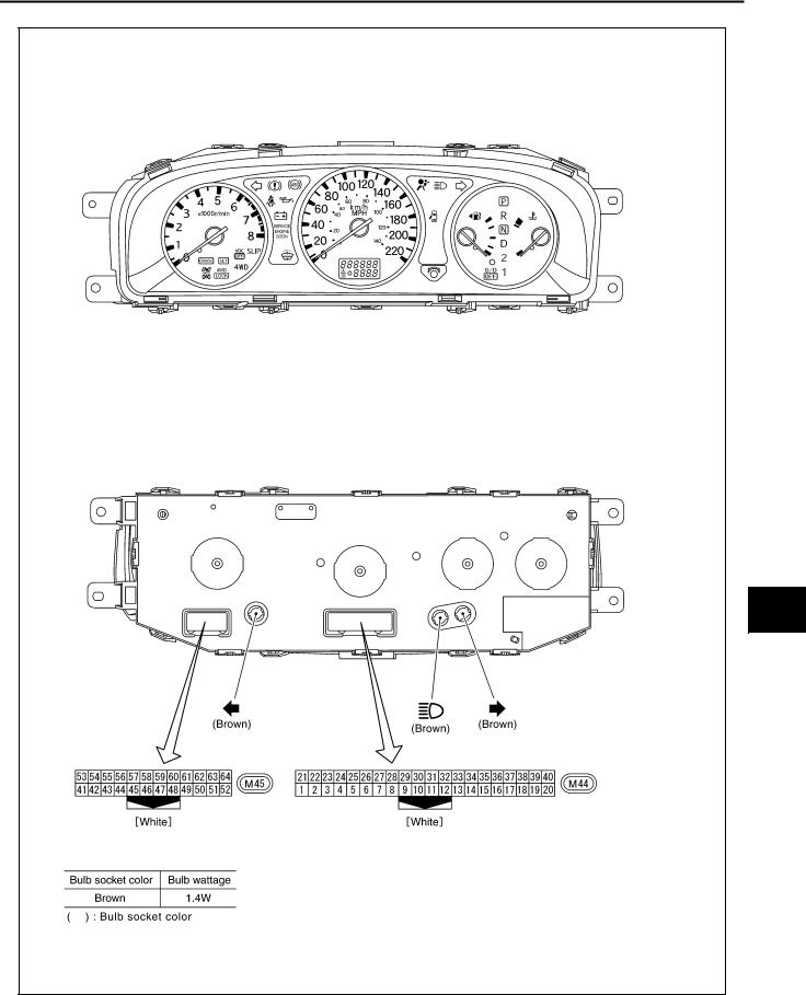
Arrangement of Combination Meter
AKS00BA1
A
B
C
D
E
F
G
H
I
J
DI
L
M
SKIB0505E
Revision: 2006 July |
DI-7 |
2006 X-Trail |
COMBINATION METERS
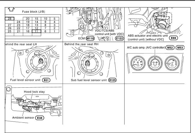
Component Parts and Harness Connector Location AKS00BA0
SKIB0506E
Revision: 2006 July |
DI-8 |
2006 X-Trail |
COMBINATION METERS
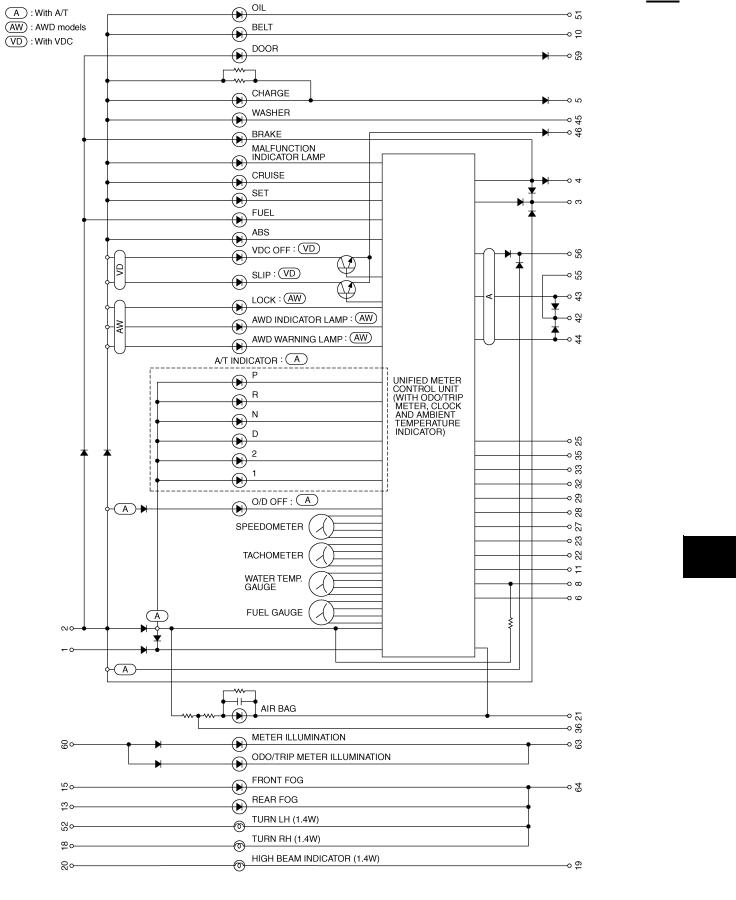
Schematic
AKS00BA2
A
B
C
D
E
F
G
H
I
J
DI
L
M
TKWB2259E
Revision: 2006 July |
DI-9 |
2006 X-Trail |

COMBINATION METERS
Wiring Diagram — METER —
AWD MODELS
AKS00BA3
TKWB2260E
Revision: 2006 July |
DI-10 |
2006 X-Trail |
COMBINATION METERS
A
B
C
D
E
F
G
H
I
J
DI
L
M
TKWB0172E
Revision: 2006 July |
DI-11 |
2006 X-Trail |

COMBINATION METERS
2WD MODELS
TKWB2261E
Revision: 2006 July |
DI-12 |
2006 X-Trail |

COMBINATION METERS
A
B
C
D
E
F
G
H
I
J
DI
L
M
TKWB0174E
Revision: 2006 July |
DI-13 |
2006 X-Trail |

COMBINATION METERS
Terminals and Reference Value for Combination Meter |
AKS00BA6 |
||||||
|
|
|
|
|
|
||
Terminal |
Wire |
|
|
Condition |
Reference Value |
||
Item |
|
|
|
||||
No. |
Color |
Ignition |
Operation or condition |
(Approx.) |
|||
|
|||||||
|
switch |
||||||
|
|
|
|
||||
|
|
|
|
|
|
||
|
|
|
|
|
|
|
|
1 |
L |
Battery power supply |
OFF |
|
— |
Battery voltage |
|
|
|
|
|
|
|
|
|
2 |
Y/G |
Ignition power supply |
ON |
|
— |
Battery voltage |
|
|
|
|
|
|
|
|
|
8 |
G |
Fuel level sensor signal |
— |
|
— |
Refer to DI-22, "FUEL LEVEL SEN- |
|
|
SOR UNIT CHECK" . |
||||||
|
|
|
|
|
|
||
|
|
|
|
|
|
|
|
21 |
B |
Ground |
ON |
|
— |
0 V |
|
|
|
|
|
|
|
|
|
22 |
W |
CAN-H |
— |
|
— |
— |
|
|
|
|
|
|
|
|
|
23 |
R |
CAN-L |
— |
|
— |
— |
|
|
|
|
|
|
|
|
|
27 |
R/B |
Ambient sensor signal |
— |
|
— |
Refer to DI-22, "AMBIENT SENSOR |
|
|
CHECK" |
||||||
|
|
|
|
|
|
||
|
|
|
|
|
|
|
|
28 |
B/Y |
Ambient sensor ground |
ON |
|
— |
0 V |
|
|
|
|
|
|
|
|
|
29*1 |
Y |
Auto A/C recognition signal |
ON |
|
— |
5 V |
|
NOTE: |
|
|
|
|
|
|
|
*1:With auto A/C |
|
|
|
|
|
||
Self-Diagnosis Mode of Combination Meter |
|
AKS00BA7 |
|||||
SELF-DIAGNOSIS FUNCTION
●Odo/trip meter segment can be checked in self-diagnosis mode.
●Meters/gauges can be checked in self-diagnosis mode.
OPERATION PROCEDURE
1.Turn the ignition switch ON, and switch the odo/trip meter to “trip A” or “trip B”.
NOTE:
If the diagnosis function is activated with “trip A” displayed, the mileage on “trip A” will indicate 0.0 mile, but the actual trip mileage will be retained. (The same way for “trip B”.)
2.Turn ignition switch OFF.
3.While pushing the odo/trip meter switch, turn ignition switch ON again.
4.Make sure that the trip meter displays “0.0”.
5.Push the odo/trip meter switch at least 3 times. (Within 7 seconds after the ignition switch is turned ON.)
6.All the segments on the odo/trip meter illuminate, and simultaneously the low-fuel warning lamp indicator illuminates. At this time, the unified meter control unit is turned to self-diagnosis mode.
NOTE:
●Check combination meter power supply and ground circuit when self-diagnosis mode of combination meter does not start. Replace combination meter if normal.
●If any of the segments is not displayed, replace combination meter.
SKIA8920E
Revision: 2006 July |
DI-14 |
2006 X-Trail |

COMBINATION METERS
7.Each meter activates during pressing odo/trip meter switch. (Then low-fuel warning lamp turns OFF.)
NOTE:
If any of the meter and gages is not activated, replace combination meter.
|
SKIB0507E |
Trouble Diagnosis |
AKS00BQ6 |
HOW TO PERFORM WITH TROUBLE DIAGNOSIS |
|
1.Confirm the symptom or customer complaint.
2.Perform preliminary check. Refer to DI-15, "PRELIMINARY CHECK" .
3.According to the symptom chart, make sure cause of the symptom and repair or replace applicable parts. Refer to DI-15, "SYMPTOM CHART" .
4.Does the meter operate normally? If so, GO TO 5. If not, GO TO 2.
5.INSPECTION END
PRELIMINARY CHECK
1. CHECK COMBINATION METER (SELF-DIAGNOSIS MODE)
Perform self-diagnosis mode of combination. Refer to DI-14, "Self-Diagnosis Mode of Combination Meter" . Does self-diagnosis mode operate normally?
YES |
>> INSPECTION END |
NO |
>> GO TO 3. |
2. CHECK POWER SUPPLY AND GROUND CIRCUIT OF COMBINATION METER
Check power supply and ground circuit of combination meter.
OK or NG |
|
||
OK |
>> Replace combination meter. |
|
|
NG |
>> Repair power supply and ground circuit of combination meter. |
||
SYMPTOM CHART |
|
||
|
|
|
|
|
Symptom |
Possible cause |
|
|
|
|
|
Speedometer and odo/trip meter indication are malfunction. |
Refer to DI-16, "Vehicle Speed Signal Inspection (With VDC)" or DI- |
||
16, "Vehicle Speed Signal Inspection (Without VDC)" . |
|||
|
|
||
|
|
||
Tachometer indication is malfunction. |
Refer to DI-17, "Engine Speed Signal Inspection" . |
||
|
|
||
Water temperature gauge indication is malfunction. |
Refer to DI-17, "Engine Coolant Temperature Signal Inspection" . |
||
|
|
||
Low-fuel warning lamp indication is irregular. |
Refer to DI-17, "Fuel Level Sensor Inspection" . |
||
|
|
||
Fuel gauge indication is malfunction. |
|||
|
|||
|
|
|
|
|
|
Refer to DI-20, "Ambient Temperature Signal Inspection [Without Auto |
|
Ambient temperature indicator is malfunction. |
A/C]" or DI-21, "Ambient Temperature Signal Inspection [With Auto A/ |
||
|
|
C]" . |
|
|
|
||
A/T position indicator is malfunction. |
Refer to DI-40, "A/T Indicator Does Not Illuminate" . |
||
|
|
|
|
A
B
C
D
E
F
G
H
I
J
DI
L
M
Revision: 2006 July |
DI-15 |
2006 X-Trail |

COMBINATION METERS
Power Supply and Ground Circuit Inspection |
AKS00BAA |
||||
1. CHECK FUSE |
|
|
|
||
Check for blown combination meter fuses. |
|
|
|
||
|
|
|
|
|
|
|
Unit |
|
Power source |
Fuse No. |
|
|
|
|
|
|
|
|
Combination meter |
|
Battery |
28 |
|
|
|
|
|
|
|
|
|
Ignition switch (ON) |
11 |
|
|
|
|
|
|
||
|
|
|
|
|
|
OK or NG |
|
|
|
||
OK |
>> GO TO 2. |
|
|
|
|
NG |
>> If fuse is blown, be sure to eliminate cause of malfunction before installing new fuse. Refer to PG- |
||||
|
51, "FUSE BLOCK - JUNCTION BOX (J/B)" . |
|
|
||
2. CHECK POWER SUPPLY CIRCUIT
Check voltage between combination meter and ground.
|
|
|
Terminals |
|
Ignition switch position |
|
|
|
|
|
|
|
|
|
|
(+) |
(–) |
OFF |
ON |
|
|
|
|
|
|||
|
Connector |
Terminal (Wire color) |
|
|
|
|
|
|
|
|
|
|
|
|
M44 |
|
2 (Y/G) |
Ground |
0 V |
Battery voltage |
|
|
|
|
|
||
|
|
1 (L) |
Battery voltage |
Battery voltage |
||
|
|
|
|
|||
|
|
|
|
|
|
|
OK or NG |
|
|
|
|||
|
OK |
>> GO TO 3. |
|
|
|
|
|
NG |
>> Repair harness between combination meter and fuse. |
||||
3. CHECK GROUND CIRCUIT
1.Turn ignition switch OFF.
2.Disconnect combination meter connector.
3.Check continuity between combination meter harness connector M44 terminal 21 (B) and ground.
|
21 (B) – Ground |
: Continuity should exist. |
OK or NG |
|
|
OK |
>> Power supply and ground circuit is OK. |
|
NG |
>> Repair ground harness. |
|
SKIB0600E
SKIB0601E
Vehicle Speed Signal Inspection (With VDC) |
AKS00BLQ |
1. CHECK VDC/TCS/ABS CONTROL UNIT (CONSULT-II)
Preform VDC/TCS/ABS control unit self-diagnosis. Refer to BRC-60, "CONSULT-II Functions (ABS)" . Self-diagnosis results
No malfunction detected>>Replace combination meter.
Malfunction detected>>Check applicable parts, and repair or replace corresponding parts.
Vehicle Speed Signal Inspection (Without VDC) |
AKS00BAG |
1. CHECK ABS ACTUATOR AND ELECTRIC UNIT (CONSULT-II)
Preform ABS actuator and electric unit self-diagnosis. Refer to BRC-18, "CONSULT-II Functions (ABS)" . Self-diagnosis results
No malfunction detected>>Replace combination meter.
Malfunction detected>>Check applicable parts, and repair or replace corresponding parts.
Revision: 2006 July |
DI-16 |
2006 X-Trail |

COMBINATION METERS
Engine Speed Signal Inspection |
AKS00BAE |
|
1. CHECK ECM (CONSULT-II) |
|
A |
|
|
|
Perform ECM self-diagnosis. Refer to EC-112, "CONSULT-II Function (ENGINE)" . |
|
|
Self-diagnosis results |
|
B |
No malfunction detected>>Replace combination meter.
Malfunction detected>>Check applicable parts, and repair or replace corresponding parts.
Engine Coolant Temperature Signal Inspection |
AKS00BAF |
1. CHECK ECM (CONSULT-II)
Perform ECM self-diagnosis. Refer to EC-112, "CONSULT-II Function (ENGINE)" . Self-diagnosis results
No malfunction detected>>Replace combination meter.
Malfunction detected>>Check applicable parts, and repair or replace corresponding parts.
Fuel Level Sensor Inspection |
AKS00BAC |
NOTE:
The following symptoms are not malfunction.
FUEL GAUGE
●Depending on vehicle posture or driving circumstances, fuel level in tank varies, and the pointer may fluctuate.
●If the vehicle is fueled with ignition switch ON, the pointer moves slowly.
LOW-FUEL WARNING LAMP
C
D
E
F
G
H
●Depending on vehicle posture or driving circumstances, fuel level in tank varies, and warning lamp ON timing may change.
1. CHECK HARNESS CONNECTOR
Check combination meter and fuel level sensor unit terminals (meter side, unit side, harness side) for looseness or bent terminals.
OK or NG
OK |
>> GO TO 2. |
NG |
>> Repair terminal or connector. |
2. CHECK COMBINATION METER CIRCUIT
1.Turn ignition switch OFF.
2.Disconnect combination meter connector and sub fuel level sensor unit connector.
3.Check continuity between combination meter harness connector M44 terminal 8 (G) and sub fuel level sensor unit harness connector B125 terminal 1 (G).
8 (G) – 1 (G) |
: Continuity should exist. |
4.Check continuity between combination meter harness connector M44 terminal 8 (G) and ground.
|
8 (G) – Ground |
: Continuity should not exist. |
|
|
|
|
SKIA8924E |
OK or NG |
|
|
|
OK |
>> GO TO 3. |
|
|
NG |
>> Repair harness or connector. |
||
I
J
DI
L
M
Revision: 2006 July |
DI-17 |
2006 X-Trail |
Loading...