


 Loading...
H RESTRAINTS
SECTION SRS
SUPPLEMENTAL RESTRAINT SYSTEM (SRS)
CONTENTS
A
B
C
D
E
PRECAUTIONS ......................................................... |
|
2 |
Precautions for Supplemental Restraint System |
|
|
(SRS) “AIR BAG” and “SEAT BELT PRE-TEN- |
|
|
SIONER” ................................................................. |
|
2 |
Precautions for SRS “AIR BAG” and “SEAT BELT |
||
PRE-TENSIONER” Service .................................... |
|
2 |
PREPARATION .......................................................... |
|
3 |
Commercial Service Tools ....................................... |
|
3 |
SUPPLEMENTAL RESTRAINT SYSTEM (SRS) ...... |
|
4 |
SRS Configuration .................................................. |
|
4 |
Front Seat Belt Pre-Tensioner with Load Limiter |
..... |
5 |
Front Side Air Bag ................................................... |
|
5 |
TROUBLE DIAGNOSIS ............................................. |
|
6 |
Trouble Diagnosis Introduction ................................ |
|
6 |
DIAGNOSIS FUNCTION ...................................... |
|
6 |
HOW TO PERFORM TROUBLE DIAGNOSES |
|
|
FOR QUICK AND ACCURATE REPAIR .............. |
|
6 |
WORK FLOW ....................................................... |
|
7 |
Component Parts Location ...................................... |
|
8 |
Wiring Diagram — SRS — .................................. |
..... 9 |
|
CONSULT-II Function ............................................ |
|
11 |
DIAGNOSIS MODE FOR CONSULT-II ............... |
|
11 |
HOW TO CHANGE SELF-DIAGNOSIS MODE |
|
|
WITH CONSULT-II .............................................. |
|
11 |
HOW TO ERASE SELF-DIAGNOSIS RESULTS... |
12 |
|
Self-Diagnosis Function (Without CONSULT-II) .... |
|
12 |
HOW TO CHANGE SELF-DIAGNOSIS MODE |
|
|
WITHOUT CONSULT-II ..................................... |
|
12 |
HOW TO ERASE SELF-DIAGNOSIS RESULTS... |
12 |
|
SRS Operation Check ........................................... |
|
13 |
DIAGNOSTIC PROCEDURE 1 .......................... |
|
13 |
Trouble Diagnosis with CONSULT–II .................... |
|
15 |
DIAGNOSTIC PROCEDURE 2 .......................... |
|
15 |
DIAGNOSTIC PROCEDURE 3 .......................... |
|
19 |
DIAGNOSTIC PROCEDURE 4 (CONTINUED |
|
|
FROM DIAGNOSTIC PROCEDURE 2) ............. |
|
21 |
DIAGNOSTIC PROCEDURE 5 .......................... |
|
21 |
Trouble Diagnosis without CONSULT-II ................ |
|
26 |
DIAGNOSTIC PROCEDURE 6 .......................... |
|
26 |
WARNING LAMP FLASH CODE CHART .......... |
|
26 |
Trouble Diagnosis: “AIR BAG” Warning Lamp Does |
|
Not Turn OFF ........................................................ |
29 |
DIAGNOSTIC PROCEDURE 7 .......................... |
29 |
Trouble Diagnosis: “AIR BAG” Warning Lamp Does |
|
Not Turn ON .......................................................... |
30 |
DIAGNOSTIC PROCEDURE 8 .......................... |
30 |
DRIVER AIR BAG MODULE ................................... |
31 |
Removal and Installation ....................................... |
31 |
REMOVAL .......................................................... |
31 |
INSTALLATION .................................................. |
32 |
SPIRAL CABLE ....................................................... |
34 |
Removal and Installation ....................................... |
34 |
REMOVAL .......................................................... |
34 |
INSTALLATION .................................................. |
35 |
FRONT PASSENGER AIR BAG MODULE ............. |
36 |
Removal and Installation ....................................... |
36 |
REMOVAL .......................................................... |
36 |
INSTALLATION .................................................. |
36 |
SIDE AIR BAG (SATELLITE) SENSOR .................. |
37 |
Removal and Installation ....................................... |
37 |
REMOVAL .......................................................... |
37 |
INSTALLATION .................................................. |
37 |
FRONT SEAT BELT PRE-TENSIONER .................. |
38 |
Removal and Installation ....................................... |
38 |
DIAGNOSIS SENSOR UNIT .................................... |
39 |
Removal and Installation ....................................... |
39 |
REMOVAL .......................................................... |
39 |
INSTALLATION .................................................. |
39 |
ECU DISCRIMINATED NO. ............................... 39 |
|
COLLISION DIAGNOSIS ......................................... |
40 |
For Frontal Collision .............................................. |
40 |
SRS INSPECTION (FOR FRONTAL COLLI- |
|
SION) ................................................................. |
40 |
For Side Collision .................................................. |
42 |
WHEN THE SIDE AIR BAG IS ACTIVATED IN |
|
THE SIDE COLLISION: ...................................... |
42 |
WHEN SRS IS NOT ACTIVATED IN THE SIDE |
|
COLLISION: ....................................................... |
42 |
SRS INSPECTION (FOR SIDE COLLISION) ..... |
42 |
F
G
SRS
I
J
K
L
M
Revision: 2006 July |
SRS-1 |
2006 X-Trail |
|
PRECAUTIONS |
|
|
PRECAUTIONS |
PFP:00001 |
Precautions for Supplemental Restraint System (SRS) “AIR BAG” and “SEAT BELT PRE-TENSIONER” AHS000QA
The Supplemental Restraint System such as “AIR BAG” and “SEAT BELT PRE-TENSIONER”, used along with a front seat belt, helps to reduce the risk or severity of injury to the driver and front passenger for certain types of collision. Information necessary to service the system safely is included in the SRS and SB section of this Service Manual.
WARNING:
●To avoid rendering the SRS inoperative, which could increase the risk of personal injury or death in the event of a collision which would result in air bag inflation, all maintenance must be performed by an authorized NISSAN/INFINITI dealer.
●Improper maintenance, including incorrect removal and installation of the SRS, can lead to personal injury caused by unintentional activation of the system. For removal of Spiral Cable and Air Bag Module, see the SRS section.
●Do not use electrical test equipment on any circuit related to the SRS unless instructed to in this Service Manual. SRS wiring harnesses can be identified by yellow and/or orange harnesses or harness connectors.
Precautions for SRS “AIR BAG” and “SEAT BELT PRE-TENSIONER” Service
AHS000QB
●Do not use electrical test equipment to check SRS circuits unless instructed to in this Service Manual.
●Before servicing the SRS, turn ignition switch OFF, disconnect both battery cables and wait at least 3 minutes.
For approximately 3 minutes after the cables are removed, it is still possible for the air bag and seat belt pre-tensioner to deploy. Therefore, do not work on any SRS connectors or wires until at least 3 minutes have passed.
●Diagnosis sensor unit must always be installed with their arrow marks “ ” pointing towards the front of the vehicle for proper operation. Also check diagnosis sensor unit for cracks, deformities or rust before installation and replace as required.
●The spiral cable must be aligned with the neutral position since its rotations are limited. Do not attempt to turn steering wheel or column after removal of steering gear.
●Handle air bag module carefully. Always place driver and front passenger air bag modules with the pad side facing upward and place front side air bag module standing with stud bolt side setting bottom.
●Conduct self-diagnosis to check entire SRS for proper function after replacing any components.
●After air bag inflates, the front instrument panel assembly should be replaced if damaged.
Revision: 2006 July |
SRS-2 |
2006 X-Trail |

PREPARATION
PREPARATION
Commercial Service Tools
Tool name |
Description |
Tamper resistant TORX bit |
Size: T30 |
|
S-NT757 |
PFP:00002
A
AHS000QE
B
C
D
E
F
G
SRS
I
J
K
L
M
Revision: 2006 July |
SRS-3 |
2006 X-Trail |

SUPPLEMENTAL RESTRAINT SYSTEM (SRS)
SUPPLEMENTAL RESTRAINT SYSTEM (SRS)
SRS Configuration
PFP:28556
AHS000QF
PHIA0037E
The air bag deploys if the diagnosis sensor unit activates while the ignition switch is in the ON or START position.
The collision modes for which supplemental restraint systems are activated are different among the SRS systems. For example, the driver air bag module and front passenger air bag module are activated in a frontal collision but not in a side collision.
SRS configurations which are activated for some collision modes are as follows;
SRS configuration |
Frontal collision |
Left side collision |
Right side collision |
|
|
|
|
Driver air bag module |
× |
— |
— |
|
|
|
|
Front passenger air bag module |
× |
— |
— |
|
|
|
|
Front LH seat belt pre-tensioner |
× |
— |
— |
|
|
|
|
Front RH seat belt pre-tensioner |
× |
— |
— |
|
|
|
|
Front LH side air bag module |
— |
× |
— |
|
|
|
|
Front RH side air bag module |
— |
— |
× |
|
|
|
|
Revision: 2006 July |
SRS-4 |
2006 X-Trail |

SUPPLEMENTAL RESTRAINT SYSTEM (SRS)
Front Seat Belt Pre-Tensioner with Load Limiter
The seat belt pre-tensioner system with load limiter is installed to both the driver's seat and the front passenger's seat. It operates simultaneously with the SRS air bag system in the event of a frontal collision with an impact exceeding a specified level.
When the frontal collision with an impact exceeding a specified level occurs, seat belt slack resulting from clothing or other factors is immediately taken up by the pre-tensioner. Vehicle passengers are securely restrained.
When passengers in a vehicle are thrown forward in a collision and the restraining force of the seat belt exceeds a specified level, the load limiter permits the specified extension of the seat belt by the twisting of the ELR shaft, and a relaxation of the chest-area seat belt web tension while maintaining force.
Front Side Air Bag
Front side air bag is built-in type.
The front seatbacks with built-in type side air bag have the labels shown in figure at right.
AHS000QG
A
B
C
D
SRS444
E
AHS000QH
F
G
SRS
PHIA0039E
I
J
K
L
M
Revision: 2006 July |
SRS-5 |
2006 X-Trail |

TROUBLE DIAGNOSIS
TROUBLE DIAGNOSIS |
PFP:00004 |
Trouble Diagnosis Introduction |
AHS000QI |
CAUTION:
●Do not use electrical test equipment on any circuit related to the SRS unless instructed to in this Service Manual. SRS wiring harness can be identified by yellow and/or orange harnesses or harness connector.
●Do not attempt to repair, splice or modify the SRS wiring harness. If the harness is damaged, replace it with a new one.
●Keep ground portion clean.
DIAGNOSIS FUNCTION
The SRS self-diagnosis results can be read by using “AIR BAG” warning lamp and/or CONSULT-II.
The User mode is exclusively prepared for the customer (driver). This mode warns the driver of a system malfunction through the operation of the “AIR BAG” warning lamp.
The Diagnosis mode allows the technician to locate and inspect the malfunctioning part. The mode applications for the “AIR BAG” warning lamp and CONSULT-II are as follows:
|
User mode |
Diagnosis mode |
Display type |
|
|
|
|
“AIR BAG” warning lamp |
X |
X |
ON-OFF operation |
|
|
|
|
CONSULT-II |
— |
X |
Monitoring |
|
|
|
|
NOTE:
Seat belt pre-tensioner malfunction is indicated by “AIR BAG” warning lamp.
HOW TO PERFORM TROUBLE DIAGNOSES FOR QUICK AND ACCURATE REPAIR
A good understanding of the malfunction conditions can make troubleshooting faster and more accurate.
In general, each customer feels differently about a malfunction. It is important to fully understand the symptoms or conditions for a customer complaint.
Information from Customer
WHAT..... |
Vehicle model |
WHEN..... |
Date, Frequencies |
WHERE..... |
Road conditions |
HOW..... |
Operating conditions, Symptoms |
Preliminary Check
Check that the following parts are in good order.
●Battery (Refer to SC-4, "How to Handle Battery" .)
●Fuse (Refer to SRS-9, "Wiring Diagram — SRS — " .)
●System component-to-harness connections
Revision: 2006 July |
SRS-6 |
2006 X-Trail |
TROUBLE DIAGNOSIS
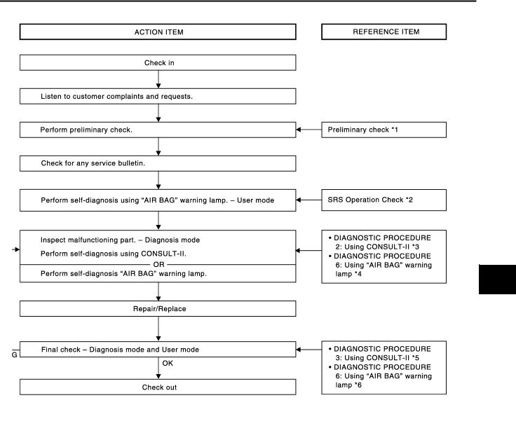
WORK FLOW
|
|
|
|
|
PHIA0217E |
*1: |
SRS-6, "Preliminary Check". |
*2: |
SRS-13, "SRS Operation Check". |
*3: |
SRS-15, "DIAGNOSTIC PROCE- |
|
|
|
|
|
DURE 2". |
*4: |
SRS-26, "DIAGNOSTIC PROCE- |
*5: |
SRS-19, "DIAGNOSTIC PROCE- |
*6: |
SRS-26, "DIAGNOSTIC PROCE- |
|
DURE 6". |
|
DURE 3". |
|
DURE 6". |
A
B
C
D
E
F
G
SRS
I
J
K
L
M
Revision: 2006 July |
SRS-7 |
2006 X-Trail |
TROUBLE DIAGNOSIS
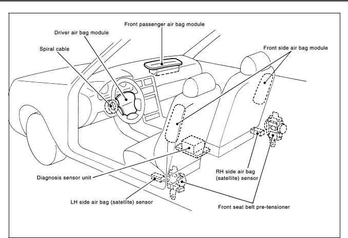
Component Parts Location
AHS000QJ
PHIA0020E
Revision: 2006 July |
SRS-8 |
2006 X-Trail |

TROUBLE DIAGNOSIS
Wiring Diagram — SRS —
AHS000QK
A
B
C
D
E
F
G
SRS
I
J
K
L
M
THWA0031E
Revision: 2006 July |
SRS-9 |
2006 X-Trail |

TROUBLE DIAGNOSIS
THWA0032E
Revision: 2006 July |
SRS-10 |
2006 X-Trail |
TROUBLE DIAGNOSIS
CONSULT-II Function |
AHS000QM |
DIAGNOSIS MODE FOR CONSULT-II
●“SELF-DIAG [CURRENT]”
A current Self-diagnosis result (also indicated by the number of warning lamp flashes in the Diagnosis mode) is displayed on the CONSULT-II screen in real time. This refers to a malfunctioning part requiring repairs.
●“SELF-DIAG [PAST]”
Diagnosis results previously stored in the memory are displayed on the CONSULT-II screen. The stored results are not erased until memory erasing is executed.
●“TROUBLE DIAG RECORD”
With TROUBLE DIAG RECORD, diagnosis results previously erased by a reset operation can be displayed on the CONSULT-II screen.
●“ECU DISCRIMINATED NO.”
The diagnosis sensor unit for each vehicle model is assigned with its own, individual classification number. This number will be displayed on the CONSULT-II screen, as shown. When replacing the diagnosis sensor unit, refer to the part number for the compatibility. After installation, replacement with a correct unit can be checked by confirming this classification number on the CONSULT-II screen.
After repair, make sure the discriminated number of diagnosis sensor unit installed to vehicle are same. Refer to SRS-39, "ECU DISCRIMINATED NO." .
PHIA0218E
HOW TO CHANGE SELF-DIAGNOSIS MODE WITH CONSULT-II
From User Mode to Diagnosis Mode
A
B
C
D
E
F
G
SRS
After selecting “AIR BAG” on the “SELECT SYSTEM” screen, User mode automatically changes to Diagnosis |
I |
|||
mode. |
||||
|
|
|
J |
|
|
|
|
||
|
|
|
K |
|
|
|
|
L |
|
|
SRS803 |
|
|
|
From Diagnosis Mode to User Mode |
M |
|||
To return to User mode from Diagnosis mode, touch “BACK” key of CONSULT-II until “SELECT SYSTEM” |
||||
|
||||
appears, then diagnosis mode automatically changes to User mode. |
|
|||
SRS804
Revision: 2006 July |
SRS-11 |
2006 X-Trail |

TROUBLE DIAGNOSIS
HOW TO ERASE SELF-DIAGNOSIS RESULTS
●“SELF-DIAG [CURRENT]”
A current Self-diagnosis result is displayed on the CONSULT-II screen in real time.
After the malfunction is repaired completely, no malfunction is detected on “SELF-DIAG [CURRENT]”.
●“SELF-DIAG [PAST]”
Return to the “SELF-DIAG [CURRENT]” CONSULT-II screen by touching “BACK” key of CONSULT-II and select “SELF-DIAG [CURRENT]” in SELECT DIAG MODE. Touch “ERASE” in “SELF-DIAG [CURRENT]” mode.
NOTE:
If the memory of the malfunction in “SELF-DIAG [PAST]” is not erased, the User mode shows the system malfunction by the operation of the warning lamp even if the malfunction is repaired completely.
●“TROUBLE DIAG RECORD”
The memory of “TROUBLE DIAG RECORD” cannot be erased.
Self-Diagnosis Function (Without CONSULT-II)
SRS701
AHS000QN
●The reading of these results is accomplished “User mode” and “Diagnosis mode”.
●After a malfunction is repaired, turn ignition switch ON. Diagnosis mode returns to the User mode. At that time, the self-diagnostic result is cleared.
HOW TO CHANGE SELF-DIAGNOSIS MODE WITHOUT CONSULT-II
PHIA0709E
HOW TO ERASE SELF-DIAGNOSIS RESULTS
After a malfunction is repaired, turn the ignition switch OFF for at least one second, then back ON. Diagnosis mode returns to the User mode. At that time, the self-diagnostic result is cleared.
Revision: 2006 July |
SRS-12 |
2006 X-Trail |

|
TROUBLE DIAGNOSIS |
|
|
|
|
SRS Operation Check |
AHS000QO |
|
DIAGNOSTIC PROCEDURE 1 |
|
A |
Checking Air Bag Operation by Using “AIR BAG” Warning Lamp — User Mode
1.Turn the ignition switch from OFF to ON, and check that the air bag warning lamp blinks.
2. Compare the SRS air bag warning lamp blinking pattern with the |
|
|
B |
|
|
||
|
|
|
|
examples. |
|
|
|
|
|
|
C |
|
|
|
D |
|
BF-1845D |
|
E |
|
|
||
|
|
|
F |
|
|
|
G |
|
|
|
|
|
|
|
SRS |
|
|
|
|
|
|
|
I |
|
|
|
J |
|
|
|
K |
|
|
|
L |
|
|
|
M |
Revision: 2006 July |
SRS-13 |
2006 X-Trail |

TROUBLE DIAGNOSIS
Warning lamp examples
“AIR BAG” warning lamp operation-User mode- |
SRS condition |
Reference item |
|
|
|
|
● No malfunction is detected. |
— |
|
● No further action is necessary. |
|
|
|
|
SHIA0011E |
|
|
|
|
|
|
The system is malfunctioning and |
Go to SRS-15, "DIAGNOSTIC |
|
PROCEDURE 2" or SRS-21, |
|
|
needs to be repaired as indicated. |
|
|
"DIAGNOSTIC PROCEDURE 5" . |
|
|
|
|
SHIA0012E |
|
|
|
|
|
|
● Air bag is deployed. |
Go to SRS-40, "COLLISION DIAG- |
|
● Seat belt pre-tensioner is deployed. |
NOSIS" . |
|
|
|
|
● Diagnosis sensor unit is malfunction- |
|
|
ing. |
Go to SRS-29, "Trouble Diagnosis: |
|
● Air bag power supply circuit is mal- |
|
|
“AIR BAG” Warning Lamp Does Not |
|
|
functioning. |
|
|
Turn OFF" . |
|
|
● SRS air bag warning lamp circuit is |
|
|
|
|
|
malfunctioning. |
|
SHIA0013E |
|
|
|
|
|
|
● Diagnosis sensor unit is malfunction- |
Go to SRS-30, "Trouble Diagnosis: |
|
ing. |
|
|
“AIR BAG” Warning Lamp Does Not |
|
|
● Air bag warning lamp circuit is mal- |
|
|
Turn ON" . |
|
|
functioning. |
|
|
|
|
SHIA0014E |
|
|
|
|
|
Revision: 2006 July |
SRS-14 |
2006 X-Trail |
Loading...