


XTrail T30 2006
Table of contents
 Loading...
WIPER, WASHER & HORN
K ELECTRICAL
A
B
SECTION WW
CONTENTS
PRECAUTIONS .......................................................... 2
Precautions for Supplemental Rest raint System
(SRS) “AIR BAG” and “SEAT BELT PRE-TEN-
SIONER” .................................................................. 2
FRONT WIPER AND WASHER SYSTEM .................. 3
System Description .................................................. 3
WIPER OPERATION ............................................ 3
WASHER OPERA TION ......................................... 4
Wiring Diagram — WIPER — .................................. 5
Terminal and Reference Values for Combination
Switch ............................. .................... ............. ......... 6
Removal and Installation of Front Wiper Arms,
Adjustment of Wiper Arms Stop Location ................. 6
Removal and Installation of Wiper Motor and Link-
age ........................................................................... 7
REMOVAL ............................................................. 7
INSTALLATION ..................................................... 7
Front Washer Nozzle Adjustment ............................. 8
Front Washer Tube Layout .... ...... ....... ...... ....... ......... 9
Removal and Installation of Front Washer Nozzle ..... 9
REMOVAL ............................................................. 9
INSTALLATION ..................................................... 9
Inspection of Front Washer Nozzle .......................... 9
CHECK VALVE ..................................... ....... ......... 9
Removal and Installation of Wiper and Washer
Switch ............................. .................... ............. ....... 10
REMOVAL ........................................................... 10
INSTALLATION ................................................... 10
Removal and Installation of Washer Tank .............. 10
REMOVAL ........................................................... 10
INSTALLATION ................................................... 10
Removal and Installation of Washer Motor ............ 10
REMOVAL ........................................................... 10
INSTALLATION ....................................................11
WIPER, WASHER & HORN
REAR WIPER AND WASHER SYSTEM .................. 12
Wiring Diagram — WIP/R — .................................. 12
Terminal and Reference Values for Combination
Switch .......................... ........................................... 14
Removal and Installation of Rear Wiper Arms,
Adjustment for Wiper Arms Stop Location .............. 14
Removal and Installation of Wiper Motor and Link-
age ............................... ...... ....... ...... ....... ...... ....... ....15
REMOVAL ...........................................................15
INSTALLATION ...................................................15
Washer Nozzle Adjustment ....................................16
Removal and Installation of Rear Washer Nozzle ...16
REMOVAL ...........................................................16
INSTALLATION ...................................................16
Inspection of Rear Washer Nozzle .........................16
CHECK VALVE ....................................................16
Removal and Installation of Wiper and Washer
Switch .......................... ........................................... 17
Removal and Installation of Washer Tank ..............17
Removal and Installation of Washer Motor ............. 17
Rear Washer Tube Layout ...................................... 17
HORN ...................... .................................................. 18
Wiring Diagram — HORN — .................................. 18
Removal and Installation ........................................ 19
REMOVAL ...........................................................19
INSTALLATION ...................................................19
POWER SOCKET .....................................................20
Wiring Diagram –POWER SOCKET– ....................20
Removal and Installation of Front Power Socket ....21
REMOVAL ...........................................................21
INSTALLATION ...................................................21
Removal and Installation of Rear Power Socket .... 21
REMOVAL ...........................................................21
INSTALLATION ...................................................21
C
D
E
F
G
H
I
J
WW
L
M
Revision: 2006 July 2006 X-Trail
WW-1

PRECAUTIONS
PRECAUTIONS PFP:00011
Precautions for Supplemental Restraint System (SRS) “AIR BAG” and “SEAT
BELT PRE-TENSIONER”
The Supplemental Restraint System such as “AIR BAG” and “SEAT BELT PRE-TENSIONER”, used along
with a front sea t belt , helps t o redu ce th e r isk or s everi ty of injury to th e driv er an d front passenge r for c ertain
types of collision. Info rmation necessary to service the system safely is included in the SRS and SB section of
this Service Manual.
WARNING:
● To avoid rendering the SRS inoperativ e, which cou ld increase the risk of persona l injury or death
in the event of a collision which would result in air bag inflation, all maintenance must be performed by an authorized NISSAN/INFINITI dealer.
● Improper maintenance, in cluding incorrect removal a nd installation of the SRS, can lead to per-
sonal injury caused by unintentional activation of th e sy ste m. For rem ova l of Spiral Cable and Ai r
Bag Module, see the SRS section.
● Do not use electrical test equipme nt on any circuit related to the SRS unle ss instructed to in this
Service Manual. SRS wiring harnesses can be identified by ye llow and/or orange harnesses or
harness connectors .
AKS00BBD
Revision: 2006 July 2006 X-Trail
WW-2

FRONT WIPER AND WASHER SYSTEM
FRONT WIPER AND WASHER SYSTEM PFP:28810
System Description AKS00BBF
WIPER OPERATION
The wiper switch is controlled by a lever built in combination switch.
There are three wiper switch positions
● LO speed
● HI speed
● INT (Intermittent)
With the ignition switch in ON or START position, power is supplied
● through 20A fuse [No. 6, located in fuse block (J/B)]
● to front wiper motor terminal 2
● to combination switch (front wip er and washer switch) terminal 15.
Low and High Speed Wiper Operation
Ground is supplied
● to combination switch (front wip er and washer switch) terminal 17
● through grounds E24 and E50.
When the wiper switch is placed in the LO position, ground is supplied
● through combina tion switch (front wiper and washer switch) term inal 14
● to front wiper motor terminal 3.
With power and ground suppl ie d, the wip er mo to r opera te s at low sp ee d.
When the wiper switch is placed in the HI position, ground is s upplied
● through combina tion switch (front wiper and washer switch) term inal 16
● to front wiper motor terminal 5.
With power and ground suppl ie d, the wip er mo to r opera te s at hig h sp ee d.
A
B
C
D
E
F
G
H
I
Auto Stop Operation
With wiper switch turned OFF, wiper motor will cont inue to operate until wiper arms reach windshield base.
When wiper arms are not located at base of windshield with wiper switch OFF, ground is provided
● from combination switch (front wiper a nd washer switch) terminal 14
● to front wiper motor terminal 3, in order to continue wiper motor operation at low speed.
Ground is also supp li ed
● through combina tion switch (front wiper and washer switch) term inal 13
● to front wiper motor terminal 4
● through front wiper motor terminal 1
● through grounds E24 and E50.
When wiper arms reach base of winds hield , front wip er mot or termi nals 2 an d 4 are co nnec ted in stea d of terminals 1 and 4. W iper motor will then stop wiper arms at the STOP position.
Intermittent Operation
The front w iper motor operates the wiper arms one time at low speed at a set interval of approximately 1 to 13
seconds. This feat ure is controlled by the wiper am plifier (INT SW) combined with front wi per and washer
switch.
When the wiper switch is placed in the INT position, ground is supplied to wiper amplifier.
The desired interval time is input to wiper amplifier (INT VR) from variable intermittent wiper volume combined
with front wiper and washer switch.
Then intermittent ground is supplied
● through wiper amplifier (OUTPUT) and
● through combina tion switch (front wiper and washer switch) term inal 14
● to front wiper motor terminal 3.
The wiper motor operates at low speed at the desired interval.
J
WW
L
M
Revision: 2006 July 2006 X-Trail
WW-3

FRONT WIPER AND WASHER SYSTEM
WASHER OPERATION
With the ignition switch in the ON or START position, power is supplied
● through 20A fuse [No. 6, located in fuse block (J/B)]
● to front washer motor terminal 1.
When the lever is pulled to the WASH p o sition, ground is supplied
● from grounds E 24 and E50
● through combination switch (front wiper and washer switch) terminal 17, and
● through combination switch (front wiper and washer switch) terminal 18
● to front washer motor terminal 2.
With power and ground supplied, the washer motor operates.
When the lever is pulled to the WASH position for one second or more, the wiper motor operates at low speed
for approximat ely 3 se conds t o clean windshie ld. This feature is control led by th e wiper am plifier i n the sam e
manner as the intermittent operation.
Revision: 2006 July 2006 X-Trail
WW-4
FRONT WIPER AND WASHER SYSTEM
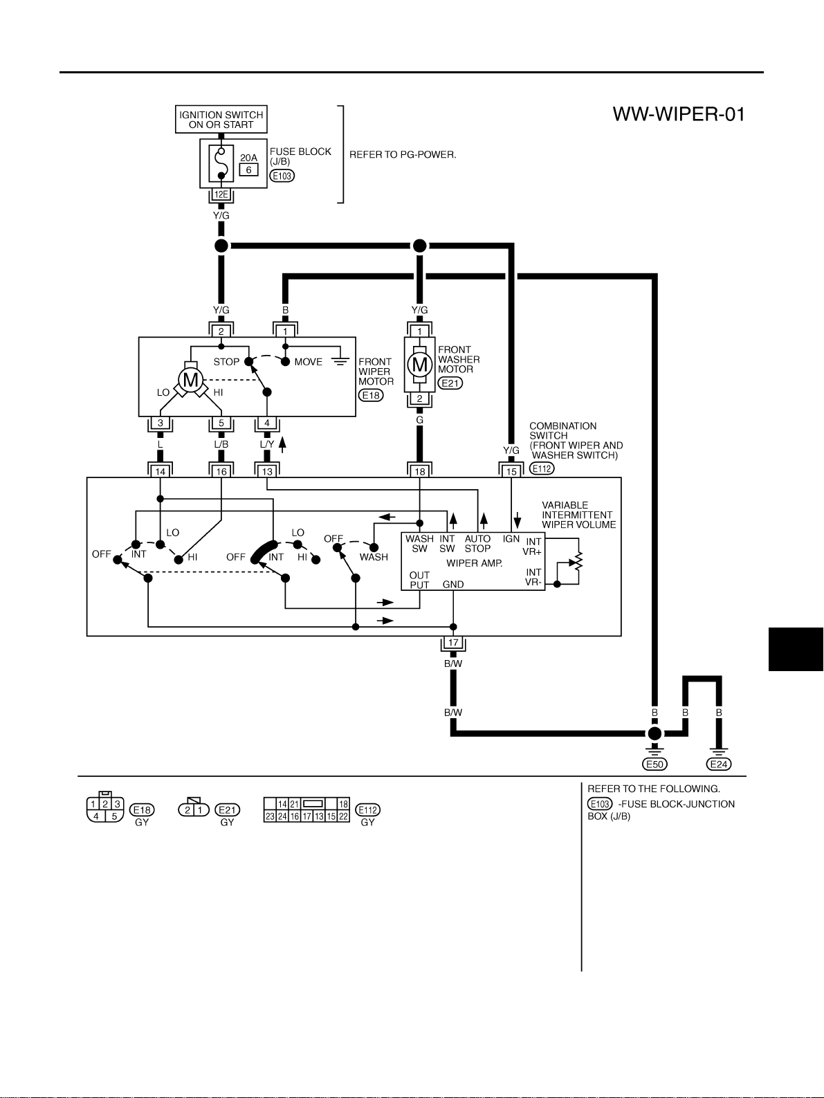
Wiring Diagram — WIPER — AKS00BBG
A
B
C
D
E
F
G
H
I
J
WW
L
M
TKWB0190E
Revision: 2006 July 2006 X-Trail
WW-5
FRONT WIPER AND WASHER SYSTEM
Terminal and Reference Values for Combination Switch AKS00BBH
Terminal
No.
13 L/Y
14 L
15 Y/G Ignition ON signal ON — Battery voltage
16 L/B
17 B/W Ground OFF — Approx. 0V
18 G
Wire
color
Item
Front wiper auto
stop signal
Front wiper motor
operation signal (LO)
Front wiper motor
operation signal (HI)
Front washer switch
signal
Ignition switch Condition or operation
ON
ON Wiper switch
ON Wiper switch
ON Washer switch
Condition
Wiper operating Approx. 0V
Wiper stopped Battery voltage
OFF Battery voltage
LO Approx. 0V
OFF Battery voltage
HI Approx. 0V
ON Approx. 0V
OFF Battery voltage
Voltage
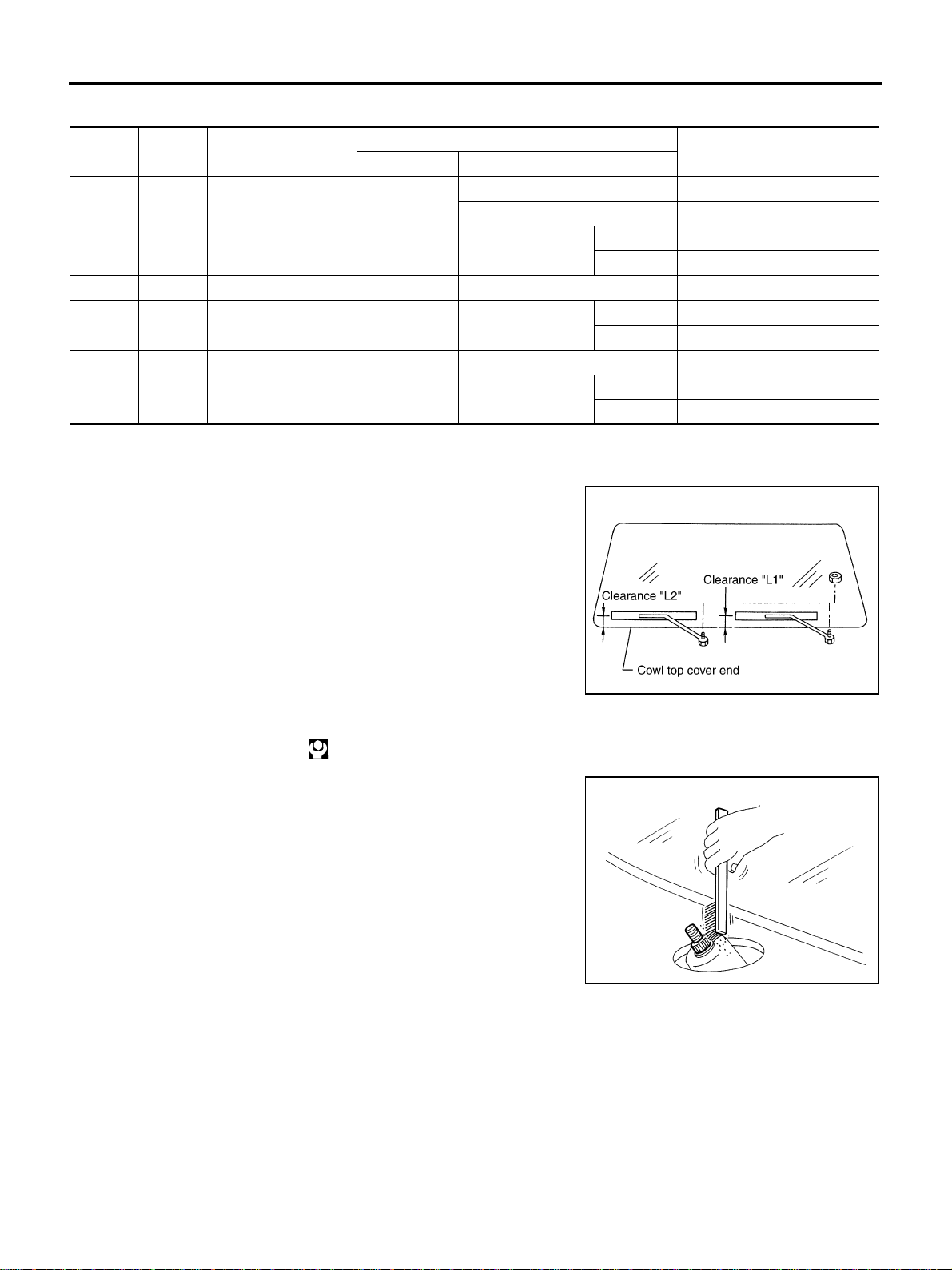
Removal and Installation of Front Wiper Arms, Adjustment of Wiper Arms Stop Location
1. Prior to wiper arm installation, turn on wiper switch to operate
wiper motor and then turn it “OFF” (Auto Stop).
2. Lift the blade up and then set it down onto glass surface to set
the blade center to clearance “L1” & “L2” immediately before
tightening nut.
3. Eject wash er fluid. Turn on wiper sw itch to operate wip er motor
and then turn it “OFF”.
4. Ensure that wiper blades st op within clearance “L1” & “L2” .
● Clearance “L1” : 49.2 - 64. 2 mm ( 1. 9 37 - 2 .52 8 i n )
● Clearance “L2” : 39.3 - 54. 3 mm ( 1. 5 47 - 2 .13 8 i n )
AKS00BBI
PKIA7843E
● Tighten wiper arm nuts to specified torque.
Front wiper arm nut : 23.6 N·m (2.4 kg-m, 17 ft-lb)
● Before reinstalling wiper arm, clean up the pivot area as illus-
trated. This will reduce po ssibility of w iper arm looseness.
SEL024J
Revision: 2006 July 2006 X-Trail
WW-6

FRONT WIPER AND WASHER SYSTEM
Removal and Installa tion of Wiper Motor and Linkage AKS00BBJ
SKIB3133E
*: In regard to the notation of torque in the illust ration, “NEW” s hows an ISO s tandard, “OLD” shows a conventional standard, and the
measurements of hexagon al width a cross flats are i n parenthes es. Fo r th e ide ntification in case of th e sam e width acr oss f lats, refe r to
Tightening Torque Table (New Standard Included)" .
GI-44, "
1. Rubber 2. Wiper frame 3. Wiper link
4. Motor arm 5. Wiper motor 6. Rubber
7. Wiper link
A
B
C
D
E
F
G
H
REMOVAL
1. Operate wiper motor, and stop it at the upper limit posi tion.
2. Remove wiper arm from the vehicle.
3. Remove cowl top cover. Refer to EI-19, "
COWL TOP" .
4. Remove screws (4) and re move wip er motor assembly from the
vehicle.
5. Disconnect wiper mo tor connector.
6. Remove wiper link from wiper frame.
7. Remove wiper motor from wiper frame.
PKIA8628E
INSTALLATION
1. Connect wiper motor to connector. Turn wiper switch ON to operate wiper motor, then turn wiper switch
OFF (auto stop).
2. Disconnect wiper motor connecto r.
3. Install wiper motor to wiper frame.
4. Install wiper motor assembly to the vehicle.
I
J
WW
L
M
Revision: 2006 July 2006 X-Trail
WW-7
Loading...