


 Loading...
C TRANSMISSION/TRANSAXLE
SECTION MT
MANUAL TRANSAXLE
CONTENTS
A
B
MT
D
E
PRECAUTIONS ......................................................... |
3 |
Service Notice or Precautions ................................. |
3 |
PREPARATION .......................................................... |
4 |
Special Service Tools .............................................. |
4 |
Commercial Service Tools ....................................... |
6 |
NOISE, VIBRATION AND HARSHNESS (NVH) |
|
TROUBLESHOOTING ............................................... |
8 |
NVH Troubleshooting Chart .................................... |
8 |
DESCRIPTION ........................................................... |
9 |
Cross-Sectional View .............................................. |
9 |
DOUBLE-CONE SYNCHRONIZER ................... |
10 |
TRIPLE-CONE SYNCHRONIZER ..................... |
10 |
REVERSE GEAR NOISE PREVENTION FUNC- |
|
TION (SYNCHRONIZING METHOD) ................ |
10 |
M/T OIL ..................................................................... |
11 |
Changing M/T Oil ................................................... |
11 |
DRAINING ........................................................... |
11 |
FILLING ............................................................... |
11 |
Checking M/T Oil .................................................... |
11 |
OIL LEAKAGE AND OIL LEVEL ......................... |
11 |
SIDE OIL SEAL ....................................................... |
12 |
Removal and Installation ....................................... |
12 |
REMOVAL .......................................................... |
12 |
INSTALLATION .................................................. |
12 |
POSITION SWITCH ................................................. |
13 |
Checking ............................................................... |
13 |
BACK-UP LAMP SWITCH ................................. |
13 |
PARK/NEUTRAL POSITION (PNP) SWITCH .... |
13 |
CONTROL LINKAGE .............................................. |
14 |
Components of Control Device and Cable ............ |
14 |
Removal and Installation ....................................... |
15 |
AIR BREATHER HOSE ........................................... |
16 |
Removal and Installation ....................................... |
16 |
TRANSAXLE ASSEMBLY ....................................... |
17 |
Removal and Installation ....................................... |
17 |
COMPONENTS ................................................. |
17 |
REMOVAL .......................................................... |
17 |
INSTALLATION .................................................. |
18 |
Disassembly and Assembly ................................... |
19 |
COMPONENTS .................................................. |
19 |
DISASSEMBLY .................................................. |
23 |
ASSEMBLY ........................................................ |
27 |
ADJUSTMENT ................................................... |
33 |
INPUT SHAFT AND GEARS ................................... |
37 |
Disassembly and Assembly ................................... |
37 |
DISASSEMBLY .................................................. |
37 |
INSPECTION AFTER DISASSEMBLY ............... |
38 |
ASSEMBLY ........................................................ |
41 |
MAINSHAFT AND GEARS ...................................... |
45 |
Disassembly and Assembly ................................... |
45 |
DISASSEMBLY .................................................. |
45 |
INSPECTION AFTER DISASSEMBLY ............... |
46 |
ASSEMBLY ........................................................ |
48 |
REVERSE IDLER SHAFT AND GEARS ................. |
53 |
Disassembly and Assembly ................................... |
53 |
DISASSEMBLY .................................................. |
53 |
INSPECTION AFTER DISASSEMBLY ............... |
53 |
ASSEMBLY ........................................................ |
54 |
FINAL DRIVE ........................................................... |
55 |
Disassembly and Assembly ................................... |
55 |
PRE-INSPECTION ............................................. |
55 |
DISASSEMBLY .................................................. |
55 |
INSPECTION AFTER DISASSEMBLY ............... |
56 |
ASSEMBLY ........................................................ |
56 |
SHIFT CONTROL .................................................... |
59 |
Inspection .............................................................. |
59 |
SHIFT FORK ...................................................... |
59 |
SERVICE DATA AND SPECIFICATIONS (SDS) ..... |
60 |
General Specifications ........................................... |
60 |
TRANSAXLE ...................................................... |
60 |
FINAL GEAR ...................................................... |
61 |
Gear End Play ....................................................... |
61 |
Baulk Ring Clearance ............................................ |
61 |
Available Snap Rings ............................................ |
61 |
INPUT SHAFT BEARING SPACER ................... |
61 |
5TH MAIN GEAR ............................................... |
62 |
Available C-Rings .................................................. |
62 |
F
G
H
I
J
K
L
M
Revision: 2006 July |
MT-1 |
2006 X-Trail |

MAINSHAFT C-RING ......................................... |
62 |
SHIM .................................................................... |
63 |
Available Thrust Washer ........................................ |
62 |
MAINSHAFT REAR BEARING ADJUSTING |
|
INPUT SHAFT THRUST WASHER .................... |
62 |
SHIM .................................................................... |
63 |
DIFFERENTIALSIDEGEARTHRUSTWASHER |
REVERSE IDLER GEAR ADJUSTING SHIM ..... |
64 |
|
|
... 62 |
Available Shims ..................................................... |
64 |
Available Adjusting Shims ..................................... |
63 |
BEARING PRELOAD .......................................... |
64 |
4TH MAIN GEAR ADJUSTING SHIM ................ |
63 |
DIFFERENTIAL SIDE BEARING ADJUSTING |
|
INPUT SHAFT REAR BEARING ADJUSTING |
|
SHIM(S) .............................................................. |
64 |
Revision: 2006 July |
MT-2 |
2006 X-Trail |

|
PRECAUTIONS |
|
|
PRECAUTIONS |
PFP:00001 |
Service Notice or Precautions |
ACS007XX |
● Do not reuse transaxle oil, once it has been drained.
● Check oil level or replace oil with vehicle on level surface.
● During removal or installation, keep inside of transaxle clear of dust or dirt.
● Check for the correct installation status prior to removal or disassembly. If matching marks are required, be certain they do not interfere with the function of the parts they are applied.
● In principle, tighten bolts or nuts gradually in several steps working diagonally from inside to outside. If tightening sequence is specified, use it.
● Be careful not to damage sliding surfaces and mating surfaces.
A
B
MT
D
E
F
G
H
I
J
K
L
M
Revision: 2006 July |
MT-3 |
2006 X-Trail |

|
PREPARATION |
|
|
PREPARATION |
PFP:00002 |
Special Service Tools |
ACS007XY |
The actual shapes of Kent-Moore tools may differ from those of special service tools illustrated here.
Tool number |
|
|||
(Kent-Moore No.) |
Description |
|||
Tool name |
|
|
||
|
|
|||
KV381054S0 |
● Removing differential side bearing outer |
|||
(J-34286) |
|
race |
||
Puller |
|
● Removing mainshaft front bearing |
||
|
|
|
||
|
|
|
ZZA0601D |
|
|
|
|||
ST35321000 |
● Installing input shaft oil seal |
|||
( |
— |
) |
● Installing reverse main gear |
|
Drift |
|
|
||
|
|
● Installing 1st main gear bushing |
||
a: 49 mm (1.93 in) dia. |
||||
|
||||
b: 41 mm (1.61 in) dia. |
● Installing 1st-2nd synchronizer hub |
|||
|
|
|
assembly |
|
|
|
|
● Installing 2nd main gear bushing |
|
|
|
|
● Installing 3rd main gear |
|
|
|
|
ZZA1000D |
|
|
|
|
● Removing differential side bearing (clutch |
|
|
|
|
housing side) |
|
|
|
|||
ST30720000 |
● Installing differential side oil seal |
|||
(J-25405) |
|
● Installing differential side bearing outer race |
||
Drift |
|
|
||
|
|
● Installing mainshaft rear bearing |
||
a: 77 mm (3.03 in) dia. |
||||
|
||||
b: 55.5 mm (2.185 in) dia. |
● Installing differential side bearing |
|||
|
|
|
ZZA0811D |
|
|
|
|||
ST33200000 |
● Installing mainshaft front bearing |
|||
(J-26082) |
|
● Installing 4th main gear |
||
Drift |
|
|
||
|
|
● Installing 5th main gear |
||
a: 60 mm (2.36 in) dia. |
||||
|
||||
b: 44.5 mm (1.752 in) dia. |
|
|||
|
|
|
ZZA1002D |
|
|
|
|||
KV40105320 |
Installing differential side bearing outer race |
|||
( |
— |
) |
|
|
Drift |
|
|
|
|
a: 88 mm (3.46 in) dia. |
|
|||
|
|
|
ZZA0898D |
|
|
|
|||
ST33061000 |
● Installing bore plug |
|||
(J-8107-2) |
|
● Removing differential side bearing |
||
Drift |
|
|
||
|
|
(transaxle case side) |
||
|
|
|
||
a:38 mm (1.50 in) dia.
b:28.5 mm (1.122 in) dia.
ZZA1000D
Revision: 2006 July |
MT-4 |
2006 X-Trail |

|
|
|
PREPARATION |
|
|
|
|
||
|
|
|
||
|
Tool number |
|
||
|
(Kent-Moore No.) |
Description |
||
|
Tool name |
|
|
|
|
|
|
||
|
ST33052000 |
● Installing welch plug |
||
( |
— |
) |
● Removing input shaft rear bearing |
|
|
Drift |
|
|
|
|
|
|
● Removing input shaft bearing spacer and |
|
|
a: 22 mm (0.87 in) dia. |
|||
|
5th stopper |
|||
|
b: 28 mm (1.10 in) dia. |
|||
|
|
|||
|
|
|
|
● Removing 5th input gear bushing, thrust |
|
|
|
|
washer, 4th input gear, 4th input gear |
|
|
|
|
bushing, 3rd-4th synchronizer hub |
|
|
|
|
assembly and 3rd input gear |
|
|
|
ZZA1023D |
● Installing input shaft front bearing |
|
|
|
|
● Removing mainshaft rear bearing |
|
|
|
|
● Removing 4th main gear and 5th main gear |
|
|
|
||
|
KV40105020 |
● Removing 5th input gear and 5th |
||
( |
— |
) |
synchronizer hub assembly |
|
|
Drift |
|
|
● Removing 3rd main gear, 2nd main gear, |
|
a: 39.7 mm (1.563 in) dia. |
|||
|
2nd main gear bushing, 1st-2nd |
|||
|
b: 35 mm (1.38 in) dia. |
|||
|
synchronizer hub assembly, 1st main gear, |
|||
|
c: 15 mm (0.59 in) |
|||
|
reverse main gear and 1st main gear |
|||
|
|
|
|
|
|
|
|
ZZA1133D |
bushing |
|
|
|
|
|
|
|
|
||
|
KV40105710 |
● Installing 3rd-4th synchronizer hub |
||
( |
— |
) |
assembly |
|
|
Press stand |
● Installing 4th input gear bushing |
||
|
a: 46 mm (1.81 in) dia. |
|||
|
● Installing 5th input gear bushing |
|||
|
b: 41 mm (1.61 in) |
|||
|
|
|||
|
|
|
|
● Installing 5th synchronizer hub assembly |
|
|
|
|
● Installing 2nd main gear bushing |
|
|
|
ZZA1058D |
● Installing 3rd main gear |
|
|
|
|
|
|
|
|
||
|
ST30032000 |
● Installing 5th stopper and input shaft |
||
|
(J-26010-01) |
bearing spacer |
||
|
Drift |
|
|
● Installing input shaft front bearing |
|
|
|
|
|
a:80 mm (3.15 in) dia.
b:38 mm (1.50 in) dia.
c:31 mm (1.22 in) dia.
|
|
|
ZZA0978D |
|
|
|
|||
ST38220000 |
● Installing reverse main gear |
|||
( |
— |
) |
● Installing 1st main gear bushing |
|
Press stand |
||||
● Installing 1st-2nd synchronizer hub |
||||
a: 63 mm (2.48 in) dia. |
||||
assembly |
||||
b: 65 mm (2.56 in) |
||||
|
||||
|
|
|
ZZA1058D |
|
|
|
|||
ST30901000 |
● Installing input shaft rear bearing |
|||
(J-26010-01) |
● Installing 4th main gear |
|||
Drift |
|
|
||
|
|
● Installing 5th main gear |
||
a: 79 mm (3.11 in) dia. |
||||
|
||||
b: 45 mm (1.77 in) dia. |
● Installing mainshaft rear bearing |
|||
c: 35.2 mm (1.386 in) dia. |
|
|||
|
|
|
ZZA0978D |
|
A
B
MT
D
E
F
G
H
I
J
K
L
M
Revision: 2006 July |
MT-5 |
2006 X-Trail |

|
PREPARATION |
|
|
|
|
|
|
|
Tool number |
|
|
(Kent-Moore No.) |
Description |
|
Tool name |
|
|
|
|
|
ST30031000 |
Measuring wear of inner baulk ring |
|
(J-22912-01) |
|
|
Puller |
|
|
|
ZZA0537D |
|
|
KV40101630 |
Installing reverse main gear |
(J-35870) |
|
Drift |
|
a:68 mm (2.68 in) dia.
b:60 mm (2.36 in) dia.
|
|
|
ZZA1003D |
|
|
|
|||
KV38102510 |
● Installing 1st main gear bushing |
|||
( |
— |
) |
● Installing 1st-2nd synchronizer hub |
|
Drift |
|
|
||
|
|
assembly |
||
a: 71 mm (2.80 in) dia. |
||||
● Installing differential side bearing (transaxle |
||||
b: 65 mm (2.56 in) dia. |
||||
case side) |
||||
|
|
|
||
|
|
|
ZZA0838D |
|
|
|
|||
KV40104830 |
Installing differential side bearing (clutch |
|||
( |
— |
) |
housing side) |
|
Drift |
|
|
|
|
a:70 mm (2.76 in) dia.
b:63.5 mm (2.500 in) dia.
|
ZZA0936D |
|
|
(J-39713) |
Measuring end play of side gear |
Preload adapter |
|
|
NT087 |
|
|
Commercial Service Tools |
ACS007XZ |
|
|
Tool name |
Description |
|
|
Puller |
Removing each bearing, gear and bushing |
|
ZZA0537D |
|
|
Puller |
Removing each bearing, gear and bushing |
NT077
Revision: 2006 July |
MT-6 |
2006 X-Trail |

|
|
PREPARATION |
||||
|
|
|
|
|
|
|
|
|
|
|
|
||
|
Tool name |
|
Description |
|||
|
|
|
|
|
|
A |
|
Pin punch |
|
Removing and installing each retaining pin |
|||
|
Tip diameter: 4.5 mm (0.177 in) dia. |
|
|
|
|
|
|
|
|
|
|
|
B |
|
|
|
|
|
|
|
|
|
ZZA0815D |
|
|
|
MT |
|
|
|
|
|
||
|
|
|
|
|
|
|
|
Power tool |
|
Loosening bolts and nuts |
D |
||
|
|
|
|
|
|
|
|
|
|
|
|
|
E |
|
|
PBIC0190E |
|
|
||
|
|
|
|
|
|
F |
|
|
|
|
|
|
|
|
|
|
|
|
|
G |
|
|
|
|
|
|
H |
|
|
|
|
|
|
I |
|
|
|
|
|
|
J |
|
|
|
|
|
|
K |
|
|
|
|
|
|
L |
|
|
|
|
|
|
M |
Revision: 2006 July |
MT-7 |
2006 X-Trail |

NOISE, VIBRATION AND HARSHNESS (NVH) TROUBLESHOOTING
NOISE, VIBRATION AND HARSHNESS (NVH) TROUBLESHOOTING
NVH Troubleshooting Chart
PFP:00003
ACS007Y0
Use the chart below to help you find the cause of the symptom. The numbers indicate the order of the inspection. If necessary, repair or replace these parts.
Reference page |
|
MA-19 |
|
|
MT-19 |
|
MT-19 |
|
MT-22 |
|
MT-14 |
|
MT-22 |
|
MT-22 |
|
MT-20 |
|
MT-20 |
|
MT-20 |
|
MT-20 |
|
|
|
|
|
|
|
|
|
|
|
|
|
|
|
|||||||||||||
|
|
|
|
|
|
|
|
|
|
|
|
|
|
|
|||||||||||
|
|
|
|
|
|
|
|
|
|
|
|
|
|
|
|
|
|
|
|
|
|
|
|
|
|
|
|
|
|
|
|
|
|
|
|
|
|
|
|
CHECK BALL (Worn or damaged) |
|
|
|
|
|
|
|
|
|
|
|
SUSPECTED PARTS |
|
|
|
|
|
|
|
|
|
|
|
|
CHECK PLUG RETURN SPRING AND |
|
|
|
|
|
|
|
|
|
|
||
(Possible cause) |
|
|
|
|
|
|
|
|
|
|
SHIFT CONTROL LINKAGE (Worn) |
|
|
|
|
|
|
|
|
|
|
||||
|
|
OIL (Oil level is low.) |
OIL (Wrong oil.) |
OIL (Oil level is high.) |
GASKET (Damaged) |
OIL SEAL (Worn or damaged) |
O-RING (Worn or damaged) |
SHIFT FORK (Worn) |
GEAR (Worn or damaged) |
BEARING (Worn or damaged) |
BAULK RING (Worn or damaged) |
INSERT SPRING (Damaged) |
|||||||||||||
|
|
|
|
|
|
|
|
|
|
|
|
|
|
|
|
|
|
|
|
|
|
|
|||
|
Noise |
1 |
2 |
|
|
|
|
|
|
|
|
|
|
|
|
|
3 |
3 |
|
|
|
|
|||
|
|
|
|
|
|
|
|
|
|
|
|
|
|
|
|
|
|
|
|
|
|
||||
Symptoms |
Oil leakage |
|
3 |
1 |
2 |
2 |
2 |
|
|
|
|
|
|
|
|
|
|
|
|
|
|
||||
|
|
|
|
|
|
|
|
|
|
|
|
|
|
|
|
|
|
|
|
|
|
|
|
|
|
Hard to shift or will not shift |
|
1 |
1 |
|
|
|
|
|
|
2 |
|
|
|
|
|
|
|
|
3 |
3 |
|||||
|
|
|
|
|
|
|
|
|
|
|
|
|
|
|
|
||||||||||
|
|
|
|
|
|
|
|
|
|
|
|
|
|
|
|
|
|
|
|
|
|
||||
|
Jumps out of gear |
|
|
|
|
|
|
|
|
|
|
1 |
2 |
3 |
3 |
|
|
|
|
|
|
||||
|
|
|
|
|
|
|
|
|
|
|
|
|
|
|
|
|
|
|
|
|
|
|
|
|
|
Revision: 2006 July |
MT-8 |
2006 X-Trail |

|
|
|
|
DESCRIPTION |
|
|
|
|
|
|
|
|
|
|
|
|
|
|
|
DESCRIPTION |
|
|
|
PFP:00000 |
|
A |
|||
Cross-Sectional View |
|
|
|
|
|
|
|||
|
|
|
ACS007Y1 |
|
|
||||
|
|
|
|
|
|
|
|
|
B |
|
|
|
|
|
|
|
|
|
|
|
|
|
|
|
|
|
|
|
|
|
|
|
|
|
|
|
|
|
MT |
|
|
|
|
|
|
|
|
|
|
|
|
|
|
|
|
|
|
|
D |
|
|
|
|
|
|
|
|
|
E |
|
|
|
|
|
|
|
|
|
F |
|
|
|
|
|
|
|
|
|
G |
|
|
|
|
|
|
|
|
|
H |
|
|
|
|
|
|
|
|
|
I |
|
|
|
|
|
|
|
|
|
J |
|
|
|
|
|
|
|
|
|
K |
|
|
|
|
|
|
|
|
|
L |
|
|
|
|
|
|
PCIB0910E |
|
|
M |
|
|
|
|
|
|
|
|
|
|
1. |
3rd input gear |
2. |
3rd-4th synchronizer hub |
3. |
3rd-4th coupling sleeve |
|
|
||
4. |
4th input gear |
5. |
5th input gear |
6. |
5th synchronizer hub |
|
|
||
7. |
5th coupling sleeve |
8. |
Input shaft rear bearing |
9. |
Mainshaft rear bearing |
|
|
||
10. |
5th main gear |
11. |
4th main gear |
12. |
3rd main gear |
|
|
||
13. |
2nd main gear |
14. |
1st-2nd coupling sleeve |
15. |
1st-2nd synchronizer hub |
|
|
||
16. |
1st main gear |
17. |
Reverse main gear |
18. |
Differential side bearing |
|
|
||
19. |
Differential case |
20. |
Final gear |
21. |
Differential side bearing |
|
|
||
22. |
Mainshaft front bearing |
23. |
Mainshaft |
24. |
Input shaft |
|
|
||
25. |
Input shaft front bearing |
26. |
Clutch housing |
27. |
Reverse idler shaft |
|
|
||
28. |
Reverse idler gear (Front) |
29. |
Reverse coupling sleeve |
30. |
Reverse synchronizer hub |
|
|
||
31. |
Reverse idler gear (Rear) |
|
|
|
|
|
|
|
|
Revision: 2006 July |
MT-9 |
2006 X-Trail |
DESCRIPTION
DOUBLE-CONE SYNCHRONIZER
Double-cone synchronizer is adopted for 3rd gear to reduce operating force of the shift lever.
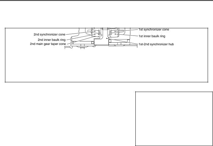
TRIPLE-CONE SYNCHRONIZER
Triple-cone synchronizer is adopted for 1st and 2nd gears to reduce operating force of the shift lever.
PCIB1454E
REVERSE GEAR NOISE PREVENTION FUNCTION (SYNCHRONIZING METHOD)
Reverse gear can be matched smoothly in a structure by setting synchronizer hub, coupling sleeve, baulk ring and insert spring to reverse gear, and letting reverse gear be synchronized.
PCIB0775E
Revision: 2006 July |
MT-10 |
2006 X-Trail |
M/T OIL
M/T OIL |
PFP:KLD20 |
|
Changing M/T Oil |
ACS007Y2 |
|
DRAINING |
|
|
1. |
Start engine and let it run to warm up transaxle. |
|
2. |
Stop engine. Remove drain plug and drain oil. |
|
3. |
Set a gasket on drain plug and install it to transaxle, and tighten to the specified torque. Refer to MT-19, |
|
|
"Case and Housing Components" . |
|
CAUTION:
Do not reuse gasket.
A
B
MT
FILLING
1.Remove filler plug. Fill with new oil to transaxle.
Oil grade and viscosity:
Refer to MA-10, "Fluids and Lubricants" . Oil capacity (reference):
Model code number EQ008:
Approx. 2.2 (4-5/8 US pt, 3-7/8 Imp pt) Model code number EQ00C:
Approx. 2.0 (4-1/4 US pt, 3-1/2 lmp pt)
D
E
F
G
PCIB1618E
2.After refilling oil, check oil level.
3.Set a gasket on filler plug and then install it to clutch housing. Tighten filler plug to the specified torque. H Refer to MT-19, "Case and Housing Components" .
CAUTION: |
|
Do not reuse gasket. |
I |
|
|
Checking M/T Oil |
ACS007Y3 |
OIL LEAKAGE AND OIL LEVEL
●Make sure that oil is not leaking from transaxle or around it.
●Remove filler plug.
●Measure oil level using a suitable gauge as shown in the figure, and then check if it is within the specifications.
Oil level “L”: |
|
Model code number EQ008: |
|
168.0 - 174.0 mm (6.61 - 6.85 in) |
|
Model code number EQ00C: |
|
174.0 - 180.0 mm (6.85 - 7.09 in) |
|
CAUTION: |
|
Do not start engine while checking oil level. |
PCIB1478E |
●Set a gasket on filler plug and then install it to transaxle. Tighten
filler plug to the specified torque. Refer to MT-19, "Case and Housing Components" .
CAUTION:
Do not reuse gasket.
J
K
L
M
Revision: 2006 July |
MT-11 |
2006 X-Trail |

SIDE OIL SEAL
SIDE OIL SEAL
Removal and Installation
REMOVAL
PFP:32113
ACS007Y4
●Clutch housing side oil seal used on AWD vehicles is attached to transfer. Be sure to replace it when transfer is removed.
1.Remove drive shaft from transaxle. Refer to FAX-13, "FRONT DRIVE SHAFT" .
2.Remove oil seal with a flat-bladed screwdriver.
CAUTION:
Be careful not to damage the case surface when removing oil seal.
SCIA0824E
INSTALLATION
1.Using the drift, drive the oil seal straight until it protrudes from the case end equal to the dimension A shown in the figure.
Dimension “A”:
Within 0.5 mm (0.020 in) of flush with the case.
Drift to be used |
|
Transaxle case side |
: ST30720000 (J-25405) |
Clutch housing side |
: ST30720000 (J-25405) |
CAUTION:
● Apply multi-purpose grease onto oil seal lip. (For clutch SCIA0352E housing side)
● Do not reuse oil seal.
2.Install all parts in the reverse order of removal and check oil level after installation. Refer to MT-11, "Checking M/T Oil" .
Revision: 2006 July |
MT-12 |
2006 X-Trail |

|
POSITION SWITCH |
POSITION SWITCH |
|
Checking |
|
BACK-UP LAMP SWITCH |
|
● Check continuity. |
|
|
|
Gear position |
Continuity |
|
|
Reverse |
Yes |
|
|
Except reverse |
No |
|
|
PARK/NEUTRAL POSITION (PNP) SWITCH
●Check continuity.
Gear position |
Continuity |
|
|
Neutral |
Yes |
|
|
Except neutral |
No |
|
|
PFP:32005
A
ACS007Y5
B
MT
D
SCIA5644E E
F
G
H
I
J
K
L
M
Revision: 2006 July |
MT-13 |
2006 X-Trail |
CONTROL LINKAGE
CONTROL LINKAGE
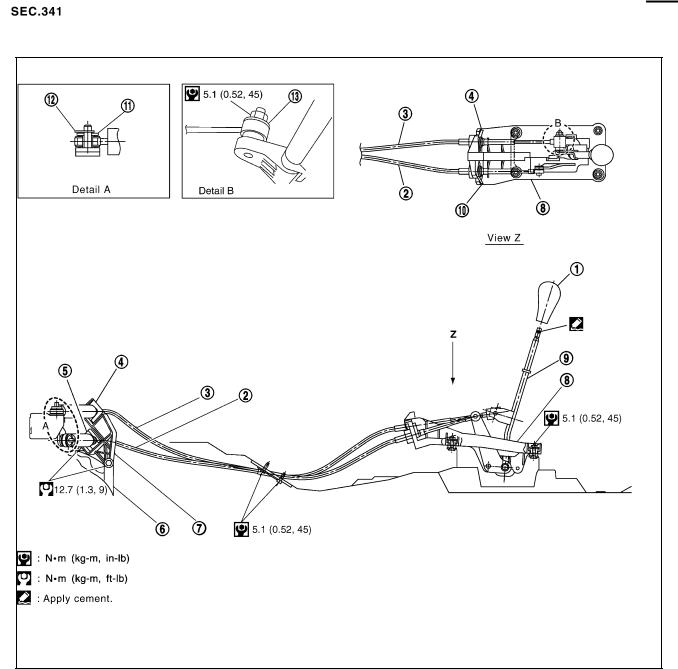
Components of Control Device and Cable
PFP:34103
ACS007Y6
PCIB0911E
1. |
Control lever knob |
2. |
Select cable |
3. |
Shift cable |
4. |
Lock plate (shift side) |
5. |
Lock plate (select side) |
6. |
Clutch housing |
7. |
Cable mounting bracket |
8. |
Control device assembly |
9. |
Control lever |
10. |
Lock plate |
11. |
Washer |
12. |
Snap pin |
13. |
Washer |
|
|
|
|
Revision: 2006 July |
MT-14 |
2006 X-Trail |

CONTROL LINKAGE
Removal and Installation |
ACS007Y7 |
Note the following, when removal and installation.
●Shift the control lever to the neutral position for removal.
●Keep in mind that the select side lock plate for securing control cable is different from the shift side lock plate.
●After assembly, make sure selector lever automatically returns to Neutral when it is moved to 1st-2nd or Reverse.
A
B
MT
D
E
F
G
H
I
J
K
L
M
Revision: 2006 July |
MT-15 |
2006 X-Trail |

|
AIR BREATHER HOSE |
|
|
AIR BREATHER HOSE |
PFP:31098 |
Removal and Installation |
ACS007Y8 |
Refer to the figure for air breather hose removal and installation information.
PCIB0778E
1. |
Air cleaner case |
2. |
Transaxle |
3. |
Clip |
4. |
Air breather hose |
5. |
Clip |
6. |
PCV hose |
7.Resonator
CAUTION:
●Make sure there are no pinched or restricted areas on air breather hose caused by bending or winding when installing it.
●Be sure to insert air breather hose into air breather tube until overlap area reaches the spool.
Revision: 2006 July |
MT-16 |
2006 X-Trail |

TRANSAXLE ASSEMBLY
TRANSAXLE ASSEMBLY |
PFP:32010 |
Removal and Installation |
ACS007Y9 |
COMPONENTS |
|
|
|
|
|
|
PCIB0912E |
1. |
Center member |
2. |
Front engine mounting insulator |
3. |
Grommet |
4. |
Transaxle assembly |
5. |
Rear engine mounting bracket |
6. |
Rear engine mounting insulator |
7. |
LH engine mounting insulator |
8. |
Stopper |
9. |
LH engine mounting bracket |
REMOVAL
A
B
MT
D
E
F
G
H
I
J
K
1.Remove air cleaner, air duct and battery. Refer to EM-14, "Removal and Installation" .
2.Remove air breather hose. Refer to MT-16, "Removal and Installation" .
3.Remove clutch operating cylinder. Refer to CL-10, "Removal and Installation" .
CAUTION:
Do not depress clutch pedal during removal procedure.
4.Disconnect control cable from transaxle assembly. Refer to MT-15, "Removal and Installation" .
5.Drain gear oil. Refer to MT-11, "Changing M/T Oil" .
6.Disconnect park/neutral position switch, back-up lamp switch and ground harness connectors.
7.Remove exhaust front tube. Refer to EX-3, "Removal and Installation" .
8.Remove drive shaft. Refer to FAX-13, "FRONT DRIVE SHAFT" .
9.Remove transfer with power tool. Refer to TF-48, "Removal and Installation" .
10.Remove starter motor with power tool. Refer to SC-16, "Removal and Installation" .
11.Support transaxle assembly with a jack.
CAUTION:
When setting a jack, be careful not to bring it into contact with switches.
12.Remove center member, engine insulator and engine mount bracket with power tool. Refer to EM-78, "Removal and Installation (AWD Models)" .
13.Remove suspension members with power tool. Refer to FSU-17, "Removal and Installation" .
14.Support engine with a jack under oil pan.
L
M
Revision: 2006 July |
MT-17 |
2006 X-Trail |

TRANSAXLE ASSEMBLY
15.Remove bolts fixing transaxle assembly to engine with power tool.
16.Remove transaxle assembly from vehicle.
CAUTION:
Secure transaxle assembly to a jack while removing it.
MTD0062D
INSTALLATION
Note the following, and install in the reverse order of removal.
●When installing the transaxle assembly to the engine, install the mounting bolts following the standard below.
CAUTION:
When installing transaxle assembly, be careful not to bring transaxle input shaft into contact with clutch cover.
Bolt No. |
1 |
2 |
3 |
4 |
|
5 |
6 |
|
|
|
|
|
|
|
|
|
|
|
|
Quantity |
2 |
1 |
1 |
2 |
|
2 |
2 |
|
|
|
|
|
|
|
|
|
|
|
|
Bolt length “ ” |
40 |
75 |
45 |
40 |
|
30 |
40 |
|
|
mm (in) |
(1.57) |
(2.95) |
(1.77) |
(1.57) |
|
(1.18) |
(1.57) |
|
|
|
|
|
|
|
|
|
|
|
SCIA0353E |
Tightening torque |
|
74.5 |
|
|
42.7 |
35.3 |
|||
|
|
|
|
|
|||||
N·m (kg-m, ft-lb) |
|
(7.6, 55) |
|
(4.4, 31) |
(3.6, 26) |
|
|
||
|
|
|
|
|
|
|
|
|
|
●After installation, check oil level and check for leaks and loose mechanisms. Refer to MT-11, "Checking M/ T Oil" .
Revision: 2006 July |
MT-18 |
2006 X-Trail |

TRANSAXLE ASSEMBLY
Disassembly and Assembly |
ACS008HV |
|||
COMPONENTS |
|
|
A |
|
Case and Housing Components |
|
|
|
|
|
|
|
|
B |
|
|
|
|
|
|
|
|
|
|
|
|
|
|
MT |
|
|
|
|
|
|
|
|
|
D |
|
|
|
|
E |
|
|
|
|
F |
|
|
|
|
G |
|
|
|
|
H |
|
|
|
|
I |
|
|
|
|
J |
|
|
|
|
K |
|
|
|
|
L |
|
|
|
|
M |
PCIB1619E
1. |
Clutch housing |
2. |
Differential side oil seal |
3. |
Ball pin |
4. |
Washer |
5. |
Input shaft oil seal |
6. |
Oil channel |
7. |
Magnet |
8. |
Gasket |
9. |
Filler plug |
10. |
Back-up lamp switch |
11. |
Oil gutter |
12. |
Baffle plate |
13. |
Transaxle case |
14. |
Plug |
15. |
Welch plug |
16. |
Bore plug |
17. |
Drain plug |
18. |
Differential side oil seal |
19. |
Park/Neutral position (PNP) switch |
20. |
Air breather tube |
|
|
Revision: 2006 July |
MT-19 |
2006 X-Trail |

TRANSAXLE ASSEMBLY
Gear Components
PCIB1458E
1. |
Input shaft front bearing |
2. |
Input shaft |
3. |
3rd needle bearing |
4. |
3rd input gear |
5. |
3rd inner baulk ring |
6. |
3rd synchronizer cone |
7. |
3rd outer baulk ring |
8. |
3rd-4th spread spring |
9. |
3rd-4th shifting insert |
10. |
3rd-4th synchronizer hub |
11. |
4th baulk ring |
12. |
3rd-4th coupling sleeve |
13. |
4th input gear bushing |
14. |
4th needle bearing |
15. |
4th input gear |
16. |
Thrust washer |
17. |
5th input gear bushing |
18. |
5th needle bearing |
19. |
5th input gear |
20. |
5th baulk ring |
21. |
5th spread spring |
22. |
5th shifting insert |
23. |
5th synchronizer hub |
24. |
5th coupling sleeve |
25. |
5th stopper |
26. |
Input shaft bearing spacer |
27. |
Snap ring |
28. |
Input shaft rear bearing |
29. |
Oil channel |
30. |
Input shaft rear bearing adjusting |
|
|
|
|
|
shim |
31. |
Retaining pin |
32. |
Reverse idler shaft |
33. |
Thrust needle bearing |
34. |
Reverse idler gear needle bearing |
35. |
Reverse insert spring |
36. |
Reverse idler gear (Front) |
37. |
Reverse baulk ring |
38. |
Reverse coupling sleeve |
39. |
Reverse idler gear (Rear) |
40 |
Reverse idler gear adjusting shim |
|
|
|
|
Revision: 2006 July |
MT-20 |
2006 X-Trail |
Loading...