


 Loading...
G STEERING
SECTION PS
POWER STEERING SYSTEM
A
B
C
D
CONTENTS
E
PRECAUTIONS ......................................................... |
3 |
Precautions for Supplemental Restraint System |
|
(SRS) “AIR BAG” and “SEAT BELT PRE-TEN- |
|
SIONER” ................................................................. |
3 |
Precautions for Steering System ............................. |
3 |
PREPARATION .......................................................... |
4 |
Special Service Tools .............................................. |
4 |
Commercial Service Tools ....................................... |
5 |
NOISE, VIBRATION AND HARSHNESS (NVH) |
|
TROUBLESHOOTING ............................................... |
6 |
NVH Trouble Shooting Chart ................................... |
6 |
POWER STEERING FLUID ....................................... |
7 |
Checking Fluid Level ............................................... |
7 |
Checking Fluid Leakage .......................................... |
7 |
Air Bleeding Hydraulic System ................................ |
7 |
STEERING WHEEL ................................................... |
9 |
On-Vehicle Inspection and Service ......................... |
9 |
CHECKING CONDITION OF INSTALLATION ..... |
9 |
CHECKING STEERING WHEEL PLAY ............... |
9 |
CHECKING NEUTRAL POSITION STEERING |
|
WHEEL ................................................................ |
9 |
CHECKING STEERING WHEEL TURNING |
|
FORCE ................................................................. |
9 |
CHECKING FRONT WHEEL TURNING ANGLE... 10 |
|
Removal and Installation ....................................... |
10 |
REMOVAL .......................................................... |
10 |
INSTALLATION ................................................... |
11 |
STEERING COLUMN .............................................. |
12 |
Removal and Installation ....................................... |
12 |
COMPONENTS ................................................. |
12 |
REMOVAL OF LOWER SHAFT, HOLE COVER, |
|
CLAMP AND HOLE COVER SEAL ................... |
12 |
INSTALLATION OF LOWER SHAFT, HOLE |
|
COVER, CLAMP AND HOLE COVER SEAL ..... |
13 |
REMOVAL OF STEERING COLUMN ASSEM- |
|
BLY ..................................................................... |
13 |
INSPECTION AFTER REMOVAL ...................... |
14 |
INSTALLATION OF STEERING COLUMN |
|
ASSEMBLY ........................................................ |
14 |
INSPECTION AFTER INSTALLATION ............... |
14 |
Disassembly and Assembly ................................... |
15 |
COMPONENT .................................................... |
15 |
DISASSEMBLY .................................................. |
15 |
INSPECTION AFTER DISASSEMBLY ............... |
15 |
ASSEMBLY ........................................................ |
15 |
INSPECTION AFTER ASSEMBLY ..................... |
16 |
POWER STEERING GEAR AND LINKAGE ........... |
17 |
Removal and Installation ....................................... |
17 |
COMPONENT .................................................... |
17 |
REMOVAL .......................................................... |
17 |
INSTALLATION .................................................. |
18 |
INSPECTION AFTER INSTALLATION ............... |
18 |
Disassembly and Assembly ................................... |
19 |
COMPONENT .................................................... |
19 |
DISASSEMBLY .................................................. |
20 |
INSPECTION AFTER DISASSEMBLY ............... |
22 |
ASSEMBLY ........................................................ |
23 |
POWER STEERING OIL PUMP .............................. |
28 |
On-Vehicle Inspection and Service ........................ |
28 |
CHECKING RELIEF OIL PRESSURE ............... |
28 |
Removal and Installation ....................................... |
28 |
REMOVAL .......................................................... |
28 |
INSTALLATION .................................................. |
28 |
Disassembly and Assembly ................................... |
29 |
COMPONENT .................................................... |
29 |
INSPECTION BEFORE DISASSEMBLY ............ |
29 |
DISASSEMBLY .................................................. |
29 |
INSPECTION AFTER DISASSEMBLY ............... |
30 |
ASSEMBLY ........................................................ |
30 |
HYDRAULIC LINE ................................................... |
33 |
Component ............................................................ |
33 |
Removal and Installation ....................................... |
34 |
SERVICE DATA AND SPECIFICATIONS (SDS) ..... |
35 |
Steering Wheel ...................................................... |
35 |
Steering Angle ....................................................... |
35 |
Steering Column .................................................... |
35 |
Steering Outer Socket and Inner Socket ............... |
35 |
Steering Gear ........................................................ |
36 |
F
PS
H
I
J
K
L
M
Revision: 2006 July |
PS-1 |
2006 X-Trail |

Oil Pump ................................................................ |
36 |
Steering Fluid ......................................................... |
36 |
Revision: 2006 July |
PS-2 |
2006 X-Trail |

|
PRECAUTIONS |
|
|
|
|
|
|
PRECAUTIONS |
PFP:00001 |
A |
|
Precautions for Supplemental Restraint System (SRS) “AIR BAG” and “SEAT |
|||
|
|||
BELT PRE-TENSIONER” |
AGS000L9 |
|
|
The Supplemental Restraint System such as “AIR BAG” and “SEAT BELT PRE-TENSIONER”, used along B |
||
with a front seat belt, helps to reduce the risk or severity of injury to the driver and front passenger for certain |
|
|
types of collision. Information necessary to service the system safely is included in the SRS and SB section of |
|
|
this Service Manual. |
C |
|
WARNING: |
||
|
||
●To avoid rendering the SRS inoperative, which could increase the risk of personal injury or death in the event of a collision which would result in air bag inflation, all maintenance must be per-
formed by an authorized NISSAN/INFINITI dealer.
●Improper maintenance, including incorrect removal and installation of the SRS, can lead to personal injury caused by unintentional activation of the system. For removal of Spiral Cable and Air
Bag Module, see the SRS section.
●Do not use electrical test equipment on any circuit related to the SRS unless instructed to in this Service Manual. SRS wiring harnesses can be identified by yellow and/or orange harnesses or
harness connectors.
Precautions for Steering System |
AGS000LA |
D
E
F
●In case of removing steering gear, make the final tightening with grounded and unloaded vehicle condi- PS tion, and then check wheel alignment.
●Observe the following precautions when disassembling.
– |
Before disassembly, thoroughly clean the outside of the unit. |
H |
–Disassembly should be done in a clean work area. It is important to prevent the internal parts from becoming contaminated by dirt or other foreign matter.
– For easier and proper assembly, place disassembled parts in order on a parts rack.
– Use nylon cloth or paper towels to clean the parts; common shop rags can leave lint that might interfere with their operation.
– Do not reuse non-reusable parts.
– Before assembling, apply the specified grease to the directed parts.
I
J
K
L
M
Revision: 2006 July |
PS-3 |
2006 X-Trail |
PREPARATION
PREPARATION
Special Service Tools
PFP:00002
AGS000K8
Tool number |
|
(Kent-Moore No.) |
Description |
Tool name |
|
|
|
ST27180001 |
Removing steering wheel |
(J-25726-A) |
|
Steering wheel puller |
|
|
S-NT544 |
|
|
HT72520000 |
Removing steering outer socket |
(J-25730-A) |
|
Ball joint remover |
|
a:33 mm (1.30 in)
b:50 mm (1.97 in)
r: 11.5 mm (0.453 in)
|
NT546 |
|
|
ST3127S000 |
Inspecting sliding torque, steering torque, and |
(J-25765-A) |
rotating torque for ball joint |
Preload gauge |
|
|
|
|
ZZA0806D |
|
|
||
KV48104400 |
Installing rack Teflon ring |
||
( |
— |
) |
|
Teflon ring correcting tool |
|
||
a: 50 mm (1.97 in) dia. |
|
||
b: 36 mm (1.42 in) dia. |
|
||
c: 100 mm (3.94 in) |
|
||
|
|
|
S-NT550 |
|
|
||
KV48103400 |
Inspecting rotating torque |
||
( |
— |
) |
|
Torque adapter |
|
||
|
ZZA0824D |
|
|
KV48103500 |
Measuring oil pump relief pressure |
(J-26357) |
|
Pressure gauge |
|
S-NT547
Revision: 2006 July |
PS-4 |
2006 X-Trail |

PREPARATION
Tool number |
|
|
|
|
A |
(Kent-Moore No.) |
|
Description |
|
|
|
Tool name |
|
|
|
|
|
|
|
|
|
|
|
KV48102500 |
|
Measuring oil pump relief pressure |
|
|
B |
(J-33914) |
|
|
|
|
|
Pressure gauge adapter |
|
|
|
|
|
|
|
|
|
|
C |
|
S-NT542 |
|
|
|
|
|
|
|
|
|
D |
ST35300000 |
|
Installing oil seal |
|
|
|
( — ) |
|
|
|
|
|
Drift |
|
|
|
|
|
a: 45.1 mm (1.776 in) dia. |
|
|
|
|
E |
b: 59.0 mm (2.323 in) dia. |
|
|
|
|
|
|
ZZA0881D |
|
|
|
F |
|
|
|
|
|
|
Commercial Service Tools |
|
|
|
|
|
|
|
AGS000K9 |
|||
|
|
|
|
|
|
|
|
|
|
|
|
Tool number |
|
Description |
|
|
PS |
Tool name |
|
|
|
||
|
|
|
|
|
|
|
|
|
|
|
|
|
|
|
|
|
|
Power tool |
|
Loosening bolts and nuts |
|
|
|
|
|
|
|
|
H |
|
|
|
|
|
I |
|
PBIC0190E |
|
|
|
|
|
|
|
|
|
J |
|
|
|
|
|
|
|
|
|
|
|
K |
|
|
|
|
|
L |
|
|
|
|
|
M |
Revision: 2006 July |
PS-5 |
2006 X-Trail |

NOISE, VIBRATION AND HARSHNESS (NVH) TROUBLESHOOTING
NOISE, VIBRATION AND HARSHNESS (NVH) TROUBLESHOOTING
NVH Trouble Shooting Chart
PFP:00003
AGS000KA
Use chart below to help you find the cause of the symptom. If necessary, repair or replace these parts.
Reference page |
|
PS-7 |
|
PS-7 |
|
PS-22 |
|
PS-22 |
|
PS-22 |
|
PS-7 |
|
PS-9 |
|
PS-9 |
|
EM-11 |
|
PS-9 |
|
PS-15 |
|
PS-17 |
|
PS-14 |
|
PS-12 |
|
PS-17 |
|
PRinNVHsection |
RFDinNVHsection |
|
RAX,FAX,inFSU, RSU section |
WTinNVHsection |
WTinNVHsection |
FAX,inNVHRAX section |
BRinNVHsection |
|
|
|
|
|
|
|
|
|
|
|
|
|
|
|
|
|
|||||||||||||||||||||||||
|
|
|
|
|
|
|
|
|
|
|
|
|
|
|
|
|
|
|
|
|
|
|
|
|
|
|
|
|
|
|
|
|
|
|
|
|
|
|
||
|
|
|
|
|
|
|
|
|
|
|
|
|
|
|
|
|
|
|
|
|
|
|
|
|
|
|
|
|
|
|
|
|
|
|
|
NVH |
|
|
|
|
|
|
|
|
|
|
|
|
|
|
|
|
|
|
|
|
|
|
|
|
|
|
|
|
|
|
|
|
|
|
|
|
|
|
|
|
|
|
|
|
|
|
|
|
|
|
|
|
|
|
|
|
|
|
|
|
|
|
|
|
|
|
|
|
|
|
|
|
|
|
|
|
|
|
|
|
|
|
|
|
||
Possible cause and suspected parts |
levelFluid |
|
systemhydraulicinAir |
|
swingingjointballsocketOuter force |
|
rotatingjointballsocketOutertorque |
|
endjointballsocketOuterplay |
leakagefluidSteering |
|
playwheelSteering |
|
slidingrackgearSteeringforce |
|
loosenessbeltDrive |
|
wheelsteeringImproper |
|
loosenessorinstallationImproperor tilt lock lever |
|
deteriorationrubberMounting |
|
deformationcolumnSteeringor damage |
|
loosenessorinstallationImproperof steering column |
|
loosenesslinkageSteering |
SHAFTPROPELLER |
DIFFERENTIAL |
|
SUSPENSIONandAXLE |
TIRES |
WHEELSROAD |
SHAFTDRIVE |
BRAKES |
||||
|
|
|
|
|
|
|
|
|
|
|
|
|
|
|
|
|
|
|
|
|
|
|
|
|
|
|
|
|
|
|
|
|
|
|
|
|
|
|||
|
|
|
|
|
|
|
|
|
|
|
|
|
|
|
|
|
|
|
|
|
|
|
|
|
|
|
|
|
|
|
|
|
|
|
|
|
|
|
||
|
|
Noise |
× |
|
× |
|
× |
× |
× |
× |
× |
|
× |
|
× |
|
|
|
|
|
|
|
|
|
|
|
|
|
× × |
× |
× |
|
× |
× |
× |
|
|
|||
|
|
|
|
|
|
|
|
|
|
|
|
|
|
|
|
|
|
|
|
|
|
|
|
|
|
|
|
|
|
|
|
|
|
|
|
|
|
|
|
|
|
|
Shake |
|
|
|
|
|
|
|
|
|
|
|
|
|
|
|
|
|
|
× |
|
× |
|
× |
|
|
|
|
|
|
|
× |
× |
|
× |
× |
× |
× |
|
|
|
|
|
|
|
|
|
|
|
|
|
|
|
|
|
|
|
|
|
|
|
|
|
|
|
|
|
|
|
|
|
|
|
|
|
|
|
|
|
|
Symptom |
Steering |
Vibration |
|
|
|
|
|
|
|
|
|
|
|
|
|
|
|
|
|
|
× |
|
× |
|
× |
× |
× |
|
|
× |
|
× |
|
× |
|
× |
|
|
||
|
|
|
|
|
|
|
|
|
|
|
|
|
|
|
|
|
|
|
|
|
|
|
|
|
|
|
|
|
|
|
|
|
|
|
|
|
|
|
|
|
|
|
Shimmy |
|
|
|
|
|
|
|
|
|
|
|
|
|
|
|
|
|
|
× |
|
× |
|
× |
|
|
|
|
× |
|
|
× |
|
× |
× |
|
× |
|
|
|
|
|
|
|
|
|
|
|
|
|
|
|
|
|
|
|
|
|
|
|
|
|
|
|
|
|
|
|
|
|
|
|
|
|
|
|
|
|
|
|
|
|
Judder |
|
|
|
|
|
|
|
|
|
|
|
|
|
|
|
|
|
|
|
|
|
|
× |
|
|
|
|
× |
|
|
|
× |
|
× × |
|
× |
|
|
|
|
|
|
|
|
|
|
|
|
|
|
|
|
|
|
|
|
|
|
|
|
|
|
|
|
|
|
|
|
|
|
|
|
|
|
|
|
|
|
|
× : Applicable
Revision: 2006 July |
PS-6 |
2006 X-Trail |
POWER STEERING FLUID
POWER STEERING FLUID
Checking Fluid Level
●Check fluid level with engine stopped.
●Make sure that fluid level is between MIN and MAX.
●Fluid levels at HOT and COLD are different. Do not confuse them.
HOT |
: Fluid temperature 50 - 80° C (122 - 176° F) |
COLD |
: Fluid temperature 0 - 30° C (32 - 86° F) |
CAUTION:
●The fluid level should not exceed the MAX line. Excessive fluid will cause fluid leakage from the cap.
●Do not reuse drained power steering fluid.
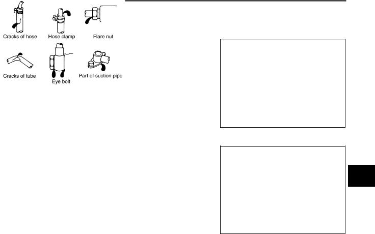
Checking Fluid Leakage
Check hydraulic connections for fluid leakage, cracks, damage, looseness, or wear.
1. Run engine until the fluid temperature reaches 50 to 80° C (122 to 176° F) in reservoir tank, and keep engine speed idle.
2.Turn steering wheel several times from full left stop to full right stop.
3.Hold steering wheel at each lock position for five seconds and carefully, check for fluid leakage.
CAUTION:
Do not hold the steering wheel in a locked position for more than 10 seconds. (There is the possibility that oil pump may be damaged.)
PFP:KLF20
AGS000KB
STC0996D
AGS000KC
SGIA0506E
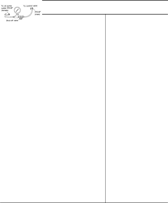
4.If fluid leakage at connections is noticed, then loosen flare nut and then retighten. Do not over tighten con-
nector as this can damage O-ring, washer and connector.
5.If fluid leakage from oil pump is noticed, check oil pump. Refer to PS-28, "POWER STEERING OIL PUMP" .
6.Check steering gear boots for accumulation of fluid indicating from steering gear.
Air Bleeding Hydraulic System |
AGS000KD |
If air bleeding is not complete, the following symptoms can be observed.
●Bubbles are created in reservoir tank.
●Clicking noise can be heard from oil pump.
●Excessive buzzing in the oil pump.
NOTE:
Fluid noise may occur in the valve or oil pump. This does not affect performance or durability of the system.
1.Turn steering wheel several times from full left stop to full right stop with engine off.
CAUTION:
Turn steering wheel while filling reservoir tank with fluid so as not to lower fluid level below the MIN line.
2.Start engine and hold steering wheel at each lock position for 3 seconds at idle to check for fluid leakage.
3.Repeat step 2 above several times at approximately 3 second intervals.
CAUTION:
Do not hold the steering wheel in a locked position for more than 10 seconds. (There is the possibility that oil pump may be damaged.)
4.Check fluid for bubbles and white contamination.
5.Stop engine if bubbles and white contamination do not drain out. Perform step 2 to 3 above after waiting until bubbles and white contamination drain out.
A
B
C
D
E
F
PS
H
I
J
K
L
M
Revision: 2006 July |
PS-7 |
2006 X-Trail |

POWER STEERING FLUID
6.Stop the engine, and then check fluid level.
Revision: 2006 July |
PS-8 |
2006 X-Trail |
STEERING WHEEL
STEERING WHEEL |
PFP:48430 |
On-Vehicle Inspection and Service |
AGS000KE |
CHECKING CONDITION OF INSTALLATION |
|
●Check installation conditions of steering gear assembly, front suspension, axle and steering column.
●Check if movement exists when steering wheel is moved up and down, to the left and right and to the axial direction.
Steering wheel axial end play : 0 mm (0 in)
●Check steering gear assembly mounting nuts and bolts for looseness. Refer to PS-17, "COMPONENT" .
CHECKING STEERING WHEEL PLAY
A
B
C
D
●Turn steering wheel so that front wheels come to the straight-ahead position. Start engine and lightly turn
steering wheel to the left and right until front wheels start to move. Measure steering wheel movement on the outer circumference.
Steering wheel play : 0 - 35 mm (0 - 1.38 in)
●When the measurement value is outside the standard value, check backlash for each joint of steering col-
umn and installation condition of power steering gear.
E
F
CHECKING NEUTRAL POSITION STEERING WHEEL
●Make sure that steering gear assembly, steering column and steering wheel are installed in the correct PS position.
●Perform neutral position inspection after wheel alignment. Refer to FSU-6, "Wheel Alignment Inspection" .
● Set vehicle to the straight-ahead position and confirm steering wheel is in the neutral position. |
H |
●Loosen outer socket lock nut and turn inner socket to left and right equally to make fine adjustments if steering wheel is not in the neutral position.
CHECKING STEERING WHEEL TURNING FORCE
1.Park vehicle on a level and dry surface, set parking brake.
2.Start engine.
3.Bring power steering fluid up to adequate operating temperature. [Make sure temperature of fluid is approximately 50 to 80° C (122 to 176° F).]
I
J
|
NOTE: |
|
K |
|
Tires need to be inflated normal pressure. |
|
|
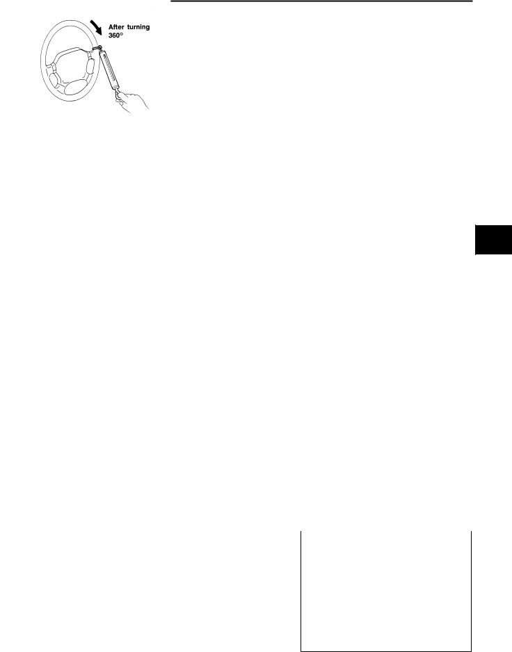
4. |
Check steering wheel turning force when steering wheel has |
|
|
|
|
||
|
been turned 360° from neutral position. |
|
L |
|
Steering wheel turning force |
|
|
|
|
|
|
|
: 36 N (3.7 kg, 8.2 lb) or less |
|
|
5. |
If steering wheel turning force is out of the specification, check |
|
M |
|
rack sliding force. |
|
|
a. |
Disconnect lower shaft and steering knuckle from steering gear |
|
|
|
assembly. |
|
|
b. |
Start and run engine at idle to make sure steering fluid has |
SST491B |
|
|
reached normal operating temperature. |
|
|
|
|
|
|
c. |
While pulling outer socket slowly in ± 11.5 mm (± 0.453 in) range |
|
|
|
|
||
|
from neutral position, make sure rack sliding force is within |
|
|
|
specification. |
|
|
|
Rack sliding force |
|
|
|
: 206 - 264 N (21 - 27 kg, 46.3 - 59.5 lb) |
|
|
d.If rack sliding force is not within specification, overhaul steering gear assembly.
SST090B
Revision: 2006 July |
PS-9 |
2006 X-Trail |

STEERING WHEEL
CHECKING FRONT WHEEL TURNING ANGLE
●Check front wheel turning angle after toe-in inspection. Place front wheels on turning radius gauges and rear wheels on stands. Check the maximum inner and outer wheel turning angles for LH and RH road wheels.
FAA0016D
●With the engine at idle, turn steering wheel from full left stop to full right stop and measure the turning angles.
|
Minimum |
36° 00′ (36.0° ) |
|
|
|
Inner wheel (Angle: A) |
Nominal |
39° 00′ (39.0° ) |
|
|
|
|
Maximum |
40° 00′ (40.0° ) |
|
|
|
Outer wheel (Angle: B) |
Nominal |
31° 00′ (31.0° ) |
|
|
|
SGIA0055E
●Measure rack stroke if angles are outside the specified value.
Rack stroke “L” : 66.5 mm (2.618 in)
●Disassemble steering gear to check the cause that rack stroke is outside of the standard.
●Steering angles are not adjustable. Check steering gear, steering column and front suspension components for wear or damage if any of the turning angles are different from the specified value. Replace any of them, if any non-standard condition exists.
|
SGIA0629J |
Removal and Installation |
AGS000KF |
REMOVAL |
|
1.Set front wheels in the straight-ahead direction.
2.Remove driver air bag module from steering wheel. Refer to SRS-31, "DRIVER AIR BAG MODULE" .
3.Remove steering wheel lock nut after steering is locked.
4.Remove steering wheel with the steering wheel puller [SST].
SGIA0939E
Revision: 2006 July |
PS-10 |
2006 X-Trail |
STEERING WHEEL
INSTALLATION
Install in the reverse order of the removal. For tightening torque, refer to PS-12, "COMPONENTS" .
NOTE:
●When reconnecting spiral cable, fix cable with a tape so that fixing case and rotating part keep aligned.
This will omit neutral position alignment procedure during spiral cable installation.
● Neutral position (refer to figure)... Gently turn spiral cable clock- |
|
|
wise until it comes to the stop. Then turn it counterclockwise |
|
|
(approximately 3.0 turns) until centering mark is aligned with |
|
|
adjustment mark. (Service part is fixed in neutral position with |
|
|
stopper. It can be installed onto steering wheel without align- |
|
|
ment once stopper is removed.) |
|
|
CAUTION: |
|
|
● Place steering wheel as follows: Front wheels in straight- |
|
|
ahead position. R mark on the cancel claw faces down. 3 |
|
|
bosses align with 3 holes behind steering wheel assembly. |
|
|
Make sure that spiral cable is placed in neutral position and |
SGIA0940E |
|
that locating pin on the left of the spiral cable is aligned |
||
|
||
with the locating pinhole behind the steering wheel assembly. |
|
A
B
C
D
E
F
PS
H
I
J
K
L
M
Revision: 2006 July |
PS-11 |
2006 X-Trail |
Loading...