


XTrail T30 2006
Table of contents
 Loading...
REAR FINAL DRIVE
D DRIVELINE/AXLE
A
B
SECTION RFD
CONTENTS
PRECAUTIONS .......................................................... 2
Service Notice or Precautions .................................. 2
PREPARATION .............................. .................... ......... 3
Special Service Tools ............................................... 3
Commercial Service Tools ........................................ 5
NOISE, VIBRATION AND HARSHNESS (NVH)
TROUBLESHOOTING .......................... ...................... 6
NVH Troubleshooting Chart ..................................... 6
DESCRIPTION ......................... ................................... 7
Cross-Sectional View ............................................... 7
DIFFERENTIAL GEAR OIL ........................................ 8
Changing Differential Gear Oil ................. ....... ......... 8
DRAINING ................................ ............. ................ 8
FILLING .............................. ...... ............................. 8
Checking Differential Gear Oil .................................. 8
OIL LEAKAGE AND OIL LEVEL ........................... 8
FRONT OIL SEAL ...................................................... 9
Removal and Installation .......................................... 9
REMOVAL ............................................................. 9
INSTALLATION ..................................................... 9
SIDE OIL SEAL .........................................................11
Removal and Installation .........................................11
REMOVAL ............................................................11
INSTALLATION ....................................................11
REAR FINAL DRIVE
ELECTRIC CONTROLLED COUPLING ................... 12
Removal and Installation ........................................ 12
REMOVAL ...........................................................12
INSTALLATION ................................................... 13
REAR FINAL DRIVE ASSEMBLY ............................ 14
Removal and Installation ........................................ 14
COMPONENTS ..................... .............................. 14
REMOVAL ...........................................................14
INSTALLATION ................................................... 15
Disassembly and Assembly ....................................16
COMPONENTS ..................... .............................. 16
ASSEMBL Y INSPECTI ON AND ADJUSTMENT ...17
DISASSEMBLY ................................................... 21
INSPECTION AFTER DISASSEMBLY ................24
ASSEMBLY ......................................................... 25
SERVICE DATA AND SPECIFICATIONS (SDS) ...... 34
General Specifications . ...... ....... ...... ........................ 34
Inspection and Adjustment ..................................... 34
DRIVE GEAR RUNOUT ......................................34
DIFFERENTIAL SIDE GEAR CLEARANCE .......34
PRELOAD TORQUE ........................................... 34
BACKLASH ......................................................... 34
COMPANION FLANGE RUNOUT .......................34
SELECTIVE PARTS ............................................ 34
C
RFD
E
F
G
H
I
J
K
L
M
Revision: 2006 July 2006 X-Trail
RFD-1

PRECAUTIONS
PRECAUTIONS PFP:00001 Service Notice or Precaution s ADS0015Z
● Check for the correct installation status prior to removal or disassembly. If matching marks are required,
be certain they do not interfere wi th the function of the parts when applied.
● Overhaul should be done in a clean work area , it is preferable to work in dustproof area.
● Before disassembly, using steam or white gasoline, completely remove sand and mud from the exterior of
the unit, preventing them from entering into the unit during disassembly or assembly.
● Check appearance of the disassembled parts for damage, deformation, and unusual wear. Replace them
with a new ones if necessary.
● Gaskets, seals and O-rings should be replaced any time when the unit is disassembled.
● In principle, tighten bolts or nuts gradually in several steps working diagonally from inside to outside. If
tightening sequence is specified, observe it.
● Clean and flush the parts suff iciently and blow-dry the m.
● Be careful no t to damage sliding surfa c es and mating surfaces.
● When applying sealant, remove the old sealant from the mounting surface; then remove any moisture, oil,
and foreign materials from the ap plication and mounti ng surfa ce s.
● Always use shop paper for cleaning the inside of components.
● Avoid using cotton gloves or shop rags to prevent entering of lint.
● During assembly, observe the specified tightening torque, and apply new differential oil, petroleum jelly, or
multi-purpose grease as specified for each vehicle, if necessary.
Revision: 2006 July 2006 X-Trail
RFD-2
PREPARATION
PREPARATION PFP:00002
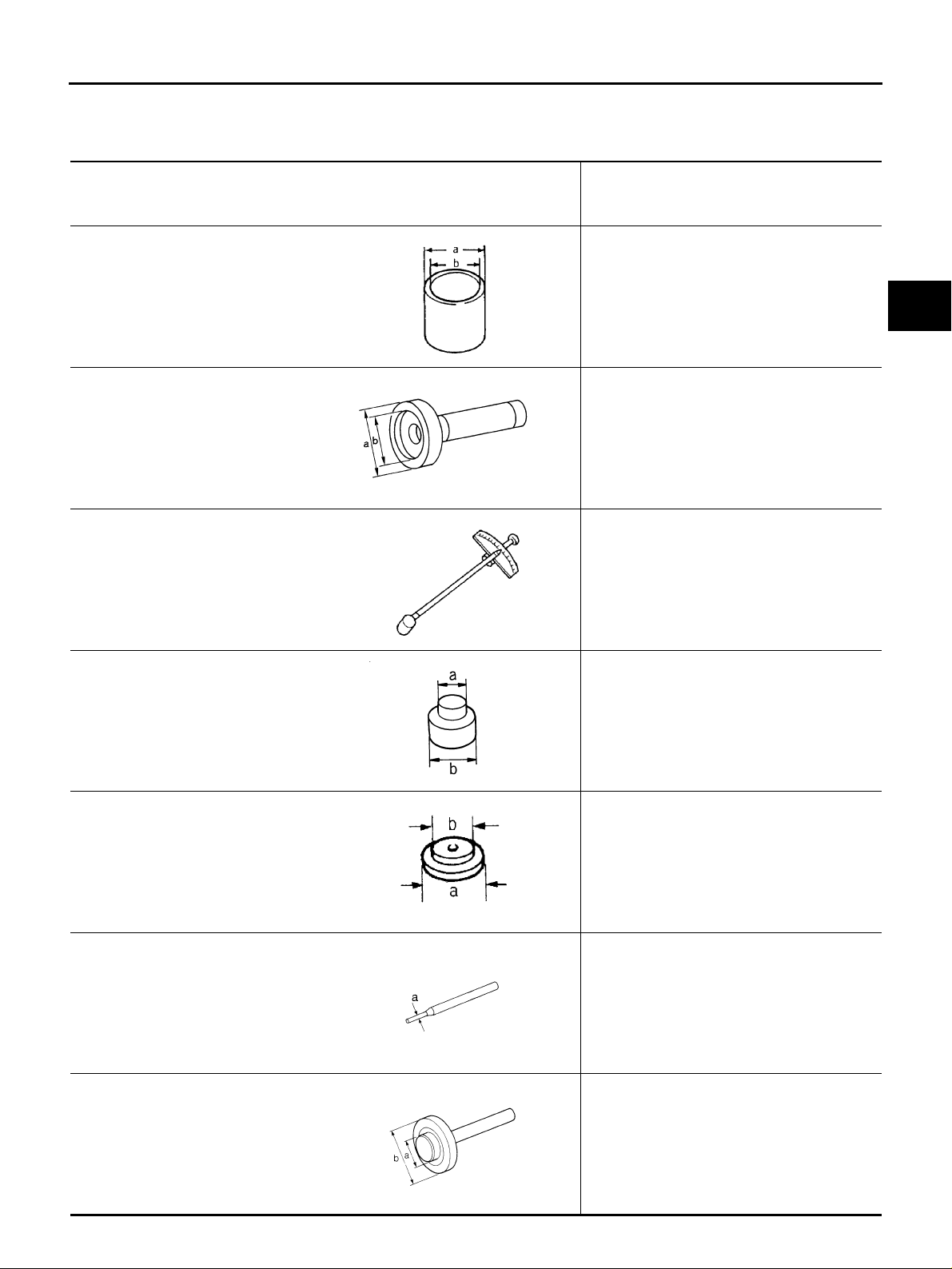
Special Service Tools ADS00160
The actual shapes of Kent-Moore tools may differ from those of spec ial ser vi ce tool s illust rat ed here.
Tool number
(Kent-Moore No.)
Tool name
Description
A
B
ST27861000
(—)
Drift
a: 62 mm (2.44 in) dia.
b: 52 mm (2.05 in) dia.
KV38100200
(J-26233)
Drift
a: 65 mm (2.56 in) dia.
b: 49 mm (1.93 in) dia.
ST3127S000
(J-25765-A)
Preload gauge
ST33052000
(—)
Drift
a: 22 mm (0.87 in) dia.
b: 28 mm (1.10 in) dia.
KV40100610
(J-26089)
Drift
a: 63 mm (2.48 in) dia.
b: 54.3 mm (2.138 in) dia.
ZZA0832D
ZZA1143D
ZZA0503D
ZZA1023D
Installing final drive front oil seal
● Installing final drive front oil seal
● Installing final drive side oil seal
Measuring preload torque
Removing side bearing inner race
● Removing and installing gear carrier and
rear cover (2 pieces are used)
● Installing pinion front bearing inner race
C
RFD
E
F
G
H
I
J
K
L
M
ZZA0810D
ST23550000
(—)
Pin punch
a: 4.5 mm (0.177 in) dia.
NT410
ST17130000
(—)
Drift
a: 31.8 mm (1.252 in) dia.
b: 58 mm (2.28 in) dia.
ZZA0836D
Revision: 2006 July 2006 X-Trail
RFD-3
Removing and installing lock pin
Installing pinion rear bearing outer race
Tool number
(Kent-Moore No.)
Tool name
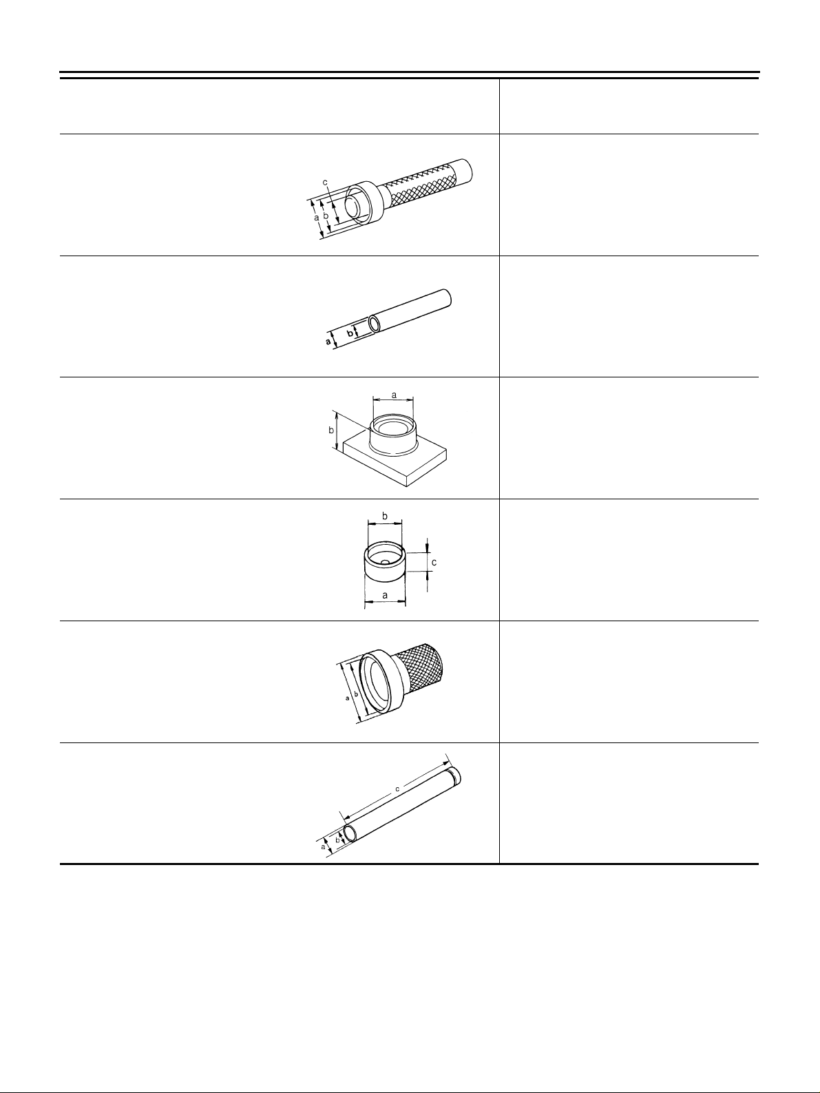
PREPARATION
Description
ST33230000
(J-25805-01)
Drift
a: 51 mm (2.01 in) dia.
b: 41 mm (1.61 in) dia.
c: 28.5 mm (1.122 in) dia.
ST23860000
(—)
Drift
a: 38 mm (1.50 in) dia.
b: 33 mm (1.30 in) dia.
ST38220000
(—)
Press stand
a: 63 mm (2.48 in) dia.
b: 65 mm (2.56 in)
KV40105020
(—)
Drift
a: 39.7 mm (1.563 in) dia.
b: 35 mm (1.38 in) dia.
c: 15 mm (0.59 in)
Installing pinion front bearing outer race
ZZA1046D
● Installing pinion rear bearing inner race
● Installing pinion front bearing inner race
ZZA0534D
Installing pinion front bearing inner race
ZZA1058D
Installing side bearing inner race
ST35271000
(J-26091)
Drift
a: 72 mm (2.83 in) dia.
b: 63 mm (2.48 in) dia.
ST22360002
(J-25679-01)
Drift
a: 29 mm (1.14 in) dia.
b: 23 mm (0.91 in) dia.
c: 150 mm (5.91 in)
ZZA1133D
Installing center oil seal
ZZA0814D
Installing coupling front bearing
ZZA0546D
Revision: 2006 July 2006 X-Trail
RFD-4
PREPARATION
Tool number
(Kent-Moore No.)
Tool name
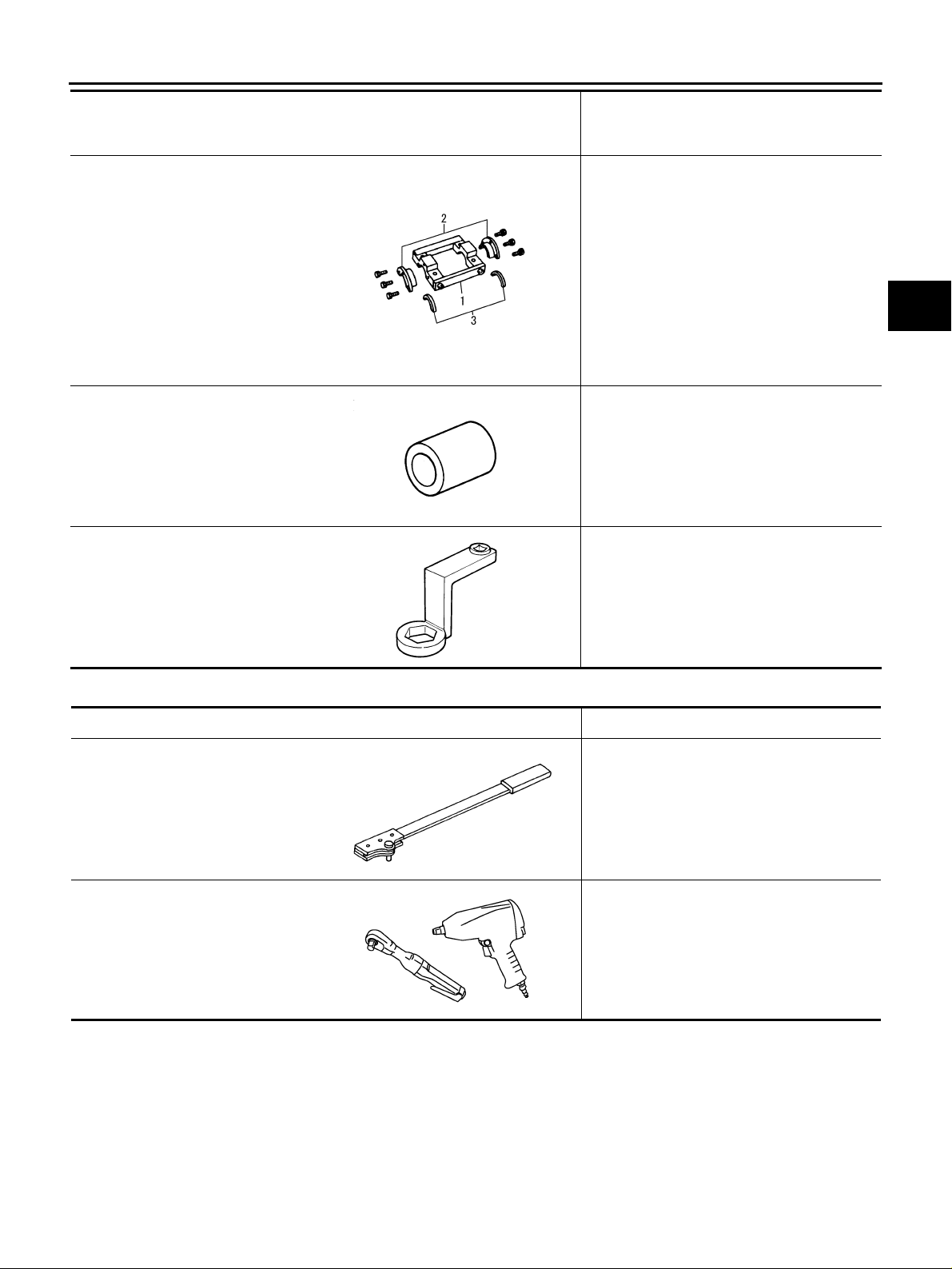
KV381086S1
(—)
Dummy cover set
1.KV38108610
(—)
Dummy cover
2.KV38108621
(—)
Dummy cover space r
3.KV38108630
(—)
Dummy cover shim
KV38108500
(—)
Drive pinion socket
KV38108400
(—)
Pinion nut wrench
SDIA2313E
ZZA1205D
Description
● Checking backlash
● Checking drive gear runout
● Checking tooth contact
● Measuring preload torque
● Removing and installing drive pinion nut
● Measuring preload torque
● Removing drive pinion nut
A
B
C
RFD
E
F
G
H
ZZA1206D
Commercial Service Tools ADS0018A
Tool name Description
Flange wrench Removing and installing companion flange
lock nut
NT771
Power tool Loosening nuts and bolts
PBIC0190E
I
J
K
L
M
Revision: 2006 July 2006 X-Trail
RFD-5

NOISE, VIBRATION AND HARSHNESS (NVH) TROUBLESHOOTING
NOISE, VIBRATION AND HARSHNESS (NVH) TROUBLESHOOTING PFP:00003 NVH Troubleshooting Chart ADS00161
Use the chart below to help you find the caus e of the symptom. If necessary, repair or replace these parts.
Reference page
Companion Flange Runout" .
Refer to RFD-18, "Tooth Contact" .
Gear contact improper
Refer to RFD-24, "INSPECTION AFTER DISASSEMBLY" .
Tooth surfaces wor n
Refer to RFD-24, "INSPECTION AFTER DISASSEMBLY" .
Possible cause and SUSPECTED PARTS
Gear tooth rough
Symptom Noise ЧЧЧЧЧЧЧЧЧЧЧЧЧ
×: Applicable
Refer to RFD-20, "Backlash" .
Backlash incorrect
Refer to RFD-20, "
Refer to RFD-8, "Checking Differential Gear Oil" .
NVH in PR section.
NVH in FAX, RAX, FSU and RSU sections.
NVH in WT section.
NVH in WT section.
NVH in FAX and RAX section.
NVH in BR section.
Companion flange excessive runout
Gear oil improper
PROPELLER SHAFT
AXLE AND SUSPENSION
TIRES
ROAD WHEEL
DRIVE SHAFT
BRAKES
NVH in PS section.
STEERING
Revision: 2006 July 2006 X-Trail
RFD-6
DESCRIPTION
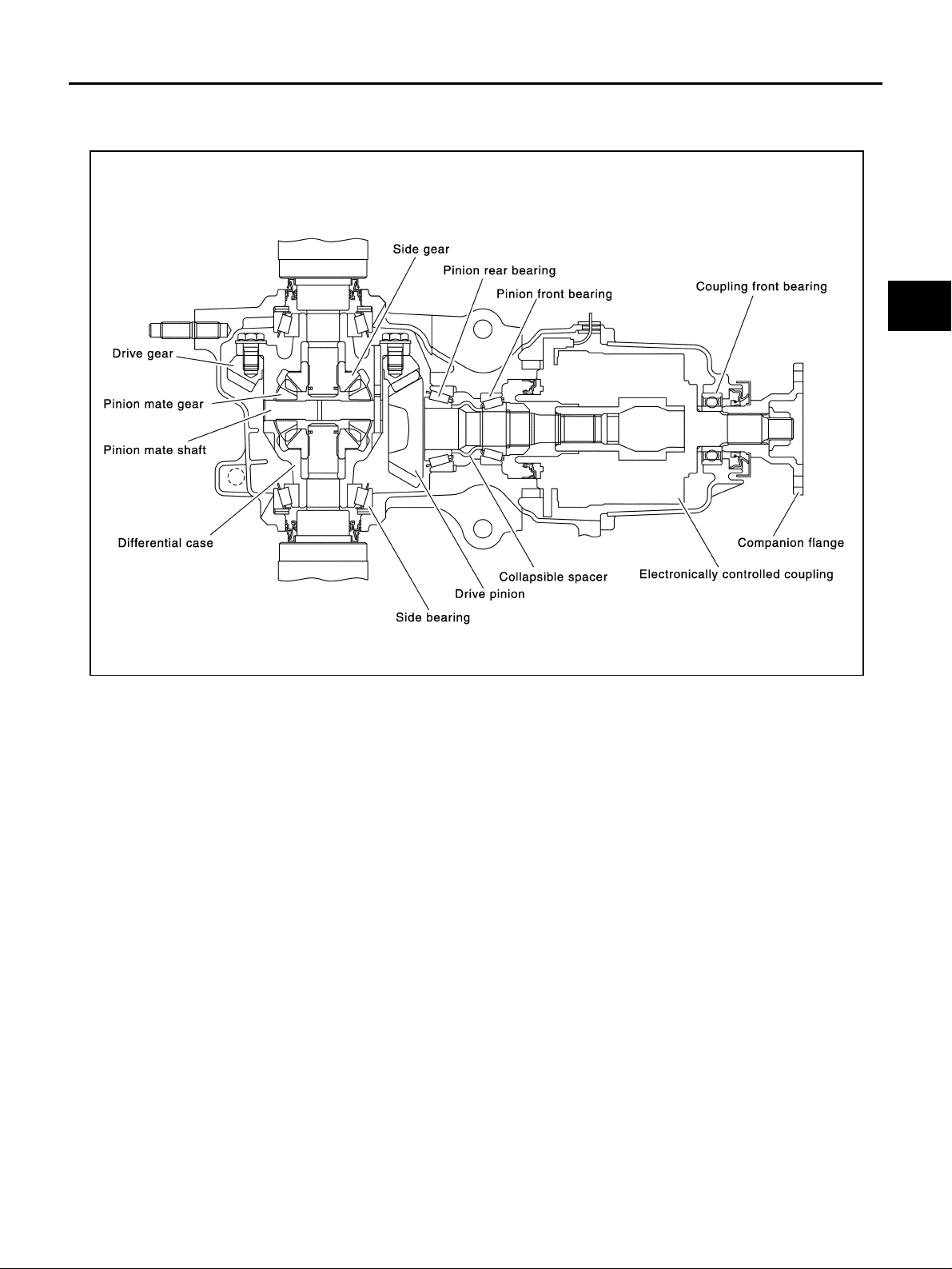
DESCRIPTION PFP:00000
Cross-Sectional View ADS0018B
A
B
C
RFD
E
F
G
SDIA0141E
H
I
J
K
L
M
Revision: 2006 July 2006 X-Trail
RFD-7

DIFFERENTIAL GEAR OIL
DIFFERENTIAL GEAR OIL PFP:KLD30 Changing Differential Gear Oil ADS0018C
DRAINING
1. Stop engine.
2. Remove drain plug and drain oil.
3. Set a gasket on drain plug and install it to final drive assembly
and tighten to the specifie d torque. Refer to RFD-16, "
NENTS" .
CAUTION:
Do not reuse gasket.
FILLING
1. Remove filler plug. Fill with new oil until oil level reaches the
specified level near filler plug mounting hole.
Oil grade and Viscosity:
Refer to MA-10, "
Oil capacity:
Approx. 0.55 (1-1/8 US pt, 1 Imp pt)
Fluids and Lubricants" .
COMPO-
PDIA0454E
2. After refilling oil, check oil level. Set a gasket to filler plug, t hen
install it to final drive assembly. Refer to RFD-16, "
NENTS" .
COMPO-
PDIA0453E
CAUTION:
Do not reuse gasket.
Checking Differential Gear Oil ADS0018D
OIL LEAKAGE AND OIL LEVEL
● Make sure tha t oil is not leaking from final drive assembly or around it.
● Check oil level from filler plug mounting hole as shown in the fig-
ure.
CAUTION:
Do not start engine while checking oil level.
● Set a gasket on filler plug and install it on final drive assembly.
Refer to RFD-16, "
CAUTION:
Do not reuse gasket.
COMPONENTS" .
PDIA0453E
Revision: 2006 July 2006 X-Trail
RFD-8
FRONT OIL SEAL
FRONT OIL SEAL PFP:38189
Removal and Installation ADS0016K
REMOVAL
1. Remove propeller shaft. Refer to PR-4, "Removal and Installation" .
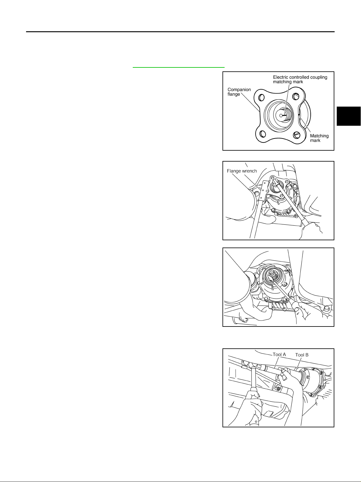
2. Put matching mark on the thread edge of electric controlled coupling. The matching mark should be in line with the matching
mark on companion flange.
CAUTION:
For matching mark, use paint. Do not damage electri c controlled coupling.
PDIA0455E
A
B
C
RFD
E
3. Remove companion flange lock nut, using a flange wrench.
Then remove compan io n flange.
4. Remove front oil seal from coupling c over, using a flat-bladed
screwdriver.
CAUTION:
Be careful not to damage coupling cover.
INSTALLATION
1. Apply multi-purpose grease to front oil seal lips.
2. Install front oil seal until it becomes flush with the case end,
using the drifts.
Tool numbe r A: KV38100200 (J-2623 3)
B: ST27861000 ( — )
PDIA0456E
PDIA0457E
F
G
H
I
J
K
L
M
CAUTION:
● Do not reuse oil seal.
● When installing, do not incline oil seal.
PDIA0038E
Revision: 2006 July 2006 X-Trail
RFD-9

FRONT OIL SEAL
3. Align the matching mark of electric controlled coupling with the
matching mark o f companion f lange, then install the co mpanion
flange.
4. Install companion flange lock nut with a flange wrench, tighten
the to the specified torque. Refer to RFD-16, "
CAUTION:
Do not reus e companion flange lock nut.
5. Install propeller s haft. Refer to PR-4, "
.
Removal and Installation"
COMPONENTS" .
PDIA0455E
Revision: 2006 July 2006 X-Trail
RFD-10
SIDE OIL SEAL
SIDE OIL SEAL PFP:38343
Removal and Installation ADS0016L
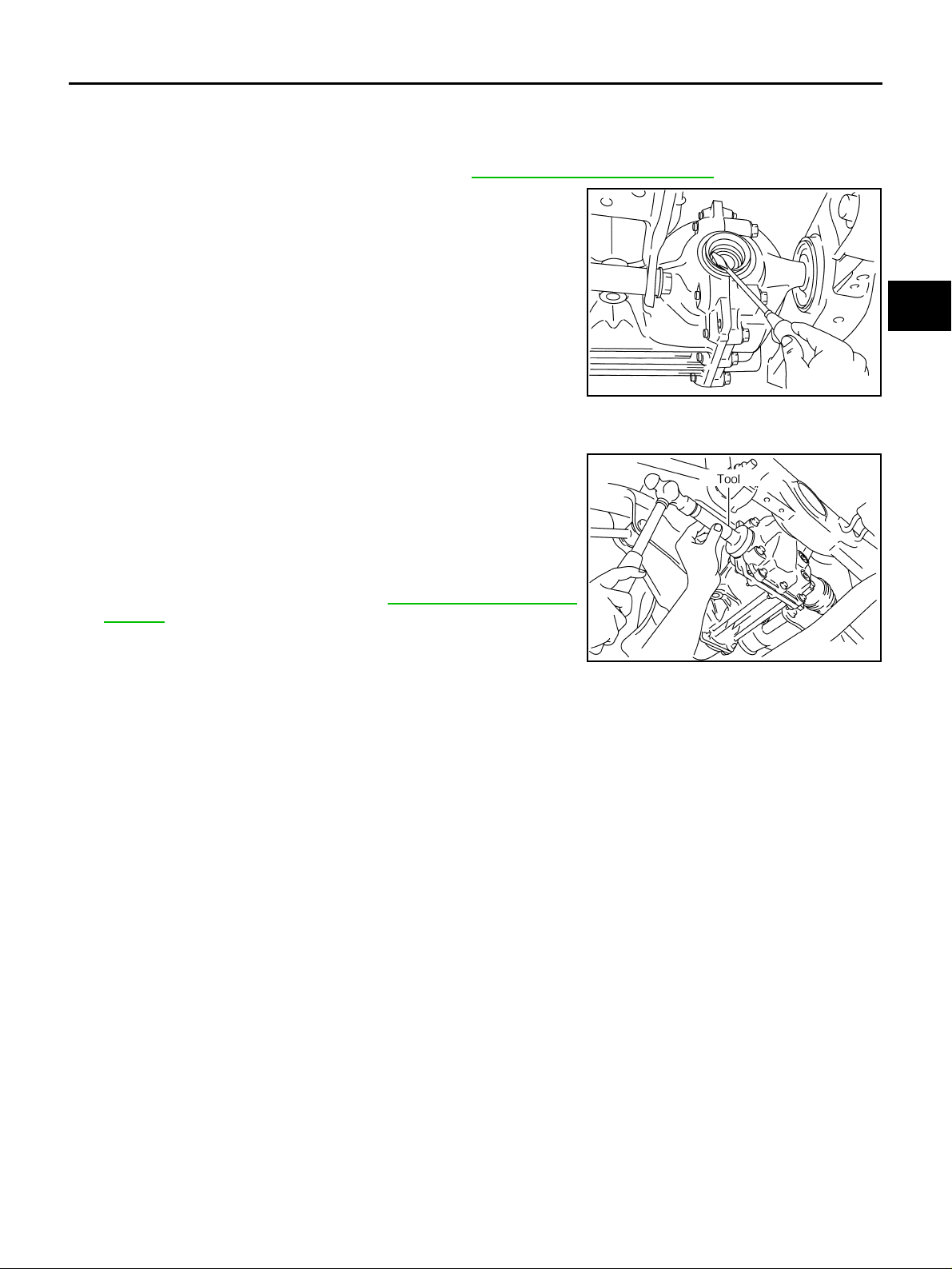
REMOVAL
1. Remove rear drive shaft with power tool. Refer to RAX-21, "REAR DRIVE SHAFT" .
2. Remove side oil seal, using a flat-bladed screwdriver.
CAUTION:
Be careful not to damage gear carrier and rear cover.
PDIA0431E
INSTALLATION
1. Apply multi-purpose grease to side oil seal lips.
2. Install side oil seal until it becomes flush with the case end,
using the drift.
Tool numbe r : KV38100200 (J-2623 3)
A
B
C
RFD
E
F
G
CAUTION:
● Do not reuse oil seal.
● When installing, do not incline oil seal.
3. Install rear drive shaft. Refer to RAX-21, "
SHAFT" .
H
REAR DRIVE
I
PDIA0432E
J
K
L
M
Revision: 2006 July 2006 X-Trail
RFD-11
Loading...