


 Loading...
D DRIVELINE/AXLE
SECTION TF
TRANSFER
CONTENTS
A
B
C
TF
E
PRECAUTIONS ......................................................... |
3 |
Precautions for Supplemental Restraint System |
|
(SRS) “AIR BAG” and “SEAT BELT PRE-TEN- |
|
SIONER” ................................................................. |
3 |
Precautions ............................................................. |
3 |
Service Notice or Precautions ................................. |
4 |
PREPARATION .......................................................... |
5 |
Special Service Tools .............................................. |
5 |
Commercial Service Tools ....................................... |
7 |
NOISE, VIBRATION AND HARSHNESS (NVH) |
|
TROUBLESHOOTING ............................................... |
8 |
NVH Troubleshooting Chart .................................... |
8 |
TRANSFER OIL ......................................................... |
9 |
Changing Transfer Oil ............................................. |
9 |
DRAINING ............................................................ |
9 |
FILLING ................................................................ |
9 |
Checking Transfer Oil .............................................. |
9 |
OIL LEAKAGE AND OIL LEVEL .......................... |
9 |
AWD SYSTEM ......................................................... |
10 |
Power Transfer Diagram ....................................... |
10 |
System Description ............................................... |
10 |
ELECTRIC CONTROLLED COUPLING ............ |
10 |
AWD CONTROL UNIT ....................................... |
10 |
AWD MODE SWITCH ......................................... |
11 |
AWD INDICATOR LAMP AND LOCK INDICA- |
|
TOR LAMP .......................................................... |
11 |
AWD WARNING LAMP ....................................... |
11 |
System Diagram .................................................... |
12 |
COMPONENTS FUNCTION DESCRIPTION .... |
13 |
CAN Communication ............................................. |
13 |
SYSTEM DESCRIPTION ................................... |
13 |
TROUBLE DIAGNOSIS ........................................... |
14 |
Fail-Safe Function ................................................. |
14 |
How to Perform Trouble Diagnosis ....................... |
14 |
BASIC CONCEPT .............................................. |
14 |
Location of Electrical Parts .................................... |
15 |
Circuit Diagram ..................................................... |
16 |
Wiring Diagram — AWD — ................................. |
... 17 |
Trouble Diagnosis Chart for Symptoms ................ |
20 |
AWD Control Unit Input/Output Signal Reference |
|
Values .................................................................... |
21 |
AWD CONTROL UNIT INSPECTION TABLE .... |
21 |
CONSULT-II Function (ALL MODE AWD/4WD) .... |
22 |
FUNCTION ......................................................... |
22 |
CONSULT-II SETTING PROCEDURE ............... |
22 |
SELF-DIAG RESULTS MODE ........................... |
23 |
DATA MONITOR MODE ..................................... |
24 |
ACTIVE TEST MODE ........................................ |
25 |
AWD CONTROL UNIT PART NUMBER ............ |
25 |
TROUBLE DIAGNOSIS FOR SYSTEM ................... |
26 |
Power Supply Circuit for AWD Control Unit ........... |
26 |
CONSULT-II REFERENCE VALUE IN DATA |
|
MONITOR MODE ............................................... |
26 |
DIAGNOSTIC PROCEDURE ............................. |
26 |
AWD Control Unit .................................................. |
27 |
DIAGNOSTIC PROCEDURE ............................. |
27 |
ABS System .......................................................... |
28 |
DIAGNOSTIC PROCEDURE ............................. |
28 |
AWD Solenoid ....................................................... |
28 |
CONSULT-II REFERENCE VALUE IN DATA |
|
MONITOR MODE ............................................... |
28 |
DIAGNOSTIC PROCEDURE ............................. |
29 |
COMPONENT INSPECTION ............................. |
31 |
AWD Actuator Relay .............................................. |
32 |
CONSULT-II REFERENCE VALUE IN DATA |
|
MONITOR MODE ............................................... |
32 |
DIAGNOSTIC PROCEDURE ............................. |
32 |
AWD Mode Switch ................................................. |
33 |
CONSULT-II REFERENCE VALUE IN DATA |
|
MONITOR MODE ............................................... |
33 |
DIAGNOSTIC PROCEDURE ............................. |
33 |
COMPONENT INSPECTION ............................. |
35 |
Engine Control Signal ............................................ |
35 |
DIAGNOSTIC PROCEDURE ............................. |
35 |
CAN Communication Line ..................................... |
36 |
DIAGNOSTIC PROCEDURE ............................. |
36 |
TROUBLE DIAGNOSIS FOR SYMPTOMS ............. |
37 |
AWD Indicator Lamp and LOCK Indicator Lamp Do |
|
Not Turn ON for Approx. 1 Second When Ignition |
|
Switch Is Turned to ON ......................................... |
37 |
F
G
H
I
J
K
L
M
Revision: 2006 July |
TF-1 |
2006 X-Trail |

DIAGNOSTIC PROCEDURE ............................. |
37 |
AWD Warning Lamp Does Not Turn ON When Igni- |
|
tion Switch Is Turned to ON ................................... |
38 |
DIAGNOSTIC PROCEDURE ............................. |
38 |
AWD Warning Lamp Does Not Turn OFF Several |
|
Seconds After Engine Started ................................ |
39 |
DIAGNOSTIC PROCEDURE ............................. |
39 |
AWD Mode Cannot Be Switched After Engine Is |
|
Started ................................................................... |
40 |
DIAGNOSTIC PROCEDURE ............................. |
40 |
Heavy Tight-Corner Braking Symptom Occurs |
|
WhenVehicle Is DriveninAUTO Mode and Steering |
|
Wheel Is Turned Fully to Either Side after Engine |
|
Is Started ............................................................... |
41 |
DIAGNOSTIC PROCEDURE ............................. |
41 |
Vehicle Does Not Enter AWD Mode Even Though |
|
AWD Warning Lamp Turned to OFF ...................... |
42 |
DIAGNOSTIC PROCEDURE ............................. |
42 |
WhileDriving,AWDWarningLampFlashesRapidly |
|
(When Flashing in Approx. 1 Minute and Then Turn- |
|
ing OFF) ................................................................ |
43 |
While Driving, AWD Warning Lamp Flashes Slowly |
|
(When Continuing to Flash Until Turning Ignition |
|
Switch OFF) ........................................................... |
43 |
DIAGNOSTIC PROCEDURE ............................. |
43 |
AWD CONTROL UNIT ............................................. |
45 |
Removal and Installation ....................................... |
45 |
REMOVAL .......................................................... |
45 |
INSTALLATION ................................................... |
45 |
SIDE OIL SEAL ........................................................ |
46 |
Removal and Installation ........................................ |
46 |
REMOVAL ........................................................... |
46 |
INSTALLATION ................................................... |
46 |
AIR BREATHER HOSE ............................................ |
47 |
Components ........................................................... |
47 |
Removal and Installation ........................................ |
47 |
TRANSFER ASSEMBLY .......................................... |
48 |
Removal and Installation ........................................ |
48 |
COMPONENTS .................................................. |
48 |
REMOVAL ........................................................... |
48 |
INSTALLATION ................................................... |
49 |
Disassembly and Assembly ................................... |
50 |
COMPONENTS .................................................. |
50 |
ASSEMBLY INSPECTION .................................. |
51 |
DISASSEMBLY ................................................... |
55 |
INSPECTION AFTER DISASSEMBLY ............... |
59 |
SELECTING ADJUSTING SHIMS ...................... |
60 |
ASSEMBLY ......................................................... |
62 |
SERVICE DATA AND SPECIFICATIONS (SDS) .....67 |
|
General Specifications ........................................... |
67 |
Inspection and Adjustment ..................................... |
67 |
PRELOAD TORQUE BEFORE DISASSEMBLY... |
67 |
PRELOAD TORQUE AFTER DISASSEMBLY |
|
AND REASSEMBLY ........................................... |
67 |
BACKLASH ......................................................... |
67 |
COMPANION FLANGE RUNOUT ...................... |
67 |
SELECTIVE PARTS ........................................... |
67 |
Revision: 2006 July |
TF-2 |
2006 X-Trail |

|
PRECAUTIONS |
|
|
|
|
|
|
PRECAUTIONS |
PFP:00001 |
A |
|
Precautions for Supplemental Restraint System (SRS) “AIR BAG” and “SEAT |
|||
|
|||
BELT PRE-TENSIONER” |
ADS0016Z |
|
|
The Supplemental Restraint System such as “AIR BAG” and “SEAT BELT PRE-TENSIONER”, used along B |
||
with a front seat belt, helps to reduce the risk or severity of injury to the driver and front passenger for certain |
|
|
types of collision. Information necessary to service the system safely is included in the SRS and SB section of |
|
|
this Service Manual. |
C |
|
WARNING: |
||
|
||
● To avoid rendering the SRS inoperative, which could increase the risk of personal injury or death |
|
|
|
||
in the event of a collision which would result in air bag inflation, all maintenance must be per- |
TF |
|
formed by an authorized NISSAN/INFINITI dealer. |
|
|
●Improper maintenance, including incorrect removal and installation of the SRS, can lead to personal injury caused by unintentional activation of the system. For removal of Spiral Cable and Air
Bag Module, see the SRS section. |
E |
●Do not use electrical test equipment on any circuit related to the SRS unless instructed to in this Service Manual. SRS wiring harnesses can be identified by yellow and/or orange harnesses or
harness connectors.
Precautions
●Before connecting or disconnecting the AWD control unit harness connector, turn ignition switch “OFF” and disconnect battery negative cable from battery negative terminal. Because battery voltage is applied to AWD control unit even if ignition switch is turned “OFF”.
●When connecting or disconnecting pin connectors into or from AWD control unit, take care not to damage pin terminals (bend or break).
When connecting pin connectors, make sure that there are no bends or breaks on AWD control unit pin terminal.
ADS00170
SEF289H
F
G
H
I
J
K
L
M
SEF291H
●Before replacing AWD control unit, perform AWD control unit input/output signal inspection and make sure whether AWD control unit functions properly or not. Refer to TF-21, "AWD Control Unit Input/Output Signal Reference Values" .
SDIA1848E
Revision: 2006 July |
TF-3 |
2006 X-Trail |

PRECAUTIONS
Service Notice or Precautions |
ADS00171 |
●After overhaul refill the transfer with new transfer oil.
●Check the oil level or replace oil only with the vehicle parked on level surface.
●During removal or installation, keep inside of transfer clear of dust or dirt.
●Replace all tires at the same time. Always use tires of the proper size and the same brand and pattern. Fitting improper size and/or unusual wear tires applies excessive force to vehicle mechanism and can cause longitudinal vibration.
●Disassembly should be done in a clean work area.
●Before proceeding with disassembly, thoroughly clean the transfer. It is important to prevent the internal parts from becoming contaminated by dirt or other foreign matter.
●Check for the correct installation status prior to removal or disassembly. If matching marks are required, be certain they do not interfere with the function of the parts when applied.
●All parts should be carefully cleaned with a general purpose, non-flammable solvent before inspection or reassembly.
●Check appearance of the disassembled parts for damage, deformation, and unusual wear. Replace them with a new ones if necessary.
●Gaskets, seals, O-rings and lock nuts should be replaced any time when the transfer is disassembled.
●In principle, tighten bolts or nuts gradually in several steps working diagonally from inside to outside. If tightening sequence is specified, use it.
●Observe the specified torque when assembling.
●Clean and flush the parts sufficiently and blow-dry them.
●Be careful not to damage sliding surfaces and mating surfaces.
●Use lint-free cloth or towels for wiping parts clean. Common shop rags can leave fibers that could interfere with the operation of the transfer.
Revision: 2006 July |
TF-4 |
2006 X-Trail |
|
PREPARATION |
|
|
PREPARATION |
PFP:00002 |
Special Service Tools |
ADS00173 |
The actual shapes of Kent-Moore tools may differ from those of special service tools illustrated here.
Tool number
(Kent-Moore No.) Description Tool name
KV38101700 |
Installing side oil seal (installing adapter case |
||
( |
— |
) |
oil seal) |
Drift |
|
|
|
a:82 mm (3.23 in) dia.
b:78 mm (3.07 in) dia.
|
ZZA1149D |
|
|
ST3127S000 |
Measuring preload torque |
(J-25765-A) |
|
Preload gauge |
|
|
ZZA0503D |
|
|
ST33220000 |
Removing drive pinion |
(J-25804-01) |
|
Drift |
|
a:37 mm (1.46 in) dia.
b:31 mm (1.22 in) dia.
c:22 mm (0.87 in) dia.
|
ZZA1046D |
|
|
|
|
KV381054S0 |
● Removing pinion rear bearing outer race |
|
(J-34286) |
● Removing pinion front bearing outer race |
|
Puller |
||
● Removing gear ring oil seal |
||
|
|
ZZA0601D |
|
|
ST30031000 |
Removing pinion front bearing inner race |
(J-22912-01) |
|
Replacer |
|
|
ZZA0700D |
|
|
ST33200000 |
● Removing gear ring bearing inner race |
(J-26082) |
(adapter case side) |
Drift |
● Installing companion flange |
|
a:60 mm (2.36 in) dia.
b:44.5 mm (1.752 in) dia.
|
ZZA1002D |
|
|
ST33061000 |
Removing gear ring bearing inner race |
(J-8107-2) |
(transfer case side) |
Drift |
|
a:38 mm (1.50 in) dia.
b:28.5 mm (1.122 in) dia.
ZZA0810D
A
B
C
TF
E
F
G
H
I
J
K
L
M
Revision: 2006 July |
TF-5 |
2006 X-Trail |

PREPARATION
Tool number
(Kent-Moore No.) Description Tool name
ST30720000 |
● Installing gear ring bearing outer race |
|||
(J-25405) |
|
(transfer case side) |
||
Drift |
|
|
● Installing gear ring bearing inner race |
|
a: 77 mm (3.03 in) dia. |
||||
(transfer case side) |
||||
b: 55.5 mm (2.185 in) dia. |
||||
● Installing gear ring bearing inner race |
||||
|
|
|
||
|
|
|
(adapter case side) |
|
|
|
|
● Installing gear ring bearing outer race |
|
|
|
ZZA0811D |
(adapter case side) |
|
|
|
|
● Installing transfer case oil seal |
|
|
|
|||
KV40101840 |
Installing gear ring bearing outer race |
|||
( |
— |
) |
(transfer case side) |
|
Drift |
|
|
|
|
a:77 mm (3.03 in) dia.
b:85 mm (3.35 in) dia.
|
ZZA0881D |
|
|
ST33230000 |
Installing gear ring oil seal |
(J-25805-01) |
|
Drift |
|
a:51 mm (2.01 in) dia.
b:41 mm (1.61 in) dia.
c:28.5 mm (1.122 in) dia.
|
|
|
ZZA1046D |
|
|
||
ST27863000 |
Installing gear ring bearing inner race |
||
( |
— |
) |
(transfer case side) |
Drift |
|
|
|
a:74.5 mm (2.933 in) dia.
b:62.5 mm (2.461 in) dia.
|
ZZA1003D |
|
|
KV40101630 |
Installing gear ring bearing inner race |
(J-35870) |
(transfer case side) |
Drift |
|
a:68 mm (2.68 in) dia.
b:60 mm (2.36 in) dia.
|
|
|
ZZA1003D |
|
|
||
KV38102510 |
Installing gear ring bearing inner race |
||
( |
— |
) |
(adapter case side) |
Drift |
|
|
|
a:71 mm (2.80 in) dia.
b:65 mm (2.56 in) dia.
|
|
|
ZZA1003D |
|
|
||
KV40105230 |
Installing gear ring bearing outer race |
||
( |
— |
) |
(adapter case side) |
Drift |
|
|
|
a:92 mm (3.62 in) dia.
b:86 mm (3.39 in) dia.
ZZA1141D
Revision: 2006 July |
TF-6 |
2006 X-Trail |
PREPARATION
Tool number |
|
(Kent-Moore No.) |
Description |
Tool name |
|
|
|
KV38100300 |
Installing pinion rear bearing outer race |
(J-25523) |
|
Drift |
|
a:54 mm (2.13 in) dia.
b:46 mm (1.81 in) dia.
c:32 mm (1.26 in) dia.
|
ZZA1046D |
|
|
|
|
ST33400001 |
● Installing pinion front bearing outer race |
|
(J-26082) |
● Installing pinion sleeve oil seal |
|
Drift |
||
|
a:60 mm (2.36 in) dia.
b:47 mm (1.85 in) dia.
|
ZZA0814D |
|
|
|
|
ST30901000 |
● Installing pinion front bearing outer race |
|
(J-26010-01) |
● Installing pinion front bearing inner race |
|
Drift |
||
|
a:79 mm (3.11 in) dia.
b:45 mm (1.77 in) dia.
c:35.2 mm (1.386 in) dia.
|
ZZA0978D |
|
|
Commercial Service Tools |
ADS00189 |
|
|
Tool name |
Description |
|
|
Power tool |
Loosening nuts and bolts |
PBIC0190E
A
B
C
TF
E
F
G
H
I
J
K
L
M
Revision: 2006 July |
TF-7 |
2006 X-Trail |

NOISE, VIBRATION AND HARSHNESS (NVH) TROUBLESHOOTING
NOISE, VIBRATION AND HARSHNESS (NVH) TROUBLESHOOTING
NVH Troubleshooting Chart
PFP:00003
ADS00174
Use the chart below to help you find the cause of the symptom. The numbers indicate the order of the inspection. If necessary, repair or replace these parts.
Reference page |
|
TF-9 |
|
|
TF-50 |
|
TF-50 |
|
TF-50 |
|
TF-59 |
|
TF-59 |
|
|
|
|
|
|
|
|
|
|
||||||||
|
|
|
|
|
|
|
|
||||||||
|
|
|
|
|
|
|
|
|
|
||||||
|
|
|
|
|
|
|
|
|
|
|
|
|
|
|
|
SUSPECTED PARTS |
TRANSFER OIL (Level low) |
TRANSFER OIL (Wrong) |
TRANSFER OIL (Level too high) |
LIQUID GASKET (Damaged) |
O-RING (Worn or damaged) |
OIL SEAL (Worn or damaged) |
GEAR (Worn or damaged) |
BEARING (Worn or damaged) |
|||||||
(Possible cause) |
|||||||||||||||
|
|
||||||||||||||
|
|
|
|
|
|
|
|
|
|
|
|
|
|||
Symptom |
Noise |
1 |
2 |
|
|
|
|
|
|
|
3 |
3 |
|||
|
|
|
|
|
|
|
|
|
|
|
|
|
|
|
|
Transfer oil leakage |
|
3 |
1 |
2 |
2 |
2 |
|
|
|
|
|||||
|
|
|
|
|
|
||||||||||
|
|
|
|
|
|
|
|
|
|
|
|
|
|
|
|
Revision: 2006 July |
TF-8 |
2006 X-Trail |

|
TRANSFER OIL |
|
|
TRANSFER OIL |
PFP:KLD30 |
Changing Transfer Oil |
ADS00175 |
DRAINING |
|
CAUTION:
When draining oil, protect exhaust tube with cover.
1.Run vehicle to warm up transfer body sufficiently.
2.Stop engine, and remove drain plug to drain transfer oil.
3.Apply sealant to drain plug. Install drain plug on transfer and tighten to the specified torque. Refer to TF-50, "COMPONENTS" .
●Use Genuine Silicone RTV or equivalent. Refer to GI-47, "Recommended Chemical Products and Sealants" .
SDIA0512E
FILLING |
|
1. Remove filler plug and add gear oil until oil level reaches the |
|
specified limit near filler plug mounting hole. |
|
Oil grade and Viscosity: |
|
Refer to MA-10, "Fluids and Lubricants" . |
|
Oil capacity: |
|
Approx. 0.31 (5/8 US pt, 1/2 lmp pt) |
|
CAUTION: |
|
Carefully fill oil. (Fill up for approx. 3 minutes) |
|
2. Leave vehicle for 3 minutes, and check oil level again. |
SDIA0513E |
3.Apply sealant to filler plug. Install filler plug on transfer and tighten to the specified torque. Refer to TF-50, "COMPONENTS" .
●Use Genuine Silicone RTV or equivalent. Refer to GI-47, "Recommended Chemical Products and Sealants" .
Checking Transfer Oil |
ADS00176 |
OIL LEAKAGE AND OIL LEVEL
1.Check oil level from filler plug mounting hole as shown in the figure.
CAUTION:
Do not start engine while checking oil level.
2.Before installing filler plug, apply sealant. Install filler plug on transfer and tighten to the specified torque. Refer to TF-50, "COMPONENTS" .
●Use Genuine Silicone RTV or equivalent. Refer to GI-47, "Recommended Chemical Products and Sealants" .
SDIA0513E
A
B
C
TF
E
F
G
H
I
J
K
L
M
Revision: 2006 July |
TF-9 |
2006 X-Trail |

AWD SYSTEM
AWD SYSTEM
Power Transfer Diagram
System Description
ELECTRIC CONTROLLED COUPLING
Operation Principle
1.The AWD control unit supplies command current to the electric controlled coupling (AWD solenoid).
2.The control clutch is engaged by the electromagnet and torque is detected in control clutch.
3.The cam operates in response to the control clutch torque and applies pressure to the main clutch.
4.The main clutch transmits torque to front wheels according to pressing power.
●Transmission torque to the rear wheels is determined according to command current.
AWD CONTROL UNIT
●AWD control unit controls distribution of drive power between front-wheel drive (100:0) and AWD (50:50) conditions according to the signals from the sensors.
●Self-diagnosis results can be read with CONSULT-II.
PFP:41650
ADS00177
SDIA1607E
ADS00178
SDIA2501E
SDIA1844E
SDIA2502E
Revision: 2006 July |
TF-10 |
2006 X-Trail |
AWD SYSTEM
AWD MODE SWITCH |
|
AUTO Mode |
A |
●Electronic control allows optimal distribution of torque to front/rear wheels to match road conditions.
●AWD mode makes possible stable driving, with no wheel spin, on snowy roads or other slippery surfaces.
● On roads which do not require AWD, AUTO mode contributes to improved fuel economy by driving in con- |
B |
|
|
||
ditions close to front-wheel drive. |
|
|
● Sensor inputs determine the vehicle's turning condition, and tight cornering/braking are controlled by dis- |
C |
|
tributing optimum torque to the rear wheels. |
||
|
LOCK Mode |
|
● Front/rear wheel torque distribution is fixed, ensuring stable driving when climbing slopes. |
TF |
●AWD control unit will switch automatically to AUTO mode if vehicle speed increases. If vehicle speed then decreases, the vehicle automatically returns to direct 4-wheel driving conditions.
●LOCK mode will change to AUTO mode automatically, when the vehicle speed exceeds approx. 30 km/h (19 MPH). The LOCK indicator light keeps illuminating.
NOTE:
If there is a significant difference in pressure or wear between tires, full vehicle performance is not available. LOCK mode may be prohibited, or speeds at which LOCK mode is enabled may be restricted detecting tire conditions.
E
F
2WD Mode
Vehicle is in front-wheel drive.
NOTE:
●If front wheels are slipping in 2WD mode, do not switch to AUTO or LOCK. This can cause difficulties for the system.
●Even if the AWD mode switch is in 2WD mode, the AWD control unit occasionally automatically change to
AUTO mode depending on the driving condition (For example; Depressing the acceleration firmly). This is not malfunction. However, AWD indicator lamp dose not illuminate.
AWD INDICATOR LAMP AND LOCK INDICATOR LAMP
The following is the indications of indicator lamp.
Condition |
AWD indicator lamp |
LOCK indicator lamp |
|
|
|
AUTO mode |
ON |
OFF |
|
|
|
LOCK mode |
ON |
ON |
|
|
|
2WD mode |
OFF |
OFF |
|
|
|
Lamp check |
Turns ON for approx. 1 second when ignition switch is turned ON. |
|
|
|
|
SDIA2503E
AWD WARNING LAMP
G
H
I
J
K
L
M
Turns ON when there is a malfunction in AWD system. It indicates that the vehicle is in fail-safe mode and changes to front-wheel drive or shifting driving force-AWD (Rear-wheels still have some driving torque).
Also turns ON when ignition switch is turned ON, for purpose of lamp check. Turns OFF approximately for 1 second after the engine starts if system is normal.
AWD Warning Lamp Indication
Condition |
AWD warning lamp |
Lamp check
Turns ON when ignition switch is turned ON. Turns OFF approx. 1 seconds after engine start.
AWD system malfunction |
ON |
Protection function is activated due to heavy load to electric controlled coupling. (AWD system is not malfunctioning and AWD system
Rapid flashing: 2 times/second
changes to 2WD mode.)
(Flashing in approx. 1 minute and then turning OFF.)
Revision: 2006 July |
TF-11 |
2006 X-Trail |

|
AWD SYSTEM |
||
|
|
|
|
|
|
|
|
Condition |
|
AWD warning lamp |
|
|
|
|
|
Large difference in diameter of front/rear tires |
|
Slow flashing: 1 time/2 seconds |
|
|
(Continuing to flash until turning ignition switch OFF) |
||
|
|
||
|
|
|
|
Other than above (system normal) |
|
OFF |
|
|
|
|
|
System Diagram |
|
ADS00179 |
|
SDIA2504E
Revision: 2006 July |
TF-12 |
2006 X-Trail |

AWD SYSTEM
COMPONENTS FUNCTION DESCRIPTION
Component parts |
Function |
|
|
|
|
|
● Controls driving force distribution by signals from each sensor and switches from front wheel driv- |
|
AWD control unit |
ing mode (100:0) to AWD mode (50:50). |
|
|
● 2WD mode is available by fail-safe function if malfunction is detected in electrical system. |
|
|
|
|
Wheel sensors |
Detects wheel speed. |
|
|
|
|
AWD solenoid |
Controls electric controlled coupling by operation signal from AWD control unit. |
|
|
|
|
Electric controlled coupling |
Transmits driving force to rear final drive. |
|
|
|
|
AWD mode switch |
Able to select from 2WD, AUTO or LOCK mode. |
|
|
|
|
|
● Illuminates if malfunction is detected in electrical system of AWD system. |
|
AWD warning lamp |
● There is 1 blink in 2 seconds if rotation difference of front wheels and rear wheels is large. |
|
|
● There are 2 blinks in 1 second if load is still applied to driving parts. |
|
|
|
|
AWD indicator lamp |
Indicates operation with optimal distribution of torque to front/rear wheels. |
|
|
|
|
LOCK indicator lamp |
Indicates that AWD system is under direct 4-wheel driving mode. |
|
|
|
|
ABS actuator and electric unit |
Transmits the following signals via CAN communication to AWD control unit. |
|
(control unit) (without VDC) or |
● Vehicle speed signal |
|
VDC/TCS/ABS control unit |
||
● Stop lamp switch signal (brake signal) |
||
(with VDC) |
||
|
|
|
|
Transmits the following signals via CAN communication to AWD control unit. |
|
ECM |
● Accelerator pedal position signal |
|
|
● Engine speed signal |
|
|
|
|
Unified meter control unit |
Transmits conditions of parking brake switch via CAN communication to AWD control unit. |
|
|
|
CAN Communication |
ADS0017A |
SYSTEM DESCRIPTION |
|
CAN (Controller Area Network) is a serial communication line for real time application. It is an on-vehicle multiplex communication line with high data communication speed and excellent error detection ability. Many electronic control units are equipped onto a vehicle, and each control unit shares information and links with other control units during operation (not independent). In CAN communication, control units are connected with 2 communication lines (CAN H line, CAN L line) allowing a high rate of information transmission with less wiring. Each control unit transmits/receives data but selectively reads required data only.
For details, refer to LAN-21, "CAN Communication Unit" .
A
B
C
TF
E
F
G
H
I
J
K
L
M
Revision: 2006 July |
TF-13 |
2006 X-Trail |
TROUBLE DIAGNOSIS
TROUBLE DIAGNOSIS
Fail-Safe Function
PFP:00004
ADS0017B
●If any malfunction occurs in AWD electrical system, and control unit detects the malfunction, AWD warning lamp on combination meter turns ON to indicate system malfunction.
●When AWD warning lamp is ON, vehicle changes to front-wheel drive or shifting driving force-AWD (Rearwheels still have some driving torque).
How to Perform Trouble Diagnosis |
ADS0017C |
BASIC CONCEPT
●To perform trouble diagnosis, it is the most important to have understanding about vehicle systems (control and mechanism) thoroughly.
●It is also important to clarify customer complaints before inspection.
First of all, reproduce symptoms, and understand them fully. Ask customer about his/her complaints carefully. In some cases, it will be necessary to check symptoms by driving vehicle with customer.
CAUTION:
Customers are not professional. It is dangerous to make an easy guess like "maybe the customer means that...," or "maybe the customer mentions this symptom".
SEF233G
●It is essential to check symptoms right from the beginning in order to repair malfunctions completely.
For intermittent malfunctions, reproduce symptoms based on interview with customer and past examples. Do not perform inspection on ad hoc basis. Most intermittent malfunctions are caused by poor contacts. In this case, it will be effective to shake suspected harness or connector by hand. When repairing without any symptom diagnosis, you cannot judge if malfunctions have actually been eliminated.
●After completing diagnosis, always erase diagnostic memory.
Refer to TF-24, "How to Erase Self-Diagnosis Results" . |
SEF234G |
●For intermittent malfunctions, move harness or harness connec-
tor by hand. Then check for poor contact or reproduced open circuit.
Revision: 2006 July |
TF-14 |
2006 X-Trail |

TROUBLE DIAGNOSIS
Location of Electrical Parts
ADS0017D
A
B
C
TF
E
F
G
H
I
J
K
L
SDIA2506E
M
Revision: 2006 July |
TF-15 |
2006 X-Trail |
TROUBLE DIAGNOSIS
Circuit Diagram
ADS0017E
TDWB0001E
Revision: 2006 July |
TF-16 |
2006 X-Trail |
TROUBLE DIAGNOSIS
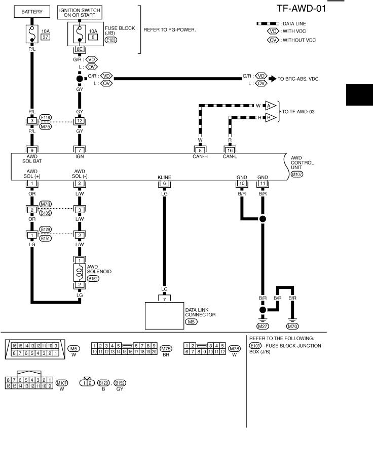
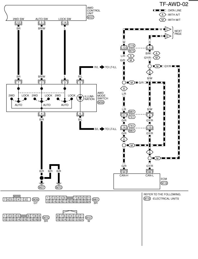
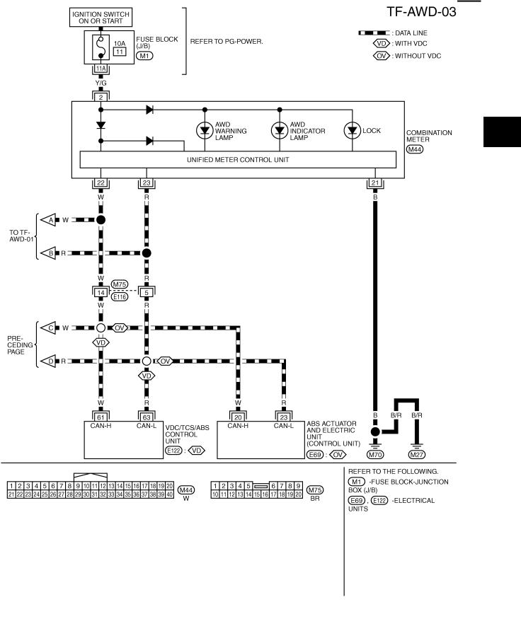
Wiring Diagram — AWD —
ADS0017F
A
B
C
TF
E
F
G
H
I
J
K
L
M
TDWB0002E
Revision: 2006 July |
TF-17 |
2006 X-Trail |
TROUBLE DIAGNOSIS
TDWB0053E
Revision: 2006 July |
TF-18 |
2006 X-Trail |
TROUBLE DIAGNOSIS
A
B
C
TF
E
F
G
H
I
J
K
L
M
TDWB0004E
Revision: 2006 July |
TF-19 |
2006 X-Trail |

TROUBLE DIAGNOSIS
Trouble Diagnosis Chart for Symptoms |
|
ADS0017G |
||
If AWD warning lamp turns ON, perform self-diagnosis. Refer to TF-23, "SELF-DIAG RESULTS MODE" . |
|
|||
Symptom |
Condition |
Check item |
Reference page |
|
|
|
|
|
|
AWD indicator lamp and LOCK indicator |
|
CAN communication line |
|
|
lamp do not turn ON for approx. 1 second |
|
|
|
|
|
Power supply and ground for AWD con- |
|
||
when ignition switch is turned to ON. |
Ignition switch: ON |
TF-37 |
||
trol unit |
||||
(AWD indicator lamp and LOCK indicator |
|
|
||
|
|
|
||
lamp check) |
|
Unified meter control unit |
|
|
|
|
|
|
|
AWD warning lamp does not turn ON when |
|
CAN communication line |
|
|
ignition switch is turned to ON. |
Ignition switch: ON |
|
TF-38 |
|
Unified meter control unit |
||||
(AWD warning lamp check) |
|
|
||
|
|
|
||
|
|
|
|
|
|
|
CAN communication line |
|
|
|
|
|
|
|
|
|
Power supply and ground for AWD con- |
|
|
|
|
trol unit |
|
|
|
|
|
|
|
AWD warning lamp does not turn OFF sev- |
Engine running |
Unified meter control unit |
TF-39 |
|
|
||||
eral seconds after engine started. |
|
|||
AWD solenoid |
||||
|
|
|||
|
|
|
||
|
|
|
|
|
|
|
AWD actuator relay (integrated in AWD |
|
|
|
|
control unit) |
|
|
|
|
|
|
|
|
|
Wheel sensor |
|
|
|
|
|
|
|
|
|
AWD mode switch |
|
|
AWD mode cannot be switched after engine |
|
|
|
|
Engine running |
CAN communication line |
TF-40 |
||
is started. |
||||
|
|
|
||
|
|
Unified meter control unit |
|
|
|
|
|
|
|
|
|
CAN communication line |
|
|
|
● While driving |
|
|
|
Heavy tight-corner braking symptom occurs |
AWD mode switch |
|
||
|
|
|||
● AUTO mode |
|
|
||
when vehicle is driven in AUTO mode and |
Accelerator pedal position signal |
TF-41 |
||
● Steering wheel is |
||||
steering wheel is turned fully to either side |
|
|||
AWD solenoid |
|
|||
after engine is started. (See NOTE.) |
turned fully to either |
|
||
|
|
|||
|
sides |
Mechanical malfunction of electric con- |
|
|
|
|
trolled coupling (clutch sticking etc.) |
|
|
|
|
|
|
|
|
|
AWD solenoid |
|
|
|
Vehicle speed: 10 km/h |
|
|
|
|
Mechanical malfunction of electric con- |
|
||
|
(6 MPH) or less |
|
||
|
trolled coupling (Mechanical engage- |
|
||
|
|
|
||
|
|
ment of clutch is not possible.) |
|
|
Vehicle does not enter AWD mode even |
|
|
|
|
|
Operating condition of parking brake |
TF-42 |
||
though AWD warning lamp turned to OFF. |
|
|||
|
|
|
||
|
Vehicle speed: 10 km/h |
AWD solenoid |
|
|
|
|
|
||
|
(6 MPH) or more |
Mechanical malfunction of electric con- |
|
|
|
|
trolled coupling (Mechanical engage- |
|
|
|
|
ment of clutch is not possible.) |
|
|
|
|
|
|
|
While driving, AWD warning lamp flashes |
● While driving |
Protection function is activated due to |
|
|
rapidly. (When flashing in approx. 1 minute |
heavy load to electric controlled cou- |
|
||
● AUTO mode and |
TF-43 |
|||
and then turning OFF.) |
pling. (AWD system is not malfunction- |
|||
LOCK mode |
|
|||
Rapid flashing: 2 times/second |
ing.) |
|
||
|
|
|||
|
|
|
|
|
While driving, AWD warning lamp flashes |
● While driving |
|
|
|
slowly. (When continuing to flash until turn- |
Tire size is different between front and |
|
||
● Vehicle speed: 20 km/h |
TF-43 |
|||
ing ignition switch OFF) |
rear of vehicle. |
|||
(12 MPH) or more |
|
|||
Slow flashing: 1 time/2 seconds |
|
|
||
|
|
|
||
|
|
|
|
|
NOTE: |
|
|
|
|
●Light tight-corner braking symptom may occur depending on driving conditions in AUTO mode. This is not malfunction.
●Heavy tight-corner braking symptom occurs when vehicle is driven in the following conditions: LOCK mode, steering wheel is turned fully to either side, and accelerator pedal was depressed.
Revision: 2006 July |
TF-20 |
2006 X-Trail |
TROUBLE DIAGNOSIS
AWD Control Unit Input/Output Signal Reference Values |
|
ADS0017H |
|||
AWD CONTROL UNIT INSPECTION TABLE |
|
|
|
||
Specifications with CONSULT-II |
|
|
|
||
|
|
|
|
|
|
Monitor item [Unit] |
Content |
Condition |
|
Display value |
|
|
|
|
|
|
|
|
|
Vehicle stopped |
|
0.00 km/h (0.00 mph) |
|
|
|
|
|
|
|
FR RH SENSOR [km/h] or [mph] |
Wheel speed (Front wheel |
Vehicle running |
|
Approximately equal to |
|
CAUTION: |
|
||||
right) |
|
||||
|
the indication on speed- |
||||
|
|
||||
|
|
Check air pressure of tire under |
|||
|
|
ometer (Inside of ± 10%) |
|||
|
|
standard condition. |
|
||
|
|
|
|
||
|
|
|
|
|
|
|
|
Vehicle stopped |
|
0.00 km/h (0.00 mph) |
|
|
|
|
|
|
|
FR LH SENSOR [km/h] or [mph] |
Wheel speed (Front wheel |
Vehicle running |
|
Approximately equal to |
|
CAUTION: |
|
||||
left) |
|
||||
|
the indication on speed- |
||||
|
|
||||
|
|
Check air pressure of tire under |
|||
|
|
ometer (Inside of ± 10%) |
|||
|
|
standard condition. |
|
||
|
|
|
|
||
|
|
|
|
|
|
|
|
Vehicle stopped |
|
0.00 km/h (0.00 mph) |
|
|
|
|
|
|
|
RR RH SENSOR [km/h] or [mph] |
Wheel speed (Rear wheel |
Vehicle running |
|
Approximately equal to |
|
CAUTION: |
|
||||
right) |
|
||||
|
the indication on speed- |
||||
|
|
||||
|
|
Check air pressure of tire under |
|||
|
|
ometer (Inside of ± 10%) |
|||
|
|
standard condition. |
|
||
|
|
|
|
||
|
|
|
|
|
|
|
|
Vehicle stopped |
|
0.00 km/h (0.00 mph) |
|
|
|
|
|
|
|
RR LH SENSOR [km/h] or [mph] |
Wheel speed (Rear wheel |
Vehicle running |
|
Approximately equal to |
|
CAUTION: |
|
||||
left) |
|
||||
|
the indication on speed- |
||||
|
|
||||
|
|
Check air pressure of tire under |
|||
|
|
ometer (Inside of ± 10%) |
|||
|
|
standard condition. |
|
||
|
|
|
|
||
|
|
|
|
|
|
BATTERY VOLT [V] |
Power supply voltage for |
Ignition switch: ON |
|
Battery voltage |
|
AWD control unit |
|
||||
|
|
|
|
||
|
|
|
|
||
|
|
When depressing accelerator pedal |
|
||
THRTL POS SEN [%] |
Throttle opening condition |
(Value rises gradually in response to |
0 - 100% |
||
|
|
throttle position.) |
|
|
|
|
|
|
|
|
|
|
|
|
2WD |
Approx. 0.000A |
|
|
|
Engine speed |
|
|
|
|
|
AUTO |
Approx. 0.000A |
||
|
|
: At idle |
|||
|
|
|
|
||
ETS SOLENOID [A] |
Monitored value of current at |
|
LOCK |
Approx. 0.000A |
|
|
|
|
|||
AWD solenoid |
|
|
|
||
Engine speed |
2WD |
Approx. 0.000A |
|||
|
|||||
|
|
||||
|
|
|
|
||
|
|
: 3,000 rpm or more con- |
AUTO |
Approx. 0.000 - 1.500A* |
|
|
|
stant |
|
|
|
|
|
LOCK |
Approx. 2.800A |
||
|
|
|
|||
|
|
|
|
|
|
STOP LAMP SW [ON/OFF] |
Condition of brake pedal |
Brake pedal: Depressed |
|
ON |
|
|
|
|
|||
operation |
|
|
|
||
Brake pedal: Released |
|
OFF |
|||
|
|
||||
|
|
|
|||
|
|
|
|
|
|
|
|
Engine stopped |
|
STOP |
|
|
|
(Engine speed: Less than 400 rpm) |
|||
ENG SPEED SIG [RUN/STOP] |
Condition of engine running |
|
|||
|
|
|
|||
Engine running |
|
RUN |
|||
|
|
|
|||
|
|
(Engine speed: 400 rpm or more) |
|||
|
|
|
|||
|
|
|
|
|
|
|
Operating condition of AWD |
Engine stopped (Ignition |
|
OFF |
|
|
switch: ON) |
|
|||
ETS ACTUATOR [ON/OFF] |
actuator relay (integrated in |
|
|||
|
|
||||
|
|
|
|||
|
AWD control unit) |
|
|
|
|
|
Engine running |
|
ON |
||
|
|
|
|||
|
|
|
|
|
|
4WD WARN LAMP [ON/OFF] |
AWD warning lamp condition |
AWD warning lamp: ON |
|
ON |
|
|
|
|
|||
AWD warning lamp: OFF |
|
OFF |
|||
|
|
|
|||
|
|
|
|
|
|
|
|
|
2WD |
2WD |
|
4WD MODE SW [2WD/AUTO/ |
Input condition from AWD |
|
|
|
|
AWD mode switch |
AUTO |
AUTO |
|||
LOCK] |
mode switch |
||||
|
|
|
|||
|
|
|
LOCK |
LOCK |
|
|
|
|
|
|
|
A
B
C
TF
E
F
G
H
I
J
K
L
M
Revision: 2006 July |
TF-21 |
2006 X-Trail |
Loading...