


XTrail T30 2006
Table of contents
 Loading...
GW-1
GLASSES, WINDOW SYSTEM & MIRRORS
I BODY
CONTENTS
C
D
E
F
G
H
J
K
L
M
SECTION GW
A
B
GW
Revision: 2006 July 2006 X-Trail
GLASSES, WINDOW SYSTEM & MIRRORS
PRECAUTIONS .......................................................... 3
Precautions for Supplemental Rest raint System
(SRS) “AIR BAG” and “SEAT BELT PRE-TEN-
SIONER” .................................................................. 3
Handling for Adhesive and Primer ........................... 3
PREPARATION ........................................................... 4
Special Service Tools ............................................... 4
Commercial Service Tools ........................................ 4
SQUEAK AND RATTLE TROUBLE DIAGNOSES ..... 5
Work Flow ................................................................ 5
CUSTOMER INTERVIEW ..................................... 5
DUPLICATE THE NOISE AND TEST DRIVE ....... 6
CHECK RELATED SERVICE BULLETINS .. ......... 6
LOCATE THE NOISE AND IDENTIFY THE
ROOT CAUSE ...................................................... 6
REP AIR THE CAUSE ........................................... 6
CONFIRM THE REPAIR ....................................... 7
Generic Squeak and Rattle Troubleshooting ........... 7
INSTRUMENT PANEL .......................................... 7
CENTER CONSOLE ............................................. 7
DOORS .............................. ................................... 7
TRUNK ............................... ................................... 8
SUNROOF/HEADLINING ..................................... 8
SEATS ................................................................... 8
UNDERHOOD .................... ............. ............. ......... 8
Diagnostic Worksheet .............................................. 9
WINDSHIELD GLASS AND MOLDING ....................11
Removal and Installation .........................................11
REMOVAL ............................................................11
INSTALLATION ................................................... 12
SIDE WINDOW GLASS ............................................ 13
Removal and Installation ........................................ 13
REMOVAL ........................................................... 13
INSTALLATION ................................................... 13
REPAIRING WATER LEAKS .............................. 14
BACK DOOR WINDOW GLASS .............................. 15
Removal and Installation ........................................ 15
REMOVAL ........................................................... 15
INSTALLATION ................................................... 16
REAR WINDOW DEFOGGER .................................. 17
Component Parts and Harness Connector Location ...17
System Description .................................................17
Wiring Diagram — DEF — .....................................19
T erminals and Reference Value for Smart Entrance
Control Unit .............................................................21
Work Flow ...............................................................21
Trouble Diagnoses ............................................. .... 21
Check Rear Window Defogger Relay Power Supply ...21
Check Smart Entrance Control Unit Power Supply
and Ground .............................................................23
Check Rear Window Defogger Switch Circuit ........24
Check Rear Window Defogger Circuit .................... 26
Check Door Mirror Defogger Circuit .......................27
Check Rear Window Defogger Indicator Lamp Cir-
cuit ............................... ...........................................29
Filament Check .................. ....... ...... ....... ...... ....... .... 31
Filament Repair ........... ...... ....... ...... ....... ...... ....... .... 31
REP AIR EQUIPMENT ......................................... 31
REP AIRING PROCEDURE ................................. 32
POWER WINDOW SYSTEM .................................... 33
Component Parts and Harness Connector Location ...33
System Description .................................................33
MANUAL OPERATION ........................................ 34
AUTO OPERATION .............................................37
POWER WINDOW LOCK ................................... 37
TIMER FUNCTION ..............................................37
DRIVER WINDOW ANTI–PINCH FUNCTION .... 37
Schematic .................... ....................................... ....38
Wiring Diagram – WINDOW – ................................ 39
Terminal and Reference Value for Power Window
Main Switch ............................................................ 43
Trouble Diagnoses Symptom Chart .......................44
Check Power Window Relay Power Supply and
Ground Circuit ........................................................45
Check Power Window Main Switch Power Supply
and Ground Circuit .................................................46
Check Power Window Motor (Driver Side) Circuit ...46
Check Power Window Motor Circuit ....................... 47
Check Power Window Switch Circuit ......................48
Check Power Window (Passenger Side) Circuit ....49

GW-2
Revision: 2006 July 2006 X-Trail
Check Power Window (Rear LH) Circuit ................. 49
Check Power Window (Rear RH) Circuit ................50
Check Limit Switch Circuit ......................................51
Check Encoder Circuit ............................................52
Check Door Switch Circuit ...................................... 54
FRONT DOOR GLASS AND REGULATOR .............56
Removal and Installation ........................................56
FRONT DOOR GLASS .......................................56
FRONT DOOR REGULATOR ASSEMBLY .........57
Fitting Inspection ....................................................58
REAR DOOR GLASS AND REGULATOR ...............59
Removal and Installation ........................................59
REAR DOOR GLASS .......................................... 59
REAR DOOR REGULATOR ASSEMBL Y ............61
Fitting Inspection .....................................................61
DOOR MIRROR . ...... ....... ...... ....... ...... ....... ...... ....... ....63
Wiring Diagram — MIRROR — ..............................63
Removal and Installation .........................................64
REMOVAL ........................................................ ....64
INSTALLATION ................................................ ....64
Disassembly and Assembly ................... ...... ....... ....65
DISASSEMBLY ................................................ ....65
ASSEMBLY ...................................................... ....66
INSIDE MIRROR .......................................................67
Removal and Installation .........................................67
REMOVAL ........................................................ ....67
INSTALLATION ................................................ ....67

PRECAUTIONS
GW-3
C
D
E
F
G
H
J
K
L
M
A
B
GW
Revision: 2006 July 2006 X-Trail
PRECAUTIONS PFP:00001
Precautions for Supplemental Restraint System (SRS) “AIR BAG” and “SEAT
BELT PRE-TENSIONER”
AIS005Q1
The Supplemental Rest raint System such as “AIR BAG” and “SEAT BELT PRE-TENSIONER”, used al ong
with a front seat belt, helps to redu ce th e risk or se verit y of i njury to the driv er and front passenge r for ce rtain
types of col lision. Information necessary to service the system safely is includ ed in the SRS a nd SB section of
this Service Manual.
WARNING:
● To avoid rendering the SRS inopera tive, whi ch could incr ease the risk of pe rsonal injury or death
in the event of a collision which would result in air bag inflation, all maintenance must be per-
formed by an authorized NISSAN/INFINITI dealer.
● Improper maintenance, inc luding incorrect removal and installation of the SRS, can lead to per-
sonal injury ca use d by unintentional ac tiv atio n of the system. F or r e mo va l o f Spi ral Cable and Air
Bag Module, see the SRS sec tion.
● Do not use electrical test equ ipment o n any circu it related to the SRS unless in structed to in this
Service Manual. SRS wiring harnesses can be id entified by yellow and/or orange harnesses or
harness connectors.
Handling for Adhesive and Primer AIS0061X
● Do not use an adhesive which is past its usable date. Shelf life of this product is limited to six months after
the date of manufacture. Carefully adhere to the expiration or manufacture date printed on the box.
● Keep primers and adhesive in a cool, dry place. Ideally, they should be stored in a refrigerator.
● Open the seal of the primer and adhesive just before application. Discard the remainder.
● Before applicat ion, be sure to shake the primer container to stir the contents. If any floating material is
found, do not use it.
● If any primer o r adhe sive co ntacts the sk in, wi pe it off with gasol ine or eq uivalen t and wash the skin w ith
soap.
● When using primer and adhesive, always observe the precautions in the instruction manual.

GW-4
PREPARATION
Revision: 2006 July 2006 X-Trail
PREPARATION PFP:00002
Special Service Tools AIS0061Z
The actual shapes of Kent-Moore tools may differ from those of special service tools illustrated here.
Commercial Service Tools AIS005Q3
Tool number
(Kent-Moore No.)
Tool name
Description
(J-39570)
Chassis ear
Locating the noise
(J-43980)
NISSAN Squeak and
Rattle Kit
Repairing the cause of noise
SIIA0993E
SIIA0994E
Tool name Description
Engine ear Locating the noise
Suction lifter
Remove the windshield,
back door window glass
Holding the door glass
SIIA0995E
PIIB1805J
SQUEAK AND RATTLE TROUBLE DIAGNOSES
GW-5
C
D
E
F
G
H
J
K
L
M
A
B
GW
Revision: 2006 July 2006 X-Trail
SQUEAK AND RATTLE TROUBLE DIAGNOSES PFP:00000
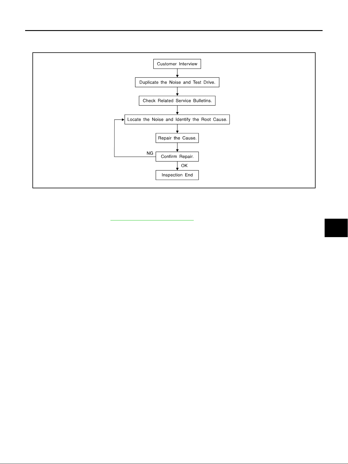
Work Flow AIS00611
CUSTOMER INTERVIEW
Interview the customer if possible, to determine the conditions that exist when the noise occurs. Use the Diag-
nostic Worksheet during the interview to docume nt the facts and conditions w hen the noise occurs and an y
customer's comments; refer to GW-9, "
Diagnostic Worksh eet " . This info rmatio n is n ecess ary to dupl icate the
conditions that exist when the noise occurs.
● The customer may not be able to provide a detailed description or the location of the noise. Attempt to
obtain all the facts and conditions that exist when the noise occurs (or does not occur).
● If there is more than one noise in the vehicle, be sure to diagnose and repair the noise that the customer
is concerned about. This can be accomplished by test driving the vehicle with the customer.
● After ident if yi ng th e t y pe of no is e, i so lat e th e no is e in t er ms o f i t s c ha r ac te ris t ic s. T he n oi se c ha ract e ris ti cs
are provided so the customer, service adviser and technician are all speaking the same language when
defining the noise.
● Squeak —(Like tennis shoes on a clean floor)
Squeak charact eristics include the lig ht contact/fast movement/ brought on by road condi tions/hard sur-
faces=higher pitch noise/softer surfaces=lower pitch noises/edge to surface=chirping
● Creak—(Like walking on an old wooden floor)
Creak characteristics include firm contact/slow movement/twisting with a rotational movement/pitch
dependent on materials/often brought on by activity.
● Rattle—(Like shaking a baby rattle)
Rattle charact eristics inclu de the f ast repe ated co ntact/vibra tion or similar mov ement/l oose parts/mi ssing
clip or fastener/incorrect clearance.
● Knock —(Like a knoc k on a door)
Knock characteristics include hollow sounding/sometimes repeating/often brought on by driver action.
● Tick —(Like a clock second hand)
Tick characteristics include gentle contacting of light materials/loose components/can be caused by driver
action or road co nditions.
● Thump—(Hea vy, muffled knock noise)
Thump characteristics include softer knock/d ead sound often brought on by activity.
● Buzz—(Like a bumble bee)
Buzz characteristics include high freque ncy rattle/firm contact.
● Often the de gree of acceptable nois e level will vary d epending upon the person. A noise that you may
judge as acceptable may be very irritating to the custome r.
● Weather conditions, especially humidit y and temperature, may have a great effect on noise level.
SBT842

GW-6
SQUEAK AND RATTLE TROUBLE DIAGNOSES
Revision: 2006 July 2006 X-Trail
DUPLICATE THE NOISE AND TEST DRIVE
If possible, drive the vehicle with the customer until the noise is duplicated. Note any additional information on
the Diagnostic Worksheet regarding the con ditions or location of the noise. This inform ation can be used to
duplicate the same conditions when you confirm the repair.
If the noise can be duplicated easily during the test drive, to help identify the source of the noise, try to dupli-
cate the noise with the vehicle stopped by doin g one or all of the following:
1) Close a door.
2) Tap or push/pull around th e area where the noise appears to be coming from.
3) Rev the engine.
4) Use a floor jack to recreat e vehicle “twist”.
5) At idl e, apply engine load (electrical load, half- c lutch on M/T models, drive position on A/T models).
6) Raise the vehicle on a hoist and hit a tire with a rubber hamme r.
● Drive the vehicle and attempt to duplicate the conditions the customer states exist when the noise occurs.
● If it is difficult to duplicate the nois e, drive th e vehic le slowly on an und ulating or ro ugh road t o stress the
vehicle body.
CHECK RELATED SERVICE BULLETINS
After verifying the customer concern or symptom, check ASIST for Technical Service Bulletins (TSBs) related
to that concern or symptom.
If a TSB relates to the symptom, follow the pr ocedure to repair the nois e.
LOCATE THE NOISE AND IDENTIFY THE ROOT CAUSE
1. Narrow down the nois e to a general area. To help pinpoint the source of the noise, use a lis tening tool
(Chassis Ear: J-39570, Engine Ear and mechanics stethoscope).
2. Narrow down the noise to a more specific area and identify the cause of the noise by:
● removing the components in the area that you suspect the noise is coming from.
Do not use too much force when remo ving clip s an d fa stener s, o ther wise c lip s a nd fa stener can be br oken
or lost during the repair, resulting in the creation of new noise.
● tapping or pushing/pulling the component that you suspect is causing the noise.
Do not tap or pus h/pull the com ponent with ex cessive force, otherwise the noise will b e eliminated on ly
temporarily.
● feeling for a vibration with your hand by touching the component(s) that you suspect is (are) causing the
noise.
● placing a piece of paper between components that you suspect are causing the noise.
● looking for loose components and cont act marks.
Refer to GW-7, "
Generic Squeak and Rattl e Troubles ho oti ng " .
REPAIR THE CAUSE
● If the cause is a loose component, tighten the component secur ely.
● If the cause is insufficient clearance between components:
– separate components by repositioning or loosening and retightening the component, if possible.
– insulate components with a suitable insulator such as urethane pads, foam blocks, felt cloth tape or ure-
thane tape. A Niss an Squeak a nd Rattl e Kit (J-439 80) is avai lable thro ugh your authorized Nissan Pa rts
Department.
CAUTION:
Do not use excessive force as many components are constructed of plastic and may be damaged.
NOTE:
Always check with the Parts Department for the latest parts information.
The following materials are contained in the Nissan Squeak and Rattle Kit (J-43980). Each item can be
ordered separately as needed.
URETHANE PADS [1.5 mm (0.059 in) thick]
Insulates connectors, harness, etc.
76268-9E005: 100 × 135 mm (3.94 × 5.31 in)/76884-71L01: 60 × 85 mm (2.36 × 3.35 in)/76884-
71L02: 15 × 25 mm (0.59 × 0.98 in)
INSULATOR (Foam blocks)
Insulates components from contact. Can be used to fill space behind a panel.
73982-9E000: 45 mm (1.77 in) thick, 50 × 50 mm (1.97 × 1.97 in)/73982-
50Y00: 10 mm (0.39 in) thick, 50 × 50 mm (1.97 × 1.97 in)

SQUEAK AND RATTLE TROUBLE DIAGNOSES
GW-7
C
D
E
F
G
H
J
K
L
M
A
B
GW
Revision: 2006 July 2006 X-Trail
INSULATOR (Light foam block)
80845-71L00: 30 mm (1.18 in) thick, 30 × 50 mm (1.18 × 1.97 in)
FELT CLOTHTAPE
Used to insulate where movement does not occur. Ideal for instrum ent panel applications.
68370-4B000: 15 × 25 mm (0.59 × 0.98 in) pad/68239-13E00: 5 mm (0.20 in) wide tape roll
The following materials, not found in the kit, can also be used to repair squeaks and rattles.
UHMW (TEFLON) TAPE
Insulates where slight movement is present. Ideal for instrument panel applications.
SILICONE GREASE
Used in place of UHMW tape that will be visible or not fit. Will only last a few months.
SILICONE SPRAY
Use when greas e cannot be applied.
DUCT TAPE
Use to elimin ate movement.
CONFIRM THE REPAIR
Confirm that the cause of a noise is repaired by test driving the vehicle. Operate the vehicle under the same
conditions as when the noise originally occurred. Refer to the notes on the Diagnostic Worksheet.
Generic Squeak and Rattle Troubleshooting AIS00612
Refer to Table of Contents for specific comp on en t rem ov al and in stalla tion information.
INSTRUMENT PANEL
Most incidents are caused by contact and movement between:
1. The cluster lid A and instrument panel
2. Acrylic lens and combination meter hous ing
3. Instrument panel to front pillar garnish
4. Instrument panel to windshield
5. Instrument panel mounting pins
6. Wiring harnesses behind the combination meter
7. A/C defroster duct and duct joint
These incidents can usually be located by tapping or moving the components to duplicate the noise or by
pressing on the co mponents while drivi ng to s t op th e no is e. Most of these in c ide nts c an be re paired by apply-
ing felt cloth tape or silicon spray (in hard to reach areas). Urethane pads can be used to insulate wiring har-
ness.
CAUTION:
Do not use silicone s pray to isolate a sq ueak or rattle. If you saturate the area with silicone, you w ill
not be able to recheck the repair.
CENTER CONSOLE
Components to pay attention to include:
1. Shifter assembly cover to finisher
2. A/C control unit and clust er lid C
3. Wiring harnes se s be hin d audio and A/C control unit
The instrument panel repair and isolation procedures also apply to the center console.
DOORS
Pay attention to the:
1. Finisher and inner panel making a slapping noise
2. Inside handle escutcheon to door finisher
3. Wiring harnesses tapping
4. Door striker out of alignment causing a popping noise on starts and stops
Tapping or moving the components or pressing on them while driving to duplicate the conditions can isolate
many of these incidents. You can usually insulate the areas with felt cloth tape or insulator foam blocks from
the Nissan Squeak and Rattle Kit (J-43980) to repair the noise.

GW-8
SQUEAK AND RATTLE TROUBLE DIAGNOSES
Revision: 2006 July 2006 X-Trail
TRUNK
Trunk noises are often caused by a loose jack or loose items put into the trun k by the owner.
In addition look for:
1. T runk lid dumpers out of adjustment
2. T runk lid striker out of adjustment
3. The trunk lid torsion bars knocking together
4. A loose l icense plate or b racket
Most of these incidents can be repaired by adjusting, securing or insulating the item(s) or compo nent(s) caus-
ing the noise.
SUNROOF/HEADLINING
Noises in the sunroof/headlining area can often be traced to one of the following:
1. Sunroof lid, rail, linkage or seals making a rattle or light knocking noise
2. Sunvisor shaft shaking in the holder
3. Front or rear windshiel d touching headlining and squeaking
Again, pressing on the components to stop the noise while duplicating the conditions can isolate most of these
incidents. Repairs usually consist of insulating with felt cloth tape.
SEATS
When isolatin g seat no ise it 's imp ort ant to not e the p ositi on th e seat is in and t he loa d plac ed on t he sea t when
the noise is present. These conditions should be duplicated when verifying and isolating the cause of the
noise.
Cause of seat noise include:
1. Headrest rods and holder
2. A squeak between the seat pad cushion and frame
3. The rear seatback lock and bracket
These noises can be isolated by moving or pressing on the suspected components while duplicating the con-
ditions under wh ic h th e n ois e oc cu rs. Most of these in ci de nts ca n b e re pair ed by rep os iti on in g th e c om po ne nt
or applying urethane tape to the contact area.
UNDERHOOD
Some interior noi se may be caus ed by componen ts under the hood or o n the engine wall . The noise is th en
transmitted into the passenger compartment.
Causes of transmitted underhood noise include:
1. Any component mounted to the engine wall
2. Compon ents that pass through the engine wall
3. Engine wall mounts and connectors
4. Loose radiator moun tin g pi ns
5. Hood bumpers out of adjus tm e nt
6. Hood striker out of adjustment
These noises can be difficu lt to isol ate sin ce the y cann ot be rea ched from the inter ior of the ve hi cle. The best
method is to sec ure, mov e or insul ate one com ponen t at a time and test drive the vehicle . Also , engine RPM
or load can be cha nged to isol ate the noise. Repairs can usu ally be made by moving, adj usting, securing, or
insulating the component causing the noise.

SQUEAK AND RATTLE TROUBLE DIAGNOSES
GW-9
C
D
E
F
G
H
J
K
L
M
A
B
GW
Revision: 2006 July 2006 X-Trail
Diagnostic Worksheet AIS00613
PIIB0723E

GW-10
SQUEAK AND RATTLE TROUBLE DIAGNOSES
Revision: 2006 July 2006 X-Trail
SBT844

WINDSHIELD GLASS AND MOLDING
GW-11
C
D
E
F
G
H
J
K
L
M
A
B
GW
Revision: 2006 July 2006 X-Trail
WINDSHIELD GLASS AND MOLDING PFP:72700
Removal and Installation AIS005Q7
REMOVAL
1. Remove the front pillar garnish and the headlining. Refer to EI-36, "BODY SIDE TRIM" and EI-40,
"HEADLINING" .
2. Partially remove the roof rail. Refer to EI-27, "
ROOF RAIL" .
3. Remove the cowl top cover. Refer to EI-19, "
COWL TOP" .
4. Apply a protective tape around the windshield glass to protect the painted surface from damage.
5. Cut the wind shield molding with a cutting knife.
After removing mo ldings using pliers, remove glass using piano wire or p ower cutting tool and an inflatabl e
pump bag.
● If a windshield glass is to be re used, mark the body and the glass with mating marks.
WARNING:
When cutting the glass from the vehicl e, always wear safety glasses and heavy gloves to help prevent
glass splinters from entering your eyes or cutting your hands.
CAUTION:
● When a windshield glass is to be reused, do not use a cutting knife or power cutting tool.
● Be careful not to scratch the glass when removing.
● Do not set or stand the glass on its edge. Small chips may develop into cracks.
6. Remove the windshield glass, using suction lifter.
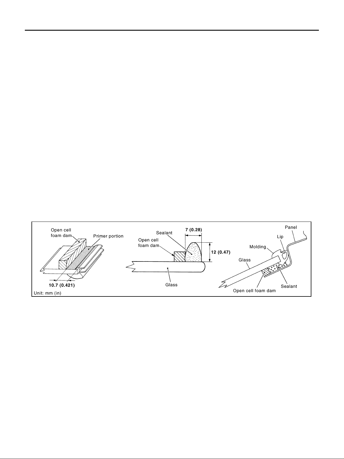
1. Windshield molding 2. Windshield glass 3. Open cell foam dam
4. Spacer
PIIB1640E
PIIA0186E
GW-12
WINDSHIELD GLASS AND MOLDING
Revision: 2006 July 2006 X-Trail
INSTALLATION
● Use a genuine Nissan Urethane Adhesive Kit (if available) or equivalent and follow the instructions fur-
nished with it.
● While the urethane ad hesi ve is curing , open a door wi nd ow. This will prevent t he glass from b eing fo rced
out by passenger compartment air pressure when a door is cl osed.
● The molding must be installed securely so that it is in position and leaves no gap.
● Inform the customer that the vehicle should remain stationary until the urethane adhesive has completely
cured (preferably 24 hours). Curing time varies with temperature and humidity.
WARNING:
● Keep heat and open flames away as primers and adhesive are flammable.
● The materials contained in the kit are ha rmful if swallowe d, and may irritate skin and eye s. Avoid
contact with the skin and eyes.
● Use in an open, well ventilated location. Avoid breathing the vapors. They can be harmful if
inhaled. If affected by vapor inhalation, immediately move to an area with fresh air.
● Driving the vehicle before the urethane adhesive has completely cured may affect the perfor-
mance of the windshield in case of an accident.
CAUTION:
● Do not use an adhesive which is past its usable term. Shelf life of this p roduct is limited to six
months after the date of manufacture. Carefully adhere to the expiration or manufacture date
printed on the box.
● Keep primers and adhesive in a cool, dry place. Ide ally, they should be stored in a refrigerator.
● Do not leave primers or adhesive cartridge unattended with their caps open or off.
● The vehicle should not be driven for at least 24 hours or u ntil the urethane adhesive has c om-
pletely cured. Curing time varies dependin g on temperature and humidity. The curing time will
increase under lower temperature and lower humidity.
Repairing Water Leaks
Leaks can be repaired without removing and reinstalling glass.
If water is leaking between the urethane adhesive material and body or glass, determine the extent of leakage.
This can be done by applying water to the windshield area while pushing glass outward.
To stop the leak, apply primer (if necessary) and then urethane adhesive to the leak point.
PIIB1641E
SIDE WINDOW GLASS
GW-13
C
D
E
F
G
H
J
K
L
M
A
B
GW
Revision: 2006 July 2006 X-Trail
SIDE WINDOW GLASS PFP:83300
Removal and Installation AIS005Q8
REMOVAL
1. Remove luggage side lower finisher and rear pillar finisher. Refer to EI-36, "BODY SIDE TRIM" .
2. Apply protective tap e on body panels around side window glass to protect painted surfaces fr om damage.
● Remo ve glass using pian o wire or power cutting tool and an
inflatable pump bag.
● If a side window glass is to be reused, mark the body and the
glass with mating marks.
WARNING:
When cutting the glass from the vehicle, always wear safety
glasses and heavy gloves to help prevent glass splinters
from entering your eyes or cutting your hands.
CAUTION:
● Be careful not to scratch the glass when removing.
● Do not set or stand the glass on its edge. Small chips
may develop into cracks.
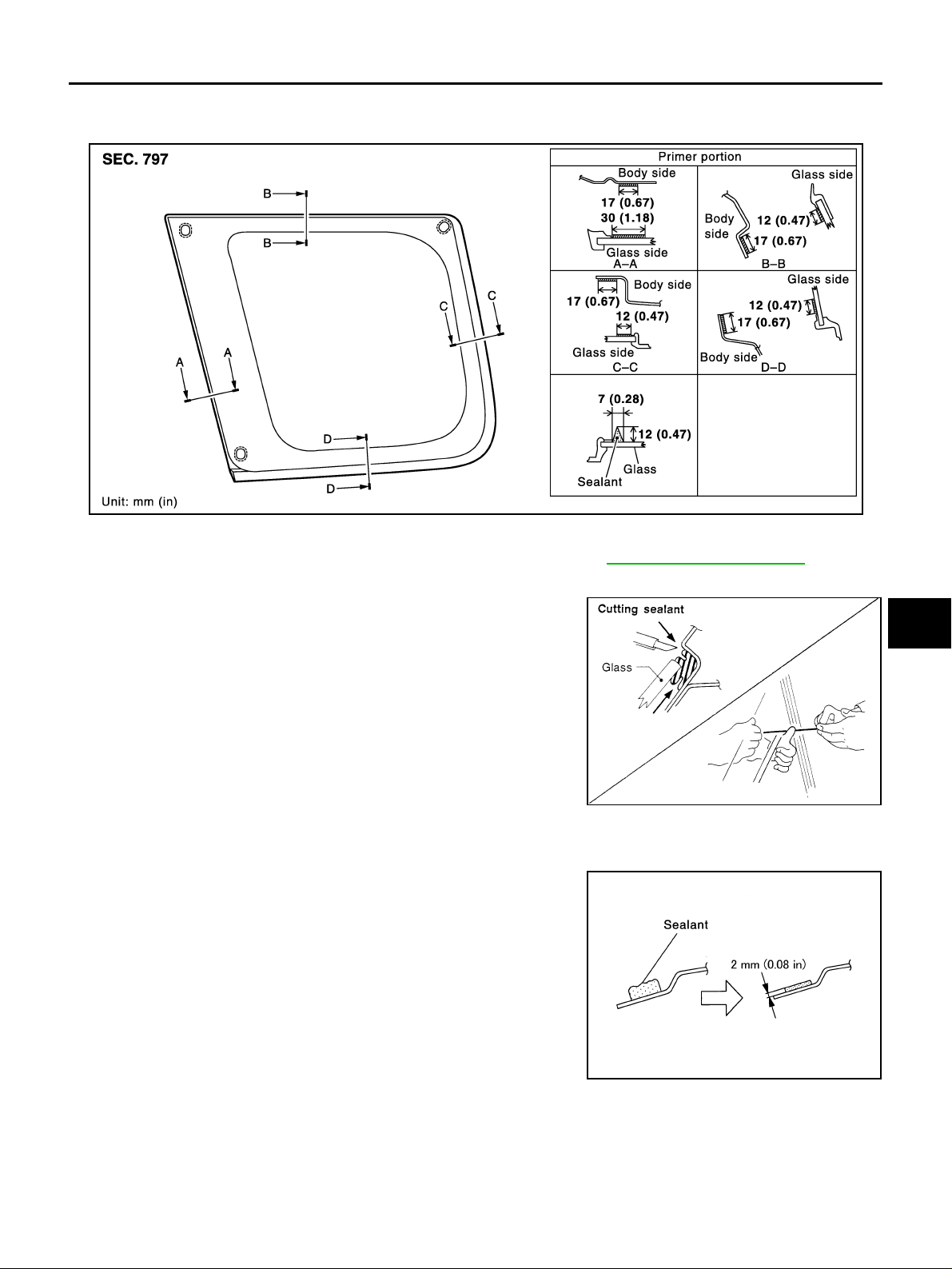
INSTALLATION
● With a knife, scrape off remaining adhesive left around on the
side of vehicle body to as thin and flat as 2 mm (0.08 in).
● Use a genuine Nissa n Urethane Adhesive Kit (if av ailable) or equivalent and fol low the instructions fur-
nished with it.
● While the uretha ne adh esiv e is curi ng, op en a do or win dow. This will prevent th e glas s from bein g force d
out by passenger compartment air pressure when a door is closed.
● The molding must be installed securely so that it is in position and leaves no gap.
SIIA0168E
SBF034B
SIIA1097E

GW-14
SIDE WINDOW GLASS
Revision: 2006 July 2006 X-Trail
● Inform the customer that the vehicle should remain stationary unit the urethane adhesive has completely
cured (preferably 24 hours). Curing time varies with temperature and humidity.
WARNING:
● Keep heat and open flames away as primers and adhesive are flammable.
● The materials contained in the Kit are ha rmful if swall owed, an d may irritate skin and eye s. Avoid
contact with the skin and eyes.
● Use in an open, well ventilated location. Avoid breathing the vapors. They can be harmful if
inhaled. if affected by vapor inhalation, immediately move to an area with fresh air.
● Driving the vehicle before the urethane adhesive has completely cured may affect the perfor-
mance of the side window in case of an accident.
CAUTION:
● Do not use an adhesive which is past its usable term. Shelf life of this p roduct is limited to six
months after the date of manufacture. Carefully adhere to the expiration or manufacture date
printed on the box.
● Keep primers and adhesive in a cool, dry place. Ide ally, they should be stored in a refrigerator.
● Do not leave primers or adhesive cartridge unattended with their caps open or off.
● The vehicle should not be driven for at least 24 hours or u ntil the urethane adhesive has c om-
pletely cured. Curing time varies dependin g on temperature and humidity. The curing time will
increase under lower temperature and lower humidity.
REPAIRING W ATER LEAKS
Leaks can be repaired without removing and reinstalling glass.
If water is le akin g bet ween t he u retha ne ad hesi ve mate ria l and body or glas s, de termi ne t he ex tent of lea kage .
This can be done by applying water to the side window area while pushing glass outward.
To stop the leak, apply primer (if necessary) and then urethane adhesive to the leak point.
BACK DOOR WINDOW GLASS
GW-15
C
D
E
F
G
H
J
K
L
M
A
B
GW
Revision: 2006 July 2006 X-Trail
BACK DOOR WINDOW GLASS PFP:90300
Removal and Installation AIS005Q9
REMOVAL
1. Remove rear wiper arm. Refer to WW-14, "Removal and Installation of Rear Wiper Arms, Adjustment for
Wiper Arms Stop Lo cation" .
2. Remove rear w asher nozzle. R efer to WW- 16, "
Removal and Installatio n of Rear Wa sher Nozzle" .
3. Remove rear window defogger connectors.
4. Remove high-mounted stop lamp. Refer to LT-34, "Removal and Installa tion of High-M ounted Stop Lamp"
5. Apply a protective tape around the back door window glass to prevent the painted surface from being
damaged.
6. Cut adhesive using piano wire or power cutting tool and an inflatable pump bag.
● If a back door window glass is to be reused, mark the body and the glass with matching marks.
WARNING:
When cutting the glass from the vehicl e, always wear safety glasses and heavy gloves to help prevent
glass splinters from entering your eyes or cutting your hands.
CAUTION:
● When a back door window glass is to be reused, do not use a cutting knife or power cutting tool.
● Be careful not to scratch the glass when removing.
PIIB0582E

GW-16
BACK DOOR WINDOW GLASS
Revision: 2006 July 2006 X-Trail
● Do not set or stand t he glass on its edge. Small chips ma y develop into cracks.
7. Remove the back door window glass, using suction lifter.
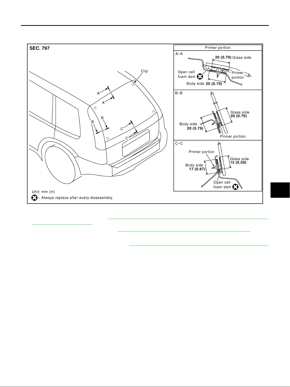
INSTALLATION
● With a knife, scrape off remaining adhesive left around on the
side of vehicle body to as thin and flat as 2 mm (0.08 in).
● Use a genuine Nissan Urethane Adhesive Kit (if available) or
equivalent and follow the instructions furnished with it.
● While the uret hane adhe sive is curi ng, open a doo r wind ow. This
will prevent the gl ass from being forced out by pas senger com-
partment air pressure when a door is closed.
● Inform the customer that the vehicle should remain stationary
until the urethane adhesive has completely cured (preferably 24
hours). Curing time varies wi th temperature and humidity.
WARNING:
● Keep heat and open flames away as primers and adhesive are flammable.
● The materials contained in the kit are ha rmful if swallowe d, and may irritate skin and eye s. Avoid
contact with the skin and eyes.
● Use in an open, well ventilated location. Avoid breathing the vapors. They can be harmful if
inhaled. If affected by vapor inhalation, immediately move to an area with fresh air.
● Driving the vehicle before the urethane adhesive has completely cured may affect the perfor-
mance of the back door window in case of an accident.
CAUTION:
● Do not use an adhesive which is past its usable term. Shelf life of this p roduct is limited to six
months after the date of manufacture. Carefully adhere to the expiration or manufacture date
printed on the box.
● Keep primers and adhesive in a cool, dry place. Ide ally, they should be stored in a refrigerator.
● Do not leave primers or adhesive cartridge unattended with their caps open or off.
● The vehicle should not be driven for at least 24 hours or u ntil the urethane adhesive has c om-
pletely cured. Curing time varies dependin g on temperature and humidity. The curing time will
increase under lower temperature and lower humidity.
PIIB0415E
SIIA1097E
REAR WINDOW DEFOGGER
GW-17
C
D
E
F
G
H
J
K
L
M
A
B
GW
Revision: 2006 July 2006 X-Trail
REAR WINDOW DEFOGGER PFP:25350
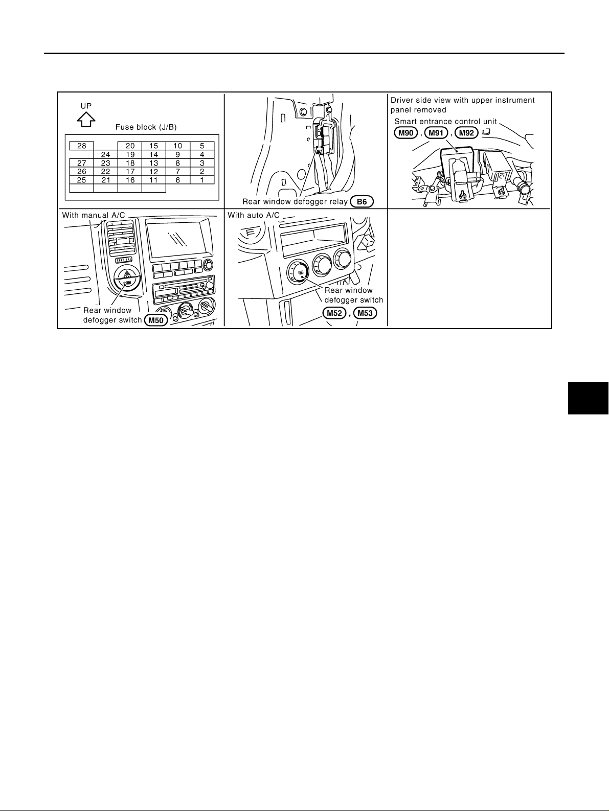
Component Parts and Harness Connector Location AIS005QA
System Description AIS0062J
The rear window defogger system is controlled by smart entrance control unit.The rear window defogger oper-
ates only for approximately 15 minutes.
Power is supplied at all times
● through 20A fuse [No.25, located in the fuse block (J/B)]
● to rear window defogger relay terminal 3
● through 10A fuse [No.27, located in the fuse block (J/B)]
● to rear window defogger relay terminal 6 (with door mirror defogger)
● through 10A fuse [No.26, located in the fuse block (J/B)]
● to smart entrance control unit terminal 49
With the ignition switch in the ON or START position,
Power is supplied
● through 10A fuse [No.5, located in the fuse block (J/B)]
● to rear wind ow defogger relay terminal 1 and
● to smart entrance control unit terminal 27.
Ground is supplied
● to smart entrance control unit terminals 43 and 64
● through body groun d M2 7 an d M7 0.
● to rear window defogger switch terminals 2 and 4 (with manual A/C) or
● to A/C auto amp. terminal 3 (with auto A/C)
● through body groun d M2 7 an d M7 0.
When the rear window defogger switch is turned ON,
Ground is supplied
● to smart entrance control unit terminal 14
● through rear window defogge r switch 1 (with manual A/C) or
● through A/C auto amp. terminal 22 (with auto A/C)
Terminal 37 of the smart entrance control unit then supplies ground to the rear window defogger relay terminal
2.
With power and ground supplied, the rear window defogger relay is energized.
Power is supplied
● through rear window defogger relay terminal 5 and 7
PIIB1607E

GW-18
REAR WINDOW DEFOGGER
Revision: 2006 July 2006 X-Trail
● to the rear window defogger and door mirror defogger.
The rear window defogger has an independent ground.
With power and ground supplied, the rear window defogger filaments heat and defog the rear window.
When the system is activated, the rear window defogger indicator illuminates in the rear window defogger
switch.
Power is supplied
● through rear window defogger relay terminal 5
● to rear window defogger switch terminal 3 (with manual A/C) or
● to A/C auto amp. terminal 23 (with auto A/C).

REAR WINDOW DEFOGGER
GW-19
C
D
E
F
G
H
J
K
L
M
A
B
GW
Revision: 2006 July 2006 X-Trail
Wiring Diagram — DEF — AIS005QD
TIWB0677E

GW-20
REAR WINDOW DEFOGGER
Revision: 2006 July 2006 X-Trail
TIWB0067E

REAR WINDOW DEFOGGER
GW-21
C
D
E
F
G
H
J
K
L
M
A
B
GW
Revision: 2006 July 2006 X-Trail
Terminals and Reference Value for Smart Entrance Control Unit AIS005QF
Work Flow AIS0062Q
1. Check the symptom and customer's requests.
2. Understand the outline of system. Refer to GW-17, "
System Description"
3. According to th e trouble diagno sis cha rt, repair or r eplace the cause o f the mal functio n. Refer to GW-21,
"Trouble Diagnoses"
4. Does rear window defogger operate normally? YES: GO TO 5, NO: GO TO 3.
5. INSPECTION END.
Trouble Diagnoses AIS0062K
● Make sure that ot her systems using the signal of the following systems operate normally .
Check Rear Window Defogger Relay Power Supply AIS0062R
1. CHECK FUSE
● Check 10A fuse [No. 5, located in the fuse block (J/B)]
● Check 10A fuse [No. 27, located in the fuse block (J/B)]
● Check 20A fuse [No. 25, located in the fuse block (J/B)]
NOTE:
Refer to GW-17, "
Component Parts and Harness Connector Location"
OK or NG
OK >> GO TO 2.
NG >> If fuse is blown, be sure to eliminate cause of malfunction before installing new fuse. Refer to PG-
2, "POWER SUPPLY ROUTING"
TERMINAL
WIRE
COLOR
ITEM CONDITION
VOLTAGE (V)
(Approx.)
14 LG/B Rear window defogger switch signal
Rear window
defogger switch
: ON 0
: OFF Battery voltage
27 G Ignition switch ON
Ignition switch position
(ON or START)
Battery voltage
37 G/W Rear window defogger relay control signal
Rear window
defogger switch
: ON 0
: OFF Battery voltage
43 B Ground — 0
49 L/R Power source (Fuse) — Battery voltage
64 B Ground — 0
Symptom Diagnoses / Service procedure Refer to page
Rear window defogger and door mirror defogger
does not operate.
1. Check rear window defogger relay power supply GW-21
2.
Check smart entrance control unit power supply and
ground
GW-23
3. Check rear window defogger switch ci rc uit GW-24
Rear window defogger alone does not oper at e. 1. Check rear window def ogger circuit GW-26
Door mirror defogger alone does not operate . 1. Check door mirror defogge r circ uit GW-27
Rear window defogger switch does not light, but
rear window defogger operates.
1. Check rear window defogger indicator lamp ci rc ui t GW-29
Loading...