


 Loading...
C TRANSMISSION/TRANSAXLE
SECTION AT
AUTOMATIC TRANSAXLE
CONTENTS
A
B
AT
D
E
INDEX FOR DTC ....................................................... |
5 |
Alphabetical Index ................................................... |
5 |
DTC No. Index ........................................................ |
6 |
PRECAUTIONS ......................................................... |
7 |
Precautions for Supplemental Restraint System |
|
(SRS) “AIR BAG” and “SEAT BELT PRE-TEN- |
|
SIONER” ................................................................. |
7 |
PrecautionsforOnBoardDiagnostic(OBD)System |
|
of A/T and Engine ................................................... |
7 |
Precautions ............................................................. |
7 |
Service Notice or Precautions ................................. |
9 |
PREPARATION ........................................................ |
10 |
Special Service Tools ............................................ |
10 |
Commercial Service Tools ..................................... |
14 |
A/T FLUID ................................................................ |
16 |
Checking A/T Fluid ................................................ |
16 |
Changing A/T Fluid ............................................... |
17 |
A/T Fluid Cooler Cleaning ..................................... |
17 |
A/T CONTROL SYSTEM ......................................... |
20 |
Cross-sectional View ............................................. |
20 |
Shift Mechanism .................................................... |
21 |
TCM Function ........................................................ |
30 |
CAN Communication ............................................. |
31 |
Input/Output Signal of TCM ................................... |
31 |
Line Pressure Control ........................................... |
32 |
Shift Control .......................................................... |
33 |
Lock-up Control ..................................................... |
34 |
Engine Brake Control (Overrun Clutch Control) .... |
35 |
Control Valve ......................................................... |
37 |
ON BOARD DIAGNOSTIC (OBD) SYSTEM ........... |
38 |
Introduction ........................................................... |
38 |
OBD-II Function for A/T System ............................ |
38 |
One or Two Trip Detection Logic of OBD-II ........... |
38 |
OBD-II Diagnostic Trouble Code (DTC) ................ |
38 |
Malfunction Indicator Lamp (MIL) .......................... |
41 |
TROUBLE DIAGNOSIS ........................................... |
42 |
DTC Inspection Priority Chart ............................... |
42 |
Fail-safe ................................................................ |
42 |
How to Perform Trouble Diagnoses for Quick and |
|
Accurate Repair .................................................... |
44 |
A/T Electrical Parts Location ................................. |
49 |
Circuit Diagram ...................................................... |
50 |
Inspections before Trouble Diagnosis ................... |
51 |
Road Test .............................................................. |
56 |
Check before Engine Is Started ............................. |
56 |
Check at Idle ........................................................... |
57 |
Cruise Test — Part 1 ........................................... |
... 59 |
Cruise Test — Part 2 ........................................... |
... 62 |
Cruise Test — Part 3 ........................................... |
... 63 |
Vehicle Speed When Shifting Gears ..................... |
65 |
Vehicle Speed When Performing and Releasing |
|
Lock-up .................................................................. |
65 |
Symptom Chart ...................................................... |
66 |
TCM Terminals and Reference Value .................... |
76 |
CONSULT-II Function (A/T) ................................... |
79 |
Diagnostic Procedure Without CONSULT-II .......... |
88 |
DTC U1000 CAN COMMUNICATION LINE ............. |
92 |
Description ............................................................. |
92 |
On Board Diagnosis Logic ..................................... |
92 |
Possible Cause ...................................................... |
92 |
DTC Confirmation Procedure ................................ |
92 |
Wiring Diagram — AT — CAN ............................. |
... 93 |
Diagnostic Procedure ............................................ |
94 |
DTC P0705 PARK/NEUTRAL POSITION (PNP) |
|
SWITCH .................................................................... |
95 |
Description ............................................................. |
95 |
CONSULT-II Reference Value ............................... |
95 |
On Board Diagnosis Logic ..................................... |
95 |
Possible Cause ...................................................... |
95 |
DTC Confirmation Procedure ................................ |
95 |
Wiring Diagram — AT — PNP/SW ...................... |
... 96 |
Diagnostic Procedure ............................................ |
98 |
DTC P0710 A/T FLUID TEMPERATURE SENSOR |
|
CIRCUIT ................................................................. |
100 |
Description ........................................................... |
100 |
CONSULT-II Reference Value ............................. |
100 |
On Board Diagnosis Logic ................................... |
100 |
Possible Cause .................................................... |
100 |
DTC Confirmation Procedure .............................. |
100 |
Wiring Diagram — AT — FTS ............................. |
. 101 |
F
G
H
I
J
K
L
M
Revision: 2006 July |
AT-1 |
2006 X-Trail |

Diagnostic Procedure .......................................... |
102 |
Component Inspection ......................................... |
104 |
DTC P0720 VEHICLE SPEED SENSOR·A/T (REV- |
|
OLUTION SENSOR) .............................................. |
105 |
Description ........................................................... |
105 |
CONSULT-II Reference Value ............................. |
105 |
On Board Diagnosis Logic ................................... |
105 |
Possible Cause .................................................... |
105 |
DTC Confirmation Procedure .............................. |
105 |
Wiring Diagram — AT — VSSA/T ........................ |
. 107 |
Diagnostic Procedure .......................................... |
108 |
DTC P0725 ENGINE SPEED SIGNAL .................. |
111 |
Description ............................................................ |
111 |
CONSULT-II Reference Value .............................. |
111 |
On Board Diagnosis Logic .................................... |
111 |
Possible Cause ..................................................... |
111 |
DTC Confirmation Procedure ............................... |
111 |
Wiring Diagram — AT — ENGSS ........................ |
. 112 |
Diagnostic Procedure .......................................... |
113 |
DTC P0731 A/T 1ST GEAR FUNCTION ................ |
115 |
Description ........................................................... |
115 |
On Board Diagnosis Logic ................................... |
115 |
Possible Cause .................................................... |
115 |
DTC Confirmation Procedure .............................. |
115 |
Wiring Diagram — AT — 1STSIG ........................ |
. 117 |
Diagnostic Procedure .......................................... |
118 |
DTC P0732 A/T 2ND GEAR FUNCTION ............... |
120 |
Description ........................................................... |
120 |
On Board Diagnosis Logic ................................... |
120 |
Possible Cause .................................................... |
120 |
DTC Confirmation Procedure .............................. |
120 |
Wiring Diagram — AT — 2NDSIG ....................... |
. 122 |
Diagnostic Procedure .......................................... |
123 |
DTC P0733 A/T 3RD GEAR FUNCTION ............... |
125 |
Description ........................................................... |
125 |
On Board Diagnosis Logic ................................... |
125 |
Possible Cause .................................................... |
125 |
DTC Confirmation Procedure .............................. |
125 |
Wiring Diagram — AT — 3RDSIG ....................... |
. 127 |
Diagnostic Procedure .......................................... |
128 |
DTC P0734 A/T 4TH GEAR FUNCTION ............... |
130 |
Description ........................................................... |
130 |
CONSULT-II Reference Value ............................. |
130 |
On Board Diagnosis Logic ................................... |
130 |
Possible Cause .................................................... |
130 |
DTC Confirmation Procedure .............................. |
131 |
Wiring Diagram — AT — 4THSIG ....................... |
. 132 |
Diagnostic Procedure .......................................... |
133 |
DTC P0740 TORQUE CONVERTER CLUTCH |
|
SOLENOID VALVE ................................................ |
137 |
Description ........................................................... |
137 |
CONSULT-II Reference Value ............................. |
137 |
On Board Diagnosis Logic ................................... |
137 |
Possible Cause .................................................... |
137 |
DTC Confirmation Procedure .............................. |
137 |
Wiring Diagram — AT — TCV ............................. |
. 138 |
Diagnostic Procedure .......................................... |
139 |
Component Inspection ......................................... |
141 |
DTC P0744 A/T TCC S/V FUNCTION (LOCK-UP). 142 |
|
Description ........................................................... |
142 |
CONSULT-II Reference Value .............................. |
142 |
On Board Diagnosis Logic ................................... |
142 |
Possible Cause .................................................... |
142 |
DTC Confirmation Procedure ............................... |
143 |
Wiring Diagram — AT — TCCSIG ....................... |
.144 |
Diagnostic Procedure ........................................... |
145 |
DTC P0745 LINE PRESSURE SOLENOID VALVE.150 |
|
Description ........................................................... |
150 |
CONSULT-II Reference Value .............................. |
150 |
On Board Diagnosis Logic ................................... |
150 |
Possible Cause .................................................... |
150 |
DTC Confirmation Procedure ............................... |
150 |
Wiring Diagram — AT — LPSV ........................... |
.151 |
Diagnostic Procedure ........................................... |
152 |
Component Inspection ......................................... |
155 |
DTC P0750 SHIFT SOLENOID VALVE A .............. |
156 |
Description ........................................................... |
156 |
CONSULT-II Reference Value .............................. |
156 |
On Board Diagnosis Logic ................................... |
156 |
Possible Cause .................................................... |
156 |
DTC Confirmation Procedure ............................... |
156 |
Wiring Diagram — AT — SSV/A .......................... |
.157 |
Diagnostic Procedure ........................................... |
158 |
Component Inspection ......................................... |
160 |
DTC P0755 SHIFT SOLENOID VALVE B .............. |
161 |
Description ........................................................... |
161 |
CONSULT-II Reference Value .............................. |
161 |
On Board Diagnosis Logic ................................... |
161 |
Possible Cause .................................................... |
161 |
DTC Confirmation Procedure ............................... |
161 |
Wiring Diagram — AT — SSV/B .......................... |
.162 |
Diagnostic Procedure ........................................... |
163 |
Component Inspection ......................................... |
165 |
DTC P1705 ACCELERATOR PEDAL POSITION |
|
(APP) SENSOR ...................................................... |
166 |
Description ........................................................... |
166 |
CONSULT-II Reference Value .............................. |
166 |
On Board Diagnosis Logic ................................... |
166 |
Possible Cause .................................................... |
166 |
DTC Confirmation Procedure ............................... |
166 |
Wiring Diagram — AT — TPS .............................. |
.168 |
Diagnostic Procedure ........................................... |
169 |
DTC P1760 OVERRUN CLUTCH SOLENOID |
|
VALVE ..................................................................... |
171 |
Description ........................................................... |
171 |
CONSULT-II Reference Value .............................. |
171 |
On Board Diagnosis Logic ................................... |
171 |
Possible Cause .................................................... |
171 |
DTC Confirmation Procedure ............................... |
171 |
Wiring Diagram — AT — OVRCSV ..................... |
.172 |
Diagnostic Procedure ........................................... |
173 |
Component Inspection ......................................... |
175 |
DTC VEHICLE SPEED SENSOR MTR .................. |
176 |
Description ........................................................... |
176 |
CONSULT-II Reference Value .............................. |
176 |
On Board Diagnosis Logic ................................... |
176 |
Possible Cause .................................................... |
176 |
DTC Confirmation Procedure ............................... |
176 |
Revision: 2006 July |
AT-2 |
2006 X-Trail |

Wiring Diagram — AT — VSSMTR ..................... |
. 177 |
||
Diagnostic Procedure .......................................... |
|
178 |
|
DTC BATT/FLUID TEMP SEN (A/T FLUID TEMP |
|
||
SENSOR CIRCUIT AND TCM POWER SOURCE). 180 |
|||
Description .......................................................... |
|
180 |
|
CONSULT-II Reference Value ............................. |
180 |
||
On Board Diagnosis Logic .................................. |
180 |
||
Possible Cause ................................................... |
|
180 |
|
DTC Confirmation Procedure .............................. |
180 |
||
Wiring Diagram — AT — BA/FTS ....................... |
. 181 |
||
Diagnostic Procedure .......................................... |
|
182 |
|
Component Inspection ........................................ |
|
185 |
|
MAIN POWER SUPPLY AND GROUND CIRCUIT. 186 |
|||
Description .......................................................... |
|
186 |
|
On Board Diagnosis Logic .................................. |
186 |
||
Possible Cause ................................................... |
|
186 |
|
DTC Confirmation Procedure .............................. |
186 |
||
Wiring Diagram — AT — MAIN ........................... |
. 187 |
||
Diagnostic Procedure .......................................... |
|
188 |
|
DTC CONTROL UNIT (RAM), CONTROL UNIT |
|
||
(ROM) |
.................................................................... |
|
190 |
Description .......................................................... |
|
190 |
|
On Board ..................................Diagnosis Logic |
190 |
||
Possible ...................................................Cause |
|
190 |
|
DTC ..............................Confirmation Procedure |
190 |
||
Diagnostic ..........................................Procedure |
|
190 |
|
DTC CONTROL ..........................UNIT(EEPROM) |
191 |
||
Description .......................................................... |
|
191 |
|
On Board ..................................Diagnosis Logic |
191 |
||
Possible ...................................................Cause |
|
191 |
|
DTC ..............................Confirmation Procedure |
191 |
||
Diagnostic ..........................................Procedure |
|
191 |
|
TROUBLE .........DIAGNOSES FOR SYMPTOMS |
192 |
||
Wiring .....................Diagram — AT — NONDTC |
. 192 |
||
OD OFF Indicator Lamp Does Not Come On ..... 195 |
|||
Engine Cannot Be Started in “P” and “N” Position.197 |
|||
In“P”Position,VehicleMovesForwardorBackward |
|||
When ......................................................Pushed |
|
198 |
|
In “N” ..........................Position, Vehicle Moves |
..199 |
||
Large ........................Shock “N”→ “R” Position |
..201 |
||
Vehicle Does Not Creep Backward in “R” Position.202 |
|||
Vehicle Does Not Creep Forward in “D”, “2” or “1” |
|||
Position ............................................................... |
|
205 |
|
Vehicle ....................Cannot Be Started From D1 |
207 |
||
A/T Does Not Shift: D1 → D2 or Does Not Kickdown: |
|||
D4 → .............................................................. |
D 2 |
|
210 |
A/T Does ..............................Not Shift: D2 → |
D3 |
213 |
|
A/T Does ..............................Not Shift: D3 → |
D4 |
216 |
|
A/T Does ...........................Not Perform Lock-up |
218 |
||
A/T Does ................Not Hold Lock-up Condition |
219 |
||
Lock- .....................................up Is Not Released |
221 |
||
Engine Speed Does Not Return to Idle (Light Brak- |
|||
ing D ......................................................4 → D3 ) |
|
222 |
|
A/T Does Not Shift: D4 → |
D3 , When OD OFF ... 224 |
||
A/T Does Not Shift: D3 → |
22 , When Selector Lever |
||
“D”→ ............................................. |
“2” Position |
|
..225 |
A/T Does Not Shift: 22 → |
11 , When Selector Lever |
||
“2”→ ......................................... |
“1” on Position |
|
..227 |
Vehicle Does Not Decelerate by Engine Brake ... |
230 |
TCM Self-Diagnosis Does Not Activate ............... |
234 |
SHIFT CONTROL SYSTEM ................................... |
241 |
Control Device Removal and Installation ............. |
241 |
Adjustment of A/T Position .................................. |
242 |
Checking of A/T Position ..................................... |
243 |
A/T SHIFT LOCK SYSTEM ................................... |
244 |
Description ........................................................... |
244 |
Shift Lock System Electrical Parts Location ........ |
244 |
Wiring Diagram — AT — SHIFT .......................... |
. 245 |
Diagnostic Procedure .......................................... |
246 |
KEY INTERLOCK CABLE ..................................... |
248 |
Components ........................................................ |
248 |
Removal .............................................................. |
248 |
Installation ........................................................... |
249 |
ON-VEHICLE SERVICE ......................................... |
250 |
Control Valve Assembly and Accumulators ......... |
250 |
Park/Neutral Position (PNP) Switch .................... |
253 |
Differential Side Oil Seal Replacement ............... |
255 |
Revolution Sensor Replacement ......................... |
257 |
AIR BREATHER HOSE ......................................... |
258 |
Removal and Installation ..................................... |
258 |
TRANSAXLE ASSEMBLY ..................................... |
259 |
Removal and Installation ..................................... |
259 |
OVERHAUL ........................................................... |
262 |
Components ........................................................ |
262 |
Oil Channel .......................................................... |
268 |
Locations of Adjusting Shims, Needle Bearings, |
|
Thrust Washers and Snap Rings ......................... |
269 |
DISASSEMBLY ...................................................... |
270 |
Disassembly ........................................................ |
270 |
REPAIR FOR COMPONENT PARTS .................... |
286 |
Manual Shaft ....................................................... |
286 |
Oil Pump .............................................................. |
289 |
Control Valve Assembly ....................................... |
294 |
Control Valve Upper Body ................................... |
303 |
Control Valve Lower Body ................................... |
307 |
Reverse Clutch .................................................... |
310 |
High Clutch .......................................................... |
315 |
Forward and Overrun Clutches ........................... |
321 |
Low & Reverse Brake .......................................... |
328 |
Rear Internal Gear, Forward Clutch Hub and Over- |
|
run Clutch Hub ..................................................... |
332 |
OutputShaft,IdlerGear,ReductionPinionGearand |
|
Bearing Retainer .................................................. |
336 |
Band Servo Piston Assembly .............................. |
342 |
Final Drive ........................................................... |
348 |
ASSEMBLY ............................................................ |
352 |
Assembly (1) ........................................................ |
352 |
Adjustment (1) ..................................................... |
353 |
Assembly (2) ........................................................ |
358 |
Adjustment (2) ..................................................... |
365 |
Assembly (3) ........................................................ |
368 |
SERVICE DATA AND SPECIFICATIONS (SDS) ... |
375 |
General Specifications ......................................... |
375 |
Vehicle Speed When Shifting Gears ................... |
375 |
Vehicle Speed When Performing and Releasing |
|
Look-up ................................................................ |
375 |
Stall Revolution .................................................... |
375 |
Revision: 2006 July |
AT-3 |
2006 X-Trail |
A
B
AT
D
E
F
G
H
I
J
K
L
M

Line Pressure ...................................................... |
375 |
Bearing Retainer .................................................. |
382 |
Control Valves ...................................................... |
376 |
Total End Play ...................................................... |
382 |
Accumulator ......................................................... |
376 |
Reverse Clutch End Play ..................................... |
382 |
Clutch and Brakes ............................................... |
377 |
Removal and Installation ...................................... |
383 |
Final Drive ........................................................... |
379 |
Shift Solenoid Valves ........................................... |
383 |
Planetary Carrier and Oil Pump ........................... |
380 |
Solenoid Valves ................................................... |
383 |
Input Shaft ........................................................... |
380 |
A/T Fluid Temperature Sensor ............................. |
383 |
Reduction Pinion Gear ........................................ |
381 |
Revolution Sensor ................................................ |
383 |
Band Servo .......................................................... |
381 |
Dropping Resistor ................................................ |
383 |
Output Shaft ........................................................ |
382 |
|
|
Revision: 2006 July |
AT-4 |
2006 X-Trail |

INDEX FOR DTC
INDEX FOR DTC |
PFP:00024 |
Alphabetical Index |
ACS008HT |
NOTE:
If DTC “U1000” is displayed with other DTC, first perform the trouble diagnosis for “DTC U1000 CAN COMMUNICATION LINE”. Refer to AT-92 .
Items |
DTC |
|
|
|
Reference page |
||
CONSULT-II |
|||
(CONSULT-II screen terms) |
|||
GST*1 |
|
||
|
|
||
A/T 1ST GR FNCTN |
P0731 |
AT-115 |
|
|
|
|
|
A/T 2ND GR FNCTN |
P0732 |
AT-120 |
|
|
|
|
|
A/T 3RD GR FNCTN |
P0733 |
AT-125 |
|
|
|
|
|
A/T 4TH GR FNCTN |
P0734 |
AT-130 |
|
|
|
|
|
A/T TCC S/V FNCTN |
P0744 |
AT-142 |
|
|
|
|
|
ATF TEMP SEN/CIRC |
P0710 |
AT-100 |
|
|
|
|
|
BATT/FLUID TEMP SEN |
— |
AT-180 |
|
|
|
|
|
CAN COMM CIRCUIT |
U1000 |
AT-92 |
|
|
|
|
|
CONTROL UNIT(RAM) |
— |
AT-190 |
|
|
|
|
|
CONTROL UNIT(ROM) |
— |
AT-190 |
|
|
|
|
|
CONT UNIT(EEPROM) |
— |
AT-191 |
|
|
|
|
|
ENGINE SPEED SIG |
P0725 |
AT-111 |
|
|
|
|
|
LINE PRESSURE S/V |
P0745 |
AT-150 |
|
|
|
|
|
OVERRUN CLUTCH S/V |
P1760 |
AT-171 |
|
|
|
|
|
PNP SW/CIRC |
P0705 |
AT-95 |
|
|
|
|
|
SHIFT SOLENOID/V A*2 |
P0750 |
AT-156 |
|
SHIFT SOLENOID/V B*2 |
P0755 |
AT-161 |
|
T/C CLUTCH SOL/V |
P0740 |
AT-137 |
|
|
|
|
|
THROTTLE POSI SEN*2 |
P1705 |
AT-166 |
|
VHCL SPEED SEN-A/T*3 |
P0720 |
AT-105 |
|
VHCL SPEED SEN-MTR |
— |
AT-176 |
|
|
|
|
*1: These numbers are prescribed by SAE J2012.
*2: When the fail-safe operation occurs, the MIL illuminates.
*3: The MIL illuminates when both the “Revolution sensor signal” and the “Vehicle speed sensor signal” meet the fail-safe condition at the same time.
A
B
AT
D
E
F
G
H
I
J
K
L
M
Revision: 2006 July |
AT-5 |
2006 X-Trail |

INDEX FOR DTC
DTC No. Index |
ACS008HU |
NOTE:
If DTC “U1000” is displayed with other DTC, first perform the trouble diagnosis for “DTC U1000 CAN COMMUNICATION LINE”. Refer to AT-92 .
DTC |
Items |
|
|
|
Reference page |
||
CONSULT-II |
|||
(CONSULT-II screen terms) |
|||
GST*1 |
|
||
|
|
||
P0705 |
PNP SW/CIRC |
AT-95 |
|
|
|
|
|
P0710 |
ATF TEMP SEN/CIRC |
AT-100 |
|
|
|
|
|
P0720 |
VHCL SPEED SEN-A/T*3 |
AT-105 |
|
P0725 |
ENGINE SPEED SIG |
AT-111 |
|
|
|
|
|
P0731 |
A/T 1ST GR FNCTN |
AT-115 |
|
|
|
|
|
P0732 |
A/T 2ND GR FNCTN |
AT-120 |
|
|
|
|
|
P0733 |
A/T 3RD GR FNCTN |
AT-125 |
|
|
|
|
|
P0734 |
A/T 4TH GR FNCTN |
AT-130 |
|
|
|
|
|
P0740 |
T/C CLUTCH SOL/V |
AT-137 |
|
|
|
|
|
P0744 |
A/T TCC S/V FNCTN |
AT-142 |
|
|
|
|
|
P0745 |
LINE PRESSURE S/V |
AT-150 |
|
|
|
|
|
P0750 |
SHIFT SOLENOID/V A*2 |
AT-156 |
|
P0755 |
SHIFT SOLENOID/V B*2 |
AT-161 |
|
P1705 |
THROTTLE POSI SEN*2 |
AT-166 |
|
P1760 |
OVERRUN CLUTCH S/V |
AT-171 |
|
|
|
|
|
U1000 |
CAN COMM CIRCUIT |
AT-92 |
|
|
|
|
|
— |
BATT/FLUID TEMP SEN |
AT-180 |
|
|
|
|
|
— |
CONTROL UNIT(RAM) |
AT-190 |
|
|
|
|
|
— |
CONTROL UNIT(ROM) |
AT-190 |
|
|
|
|
|
— |
CONT UNIT(EEPROM) |
AT-191 |
|
|
|
|
|
— |
VHCL SPEED SEN-MTR |
AT-176 |
|
|
|
|
*1: These numbers are prescribed by SAE J2012.
*2: When the fail-safe operation occurs, the MIL illuminates.
*3: The MIL illuminates when both the “Revolution sensor signal” and the “Vehicle speed sensor signal” meet the fail-safe condition at the same time.
Revision: 2006 July |
AT-6 |
2006 X-Trail |

|
PRECAUTIONS |
|
|
|
|
|
|
PRECAUTIONS |
PFP:00001 |
A |
|
Precautions for Supplemental Restraint System (SRS) “AIR BAG” and “SEAT |
|||
|
|||
BELT PRE-TENSIONER” |
ACS007QJ |
|
|
The Supplemental Restraint System such as “AIR BAG” and “SEAT BELT PRE-TENSIONER”, used along B |
||
with a front seat belt, helps to reduce the risk or severity of injury to the driver and front passenger for certain |
|
|
types of collision. Information necessary to service the system safely is included in the SRS and SB section of |
|
|
this Service Manual. |
AT |
|
WARNING: |
||
|
||
●To avoid rendering the SRS inoperative, which could increase the risk of personal injury or death in the event of a collision which would result in air bag inflation, all maintenance must be per-
formed by an authorized NISSAN/INFINITI dealer.
●Improper maintenance, including incorrect removal and installation of the SRS, can lead to personal injury caused by unintentional activation of the system. For removal of Spiral Cable and Air
Bag Module, see the SRS section.
●Do not use electrical test equipment on any circuit related to the SRS unless instructed to in this Service Manual. SRS wiring harnesses can be identified by yellow and/or orange harnesses or
harness connectors.
Precautions for On Board Diagnostic (OBD) System of A/T and Engine ACS007QK
The ECM has an on board diagnostic system. It will light up the malfunction indicator lamp (MIL) to warn the driver of a malfunction causing emission deterioration.
CAUTION:
● Be sure to turn the ignition switch OFF and disconnect battery negative cable from battery negative terminal before any repair or inspection work. The open/short circuit of related switches, sensors, solenoid valves, etc. will cause the MIL to light up.
● Be sure to connect and lock the connectors securely after work. A loose (unlocked) connector will cause the MIL to light up due to an open circuit. (Be sure the connectors are free from water, grease, dirt, bent terminals, etc.)
● Be sure to route and secure the harnesses properly after work. Interference of the harness with a bracket, etc. may cause the MIL to light up due to a short circuit.
● Be sure to connect the rubber tubes properly after work. A misconnected or disconnected rubber tube may cause the MIL to light up due to a malfunction of the EGR system or fuel injection system, etc.
D
E
F
G
H
I
J
K
●Be sure to erase the unnecessary malfunction information (repairs completed) from the TCM and ECM before returning the vehicle to the customer.
Precautions
●Before connecting or disconnecting the TCM harness connector, turn ignition switch OFF and disconnect battery negative cable from battery negative terminal. Failure to do so may damage the TCM. Because battery voltage is applied to TCM even if ignition switch is turned off.
L
ACS007QN
M
SEF289H
Revision: 2006 July |
AT-7 |
2006 X-Trail |

PRECAUTIONS
●When connecting or disconnecting pin connectors into or from TCM, take care not to damage pin terminals (bend or break).
Make sure that there are not any bends or breaks on TCM pin terminal, when connecting pin connectors.
●Before replacing TCM, perform TCM input/output signal inspection and make sure whether TCM functions properly or not. Refer to AT-76, "TCM Terminals and Reference Value" .
AAT470A
MEF040DA
●After performing each TROUBLE DIAGNOSIS, perform “DTC (Diagnostic Trouble Code) Confirmation Procedure”. The DTC should not be displayed in the “DTC Confirmation Procedure” if the repair is completed.
●Before proceeding with disassembly, thoroughly clean the outside of the transaxle. It is important to prevent the internal parts from becoming contaminated by dirt or other foreign matter.
●Disassembly should be done in a clean work area.
●Use lint-free cloth or towels for wiping parts clean. Common shop rags can leave fibers that could interfere with the operation
of the A/T. |
SEF217U |
|
●Place disassembled parts in order for easier and proper assembly.
●All parts should be carefully cleaned with a general purpose, non-flammable solvent before inspection or reassembly.
●Gaskets, seals and O-rings should be replaced any time the A/T is disassembled.
●It is very important to perform functional tests whenever they are indicated.
●The valve body contains precision parts and requires extreme care when parts are removed and serviced. Place disassembled valve body parts in order for easier and proper assembly. Care will also prevent springs and small parts from becoming scattered or lost.
●Properly installed valves, sleeves, plugs, etc. will slide along bores in valve body under their own weight.
●Before assembly, apply a coat of recommended ATF to all parts. Apply petroleum jelly to protect O-rings and seals, or hold bearings and washers in place during assembly. Do not use grease.
●Extreme care should be taken to avoid damage to O-rings, seals and gaskets when assembling.
●Clean or replace ATF cooler if excessive foreign material is found in oil pan or clogging strainer. Refer to AT-9, "ATF COOLER SERVICE" .
●After overhaul, refill the A/T with new ATF.
●When the A/T drain plug is removed, only some of the fluid is drained. Old A/T fluid will remain in torque converter and ATF cooling system.
Always follow the procedures under “Changing A/T Fluid” in the AT section when changing A/T fluid. Refer to “Changing A/T Fluid”,AT-16, "A/T FLUID" .
Revision: 2006 July |
AT-8 |
2006 X-Trail |

|
PRECAUTIONS |
|
|
Service Notice or Precautions |
ACS007QO |
ATF COOLER SERVICE |
|
If A/T fluid contains frictional material (clutches, bands, etc.), or if an A/T is repaired, overhauled, or replaced, inspect and clean the A/T oil cooler mounted in the radiator or replace the radiator. Flush cooler lines using cleaning solvent and compressed air after repair. Check Service Bulletins for latest A/T oil cooler cleaning procedure. For radiator replacement, refer to CO-11, "RADIATOR" , CO-14, "RADIATOR (ALUMINUM TYPE)" .
TORQUE CONVERTER SERVICE
The torque converter should be replaced under any of the following conditions: ● External leaks in the hub weld area.
● Converter hub is scored or damaged.
● Converter pilot is broken, damaged or fits poorly into crankshaft. ● Steel particles are found after flushing the cooler and cooler lines. ● Pump is damaged or steel particles are found in the converter.
● Vehicle has TCC shudder and/or no TCC apply. Replace only after all hydraulic and electrical diagnoses have been made. (Converter clutch material may be glazed.)
● Converter is contaminated with engine coolant containing antifreeze. ● Internal malfunction of stator roller clutch.
● Heavy clutch debris due to overheating (blue converter).
● Steel particles or clutch lining material found in fluid filter or on magnet indicates that lining material came from converter when no internal parts in unit are worn or damaged.
The torque converter should not be replaced if:
● The fluid has an odor, is discolored, and there is no evidence of metal or clutch facing particles. ● The threads in one or more of the converter bolt holes are damaged.
● A/T malfunction did not display evidence of damaged or worn internal parts, steel particles or clutch plate lining material in unit and inside the fluid filter.
●Vehicle has been exposed to high mileage (only). The exception may be where the torque converter clutch damper plate lining has seen excess wear by vehicles operated in heavy and/or constant traffic,
such as taxi, delivery or police use.
OBD-II SELF-DIAGNOSIS
●A/T self-diagnosis is performed by the TCM in combination with the ECM. The results can be read through
the blinking pattern of the OD OFF indicator lamp or the malfunction indicator lamp (MIL). Refer to the table on AT-81, "SELF-DIAGNOSTIC RESULT MODE" for the indicator used to display each self-diag- nostic result.
●The self-diagnostic results indicated by the MIL are automatically stored in both the ECM and TCM memories.
Always perform the procedure “HOW TO ERASE DTC” on AT-39, "HOW TO ERASE DTC" to complete the repair and avoid unnecessary blinking of the MIL.
●The following self-diagnostic items can be detected using ECM self-diagnostic results mode* only when the OD OFF indicator lamp does not indicate any malfunctions.
–PNP switch
–A/T 1st, 2nd, 3rd, or 4th gear function
*: For details of OBD-II, refer to AT-38, "ON BOARD DIAGNOSTIC (OBD) SYSTEM" .
●Certain systems and components, especially those related to OBD, may use a new style slidelocking type harness connector.
For description and how to disconnect, refer to PG-46, "HARNESS CONNECTOR" .
A
B
AT
D
E
F
G
H
I
J
K
L
M
Revision: 2006 July |
AT-9 |
2006 X-Trail |

|
PREPARATION |
|
|
PREPARATION |
PFP:00100 |
Special Service Tools |
ACS007QQ |
The actual shapes of Kent-Moore tools may differ from those of special service tools illustrated here.
Tool number
(Kent-Moore No.) Description Tool name
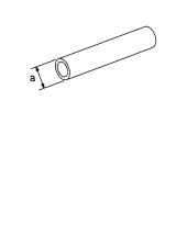
KV381054S0 |
● Removing differential side bearing outer race |
|
(J-34286) |
● Removing idler gear bearing outer race |
|
Puller |
||
a: 250 mm (9.84 in) |
||
|
||
|
b: 160 mm (6.30 in) |
|
|
NT414 |
|
|
|
|
ST33400001 |
● Installing differential side oil seal |
|
(J-26082) |
● Installing oil pump housing oil seal |
|
Drift |
||
a: 60 mm (2.36 in) dia. |
||
|
||
|
b: 47 mm (1.85 in) dia. |
|
|
NT086 |
|
|
|
|
KV40100621 |
Installing differential side oil seal (With AWD models) |
|
(J-25273) |
a: 60 mm (2.36 in) dia. |
|
Drift |
b: 47 mm (1.85 in) dia. |
|
NT086 |
|
|
ST2505S001 |
Measuring line pressure |
(J-34301) |
|
Oil pressure gauge set |
|
1.ST25051001 (J-34301)
Oil pressure gauge
2.ST25052000 (J-34301) Hose
3.ST25053000 (J-25695-3) Joint pipe
4. ST25054000 |
NT097 |
|
|
(J-25695-4) |
|
Adapter |
|
5. ST25055000 |
|
(J-25695-5) |
|
Adapter |
|
|
|
ST27180001 |
Removing idler gear |
(J-25726-A) |
a: 100 mm (3.94 in) |
Puller |
b: 110 mm (4.33 in) |
|
c: M8 x 1.25P |
|
NT424 |
Revision: 2006 July |
AT-10 |
2006 X-Trail |
|
|
|
|
PREPARATION |
|
|
|
|
|
||
|
|
|
|
||
|
Tool number |
|
|
||
|
(Kent-Moore No.) |
|
Description |
||
|
Tool name |
|
|
|
|
|
|
|
|
||
|
ST23540000 |
|
Removing and installing parking rod plate and |
||
|
(J-25689-A) |
|
manual plate retaining pins |
||
|
Pin punch |
|
|
a: 2.3 mm (0.091 in) dia. |
|
|
|
|
|
|
b: 4 mm (0.16 in) dia. |
|
|
|
|
NT442 |
|
|
|
|
|
||
|
ST25710000 |
|
Aligning groove of manual shaft and hole of |
||
|
(J-25689-A) |
|
transaxle case |
||
|
Pin punch |
|
|
a: 2 mm (0.08 in) dia. |
|
|
|
|
|
NT410 |
|
|
|
|
|
||
|
KV32101000 |
|
● Installing manual shaft retaining pin |
||
|
(J-25689-A) |
|
● Removing and installing pinion mate shaft lock pin |
||
|
Pin punch |
|
|
||
|
|
|
a: 4 mm (0.16 in) dia. |
||
|
|
|
|
|
|
|
|
|
|
NT410 |
|
|
|
|
|
||
|
KV31102400 |
|
Removing and installing clutch return springs |
||
|
(J-34285) |
|
|
a: 320 mm (12.60 in) |
|
|
Clutch spring compressor |
|
b: 174 mm (6.85 in) |
||
|
|
|
|
NT423 |
|
|
|
|
|
||
|
KV40100630 |
|
● Installing reduction pinion gear bearing inner race |
||
|
(J-26092) |
|
|
● Installing idler gear bearing inner race |
|
|
Drift |
|
|
|
|
|
|
|
|
a: 67.5 mm (2.657 in) dia. |
|
|
|
|
|
|
|
|
|
|
|
|
b: 44 mm (1.73 in) dia. |
|
|
|
|
|
c: 38.5 mm (1.516 in) dia. |
|
|
|
|
NT107 |
|
|
|
|
|
||
|
ST30720000 |
|
Installing idler gear bearing outer race |
||
|
(J-25405) |
|
|
a: 77 mm (3.03 in) dia. |
|
|
Bearing installer |
|
b: 55.5 mm (2.185 in) dia. |
||
|
|
|
|
NT115 |
|
|
|
|
|
||
|
ST35321000 |
|
Installing output shaft bearing |
||
( |
— |
) |
|
a: 49 mm (1.93 in) dia. |
|
|
Drift |
|
|
|
b: 41 mm (1.61 in) dia. |
|
|
|
|
NT073 |
|
|
|
|
|
|
|
A
B
AT
D
E
F
G
H
I
J
K
L
M
Revision: 2006 July |
AT-11 |
2006 X-Trail |

|
|
|
PREPARATION |
||
|
|
|
|||
|
|
|
|||
Tool number |
|
|
|||
(Kent-Moore No.) |
Description |
||||
Tool name |
|
|
|
||
|
|
|
|||
ST33230000 |
Installing differential side bearing inner race |
||||
(J-25805-01) |
a: 51 mm (2.01 in) dia. |
||||
Drift |
|
b: 28.5 mm (1.122 in) dia. |
|||
|
|
|
NT084 |
||
|
|
|
|||
ST33220000 |
Selecting differential side bearing adjusting shim |
||||
( |
— |
) |
a: 37 mm (1.46 in) dia. |
||
Drift |
|
b: 31 mm (1.22 in) dia. |
|||
|
|
|
c: 22 mm (0.87 in) dia. |
||
|
|
|
NT085 |
||
|
|
|
|||
ST3306S001 |
Removing differential side bearing inner race |
||||
(J-22888-D) |
a: 38 mm (1.50 in) dia. |
||||
Differential side bearing |
b: 28.5 mm (1.122 in) dia. |
||||
puller set |
|
c: 130 mm (5.12 in) |
|||
1. ST33051001 |
d: 135 mm (5.31 in) |
||||
e: 100 mm (3.94 in) |
|||||
|
(J-22888-D) |
||||
|
|
|
|||
|
Puller |
|
|
|
|
2. ST33061000 |
|
|
|||
|
(J-8107-2) |
AMT153 |
|||
|
|
|
|||
|
Adapter |
|
|
|
|
|
|
|
|||
ST3127S000 |
● Checking final drive assembly turning torque |
||||
(J-25765-A) |
● Checking reduction pinion gear turning torque |
||||
Preload gauge |
|||||
|
|
||||
1.GG91030000 (J-25765-A) Torque wrench
2.HT62940000 ( — )
Socket adapter
|
|
NT124 |
3. HT62900000 |
||
( |
— |
) |
Socket adapter |
||
|
|
|
ST35271000 |
Installing idler gear |
|
(J-26091) |
a: 72 mm (2.83 in) dia. |
|
Drift |
|
b: 63 mm (2.48 in) dia. |
NT115
Revision: 2006 July |
AT-12 |
2006 X-Trail |

|
|
PREPARATION |
|
|
|
|
|
|
|
Tool number |
|
|
(Kent-Moore No.) |
Description |
|
Tool name |
|
|
|
|
|
KV38107700 |
Selecting differential side bearing adjusting shim |
|
(J-39713) |
|
|
Preload adapter |
|
|
NT087 |
|
|
|
|
KV38105210 |
● Selecting differential side bearing adjusting shim |
|
(J-39883) |
● Checking fluid drive assembly turning torque |
|
Preload adapter |
||
|
NT075
A
B
AT
D
E
F
G
H
I
J
K
L
M
Revision: 2006 July |
AT-13 |
2006 X-Trail |

|
PREPARATION |
|
|
|
|
Commercial Service Tools |
|
ACS007QR |
|
|
|
Tool name |
|
Description |
|
|
|
Power tool |
|
Loosening bolts and nuts |
|
PBIC0190E |
|
|
|
|
Puller |
|
Removing idler gear bearing inner race |
|
NT077 |
|
|
|
|
Puller |
|
Removing reduction pinion gear bearing inner |
|
|
race |
|
|
a: 60 mm (2.36 in) dia. |
|
|
b: 35 mm (1.38 in) dia. |
|
NT411 |
|
|
|
|
Drift |
|
Installing radial needle bearing on bearing |
|
|
retainer |
|
|
a: 36 mm (1.42 in) dia. |
|
NT083 |
|
|
|
|
Drift |
|
Installing manual shaft oil seal |
|
|
a: 22 mm (0.87 in) dia. |
|
NT083 |
|
|
|
|
Drift |
|
Removing radial needle bearing from bearing |
|
|
retainer |
|
|
a: 33.5 mm (1.319 in) dia. |
|
NT083 |
|
|
|
|
Revision: 2006 July |
AT-14 |
2006 X-Trail |
|
PREPARATION |
|
|
|
|
|
|
|
|
|
|
|
|
|
Tool name |
|
Description |
|
A |
|
|
|
|
|
Drift |
|
Installing differential side bearing outer race |
|
|
|
|
(RH side) |
|
|
|
|
a: 75 mm (2.95 in) dia. |
|
B |
|
|
|
|
|
|
|
|
|
|
|
NT083 |
|
|
AT |
|
|
|
|
|
|
|
|
|
|
Drift |
|
Installing differential side bearing outer race |
|
|
|
|
(LH side) |
|
D |
|
|
a: 100 mm (3.94 in) dia. |
|
|
|
|
|
|
E |
|
NT083 |
|
|
|
|
|
|
|
F |
|
|
|
|
|
|
|
|
|
G |
|
|
|
|
H |
|
|
|
|
I |
|
|
|
|
J |
|
|
|
|
K |
|
|
|
|
L |
|
|
|
|
M |
Revision: 2006 July |
AT-15 |
2006 X-Trail |

A/T FLUID
A/T FLUID
Checking A/T Fluid
1.Warm up engine.
2.Check for A/T fluid leakage.
3.Before driving, A/T fluid level can be checked at A/T fluid temperatures of 30 to 50° C (86 to 122° F) using “COLD” range on A/ T fluid level gauge.
a.Park vehicle on level surface and set parking brake.
b.Start engine and move selector lever through each gear position. Leave selector lever in “P” position.
c.Check A/T fluid level with engine idling.
d.Remove A/T fluid level gauge and note reading. If level is at low side of either range, and A/T fluid to the A/T fluid charging pipe.
CAUTION:
When wiping away the A/T fluid level gauge, always use lint-free paper, not a cloth one.
e.Re-insert A/T fluid level gauge into A/T fluid charging pipe as far as it will go.
CAUTION:
Firmly fix the A/T fluid level gauge to the A/T fluid charging pipe using a stopper attached.
f.Remove A/T fluid level gauge and note reading. If reading is at low side of range, add ATF to the A/T fluid charging pipe.
CAUTION:
Do not overfill.
PFP:KLE40
ACS007QS
SCIA3451E
SMA051D
4.Drive vehicle for approximately 5 minutes in urban areas.
5.Recheck A/T fluid level at A/T fluid temperatures of 50 to 80° C (122 to 176° F) using “HOT” range on A/T fluid level gauge.
CAUTION:
●When wiping away the A/T fluid level gauge, always use lint-free paper, not a cloth one.
●Firmly fix the A/T fluid level gauge to the A/T fluid charging pipe using a stopper attached.
6.Check A/T fluid condition.
●If ATF is very dark or smells burned, checking operation of A/ T. Flush cooling system after repair of A/T.
●If ATF contains frictional material (clutches, bands, etc.), replace radiator and flush cooler line using cleaning solvent and compressed air after repair of A/T. Refer to CO-11, "RADIATOR" , CO-14, "RADIATOR (ALUMINUM TYPE)" .
7.Install the removed A/T fluid level gauge in the A/T fluid charging pipe.
CAUTION:
SAT638A
Firmly fix the A/T fluid level gauge to the A/T fluid charging pipe using a stopper attached.
Revision: 2006 July |
AT-16 |
2006 X-Trail |
A/T FLUID
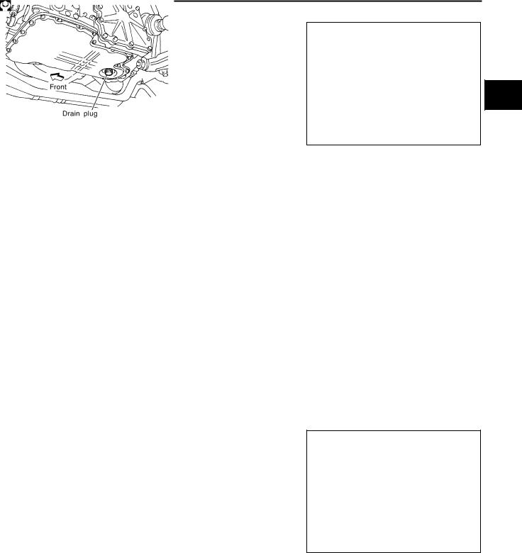
Changing A/T Fluid
1.Warm up ATF.
2.Stop engine.
3.Drain ATF from drain hole and refill with new ATF. Always refill same volume with drained fluid.
CAUTION:
Do not reuse drain plug gasket.
Fluid grade:
NISSAN Automatic Transmission Fluid (ATF),
DEXRONTM III/MERCONTM , or equivalent ATF. Refer to MA-10, "RECOMMENDED FLUIDS AND LUBRICANTS" .
Fluid capacity (With torque converter):
Approx. 8.5 (9 US qt, 7-1/2 lmp qt)
Drain plug
:34 N·m (3.5 kg-m, 25 ft-lb)
ACS007QT
SMA027D
4.Run engine at idle speed for 5 minutes.
5.Check A/T fluid level and condition. Refer to AT-16, "Checking A/T Fluid" . If ATF is still dirty, repeat steps 2 through 5.
A/T Fluid Cooler Cleaning |
ACS008HQ |
Whenever an A/T is repaired, overhauled, or replaced, the A/T fluid cooler mounted in the radiator must be inspected and cleaned.
Metal debris and friction material, if present, can become trapped in the A/T fluid cooler. This debris can contaminate the newly serviced A/T or, in severe cases, can block or restrict the flow of ATF. In either case, malfunction of the newly serviced A/T may result.
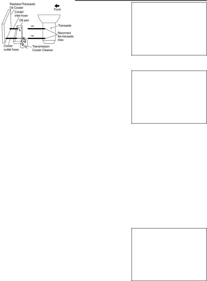
Debris, if present, may build up as ATF enters the cooler inlet. It will be necessary to back flush the cooler through the cooler outlet in order to flush out any built up debris.
A/T FLUID COOLER CLEANING PROCEDURE
1.Position an oil pan under the A/T inlet and outlet cooler hoses.
2.Identify the inlet and outlet fluid cooler hoses.
3.Disconnect the A/T fluid cooler inlet and outlet rubber hoses from the steel cooler tubes or bypass valve.
NOTE:
Replace the cooler hoses if rubber material from the hose remains on the tube fitting.
4.Allow any ATF that remains in the cooler hoses to drain into the oil pan.
SCIA5628E
A
B
AT
D
E
F
G
H
I
J
K
L
M
Revision: 2006 July |
AT-17 |
2006 X-Trail |
A/T FLUID
5.Insert the extension adapter hose of a can of Transmission Cooler Cleaner (Nissan P/N 999MP-AM006) into the cooler outlet hose.
CAUTION:
●Wear safety glasses and rubber gloves when spraying the Transmission Cooler Cleaner.
●Spray Transmission Cooler Cleaner only with adequate ventilation.
●Avoid contact with eyes and skin.
●Do not breath vapors or spray mist.
SCIA5629E
6.Hold the hose and can as high as possible and spray Transmis-
sion Cooler Cleaner in a continuous stream into the cooler outlet hose until ATF flows out of the cooler inlet hose for 5 seconds.
7.Insert the tip of an air gun into the end of the cooler outlet hose.
8.Wrap a shop rag around the air gun tip and of the cooler outlet hose.
SCIA5630E
9.Blow compressed air regulated to 5 - 9 kg/cm2 (70 - 130 psi) through the cooler outlet hose for 10 seconds to force out any remaining ATF.
10.Repeat steps 5 through 9 three additional times.
11.Position an oil pan under the banjo bolts that connect the A/T fluid cooler steel lines to the A/T.
12.Remove the banjo bolts.
13.Flush each steel line from the cooler side back toward the A/T by spraying Transmission Cooler Cleaner in a continuous stream for 5 seconds.
14.Blow compressed air regulated to 5 - 9 kg/cm2 (70 - 130 psi) through each steel line from the cooler side back toward the A/T for 10 seconds to force out any remaining ATF.
15.Ensure all debris is removed from the steel cooler lines.
16.Ensure all debris is removed from the banjo bolts and fittings.
17.Perform AT-18, "A/T FLUID COOLER DIAGNOSIS PROCEDURE" .
A/T FLUID COOLER DIAGNOSIS PROCEDURE
NOTE:
Insufficient cleaning of the cooler inlet hose exterior may lead to inaccurate debris identification.
1.Position an oil pan under the A/T inlet and outlet cooler hoses.
2.Clean the exterior and tip of the cooler inlet hose.
3.Insert the extension adapter hose of a can of Transmission Cooler Cleaner (Nissan P/N 999MP-AM006) into the cooler outlet hose.
CAUTION:
●Wear safety glasses and rubber gloves when spraying the Transmission Cooler Cleaner.
●Spray Transmission Cooler Cleaner only with adequate ventilation.
●Avoid contact with eyes and skin.
●Do not breath vapors or spray mist.
SCIA5629E
Revision: 2006 July |
AT-18 |
2006 X-Trail |

A/T FLUID
4.Hold the hose and can as high as possible and spray Transmission Cooler Cleaner in a continuous
stream into the cooler outlet hose until ATF flows out of the cooler inlet hose for 5 seconds. |
A |
||
5. Tie a common white, basket-type coffee filter to the end of the |
|
|
|
|
|
||
cooler inlet hose. |
|
||
|
|
|
B |
|
|
|
|
|
|
|
AT |
|
|
|
|
|
|
|
D |
SCIA5631E
6.Insert the tip of an air gun into the end of the cooler outlet hose.
7.Wrap a shop rag around the air gun tip and end of cooler outlet hose.
8.Blow compressed air regulated to 5 - 9 kg/cm2 (70 - 130 psi) through the cooler outlet hose to force any remaining ATF into the coffee filter.
9.Remove the coffee filter from the end of the cooler inlet hose.
10.Perform AT-19, "A/T FLUID COOLER INSPECTION PROCEDURE" .
A/T FLUID COOLER INSPECTION PROCEDURE
1.Inspect the coffee filter for debris.
a.If small metal debris less than 1mm (0.040 in) in size or metal powder is found in the coffee filter, this is normal. If normal debris is found, the A/T fluid cooler/radiator can be re-used and the procedure is ended.
SCIA5632E
SCIA2967E
b.If one or more pieces of debris are found that are over 1mm (0.040 in) in size and/or peeled clutch facing material is found in the coffee filter, the A/T fluid cooler is not serviceable. The A/T fluid cooler/radiator must be replaced and the inspection procedure is ended. Refer to CO-11, "RADIATOR" .
SCIA5659E
A/T FLUID COOLER FINAL INSPECTION
After performing all procedures, ensure that all remaining oil is cleaned from all components.
E
F
G
H
I
J
K
L
M
Revision: 2006 July |
AT-19 |
2006 X-Trail |

A/T CONTROL SYSTEM
A/T CONTROL SYSTEM
Cross-sectional View
PFP:31036
ACS007JH
SCIA4112E
1. |
Band servo piston assembly |
2. |
Reverse clutch drum |
3. |
Converter housing |
4. |
Oil pump |
5. |
Brake band |
6. |
Reverse clutch |
7. |
High clutch |
8. |
Front planetary gear |
9. |
Low one-way clutch |
10. |
Rear planetary gear |
11. |
Forward clutch |
12. |
Overrun clutch |
13. |
Low & reverse brake |
14. |
Output gear |
15. |
Idler gear |
16. |
Forward one-way clutch |
17. |
Reduction pinion gear |
18. |
Final gear |
19. |
Differential case |
20. |
Input shaft |
21. |
Torque converter |
22. |
Side cover |
23. |
Transaxle case |
|
|
Revision: 2006 July |
AT-20 |
2006 X-Trail |
A/T CONTROL SYSTEM
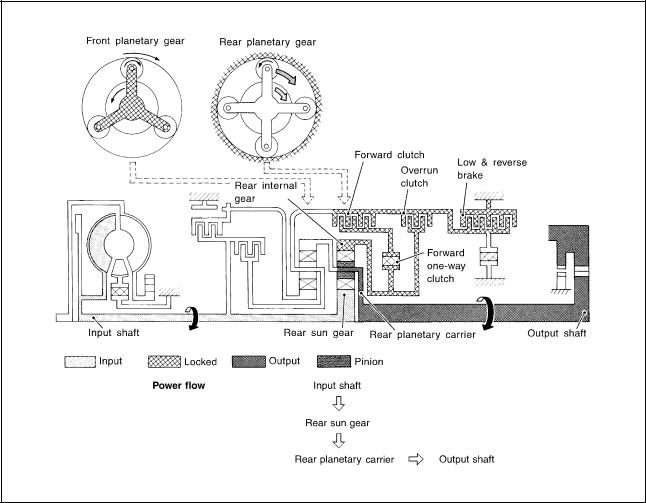
Shift Mechanism |
ACS007JI |
CONSTRUCTION
SAT998I
1. |
Torque converter |
2. |
Oil pump |
3. |
Input shaft |
4. |
Brake band |
5. |
Reverse clutch |
6. |
High clutch |
7. |
Front sun gear |
8. |
Front pinion gear |
9. |
Front internal gear |
10. |
Front planetary carrier |
11. |
Rear sun gear |
12. |
Rear pinion gear |
13. |
Rear internal gear |
14. |
Rear planetary carrier |
15. |
Forward clutch |
16. |
Forward one-way clutch |
17. |
Overrun clutch |
18. |
Low one-way clutch |
19. |
Low & reverse brake |
20. |
Parking pawl |
21. |
Parking gear |
22. |
Output shaft |
23. |
Idler gear |
24. |
Output gear |
FUNCTION OF CLUTCH AND BRAKE
|
Clutch and brake components |
Abbr. |
Function |
|
|
|
|
|
|
5 |
Reverse clutch |
R/C |
To transmit input power to front sun gear 7 . |
|
|
|
|
|
|
6 |
High clutch |
H/C |
To transmit input power to front planetary carrier 10 . |
|
|
|
|
|
|
15 |
Forward clutch |
F/C |
To connect front planetary carrier 10 with forward one-way clutch 16 . |
|
|
|
|
|
|
17 |
Overrun clutch |
O/C |
To connect front planetary carrier 10 with rear internal gear 13 . |
|
|
|
|
|
|
4 |
Brake band |
B/B |
To lock front sun gear 7 . |
|
|
|
|
|
|
16 |
Forward one-way clutch |
F/O.C |
When forward clutch 15 is engaged, to stop rear internal gear 13 from rotating |
|
in opposite direction against engine revolution. |
||||
|
|
|
||
|
|
|
|
|
18 |
Low one-way clutch |
L/O.C |
To stop front planetary carrier 10 from rotating in opposite direction against |
|
engine revolution. |
||||
|
|
|
||
|
|
|
|
|
19 |
Low & reverse brake |
L & R/B |
To lock front planetary carrier 10 . |
|
|
|
|
|
A
B
AT
D
E
F
G
H
I
J
K
L
M
Revision: 2006 July |
AT-21 |
2006 X-Trail |

A/T CONTROL SYSTEM
CLUTCH AND BAND CHART
|
|
|
|
|
|
|
|
Band servo |
|
|
|
|
|
|
|
|
||
Shift posi- |
R/C |
H/C |
F/C |
O/C |
|
|
|
|
|
F/O.C |
L/O.C |
L&R/B |
Lock- |
|
|
|
||
2nd |
|
3rd |
|
4th |
Remarks |
|||||||||||||
tion |
|
5 |
6 |
15 |
17 |
|
|
16 |
18 |
19 |
up |
|||||||
|
|
releas |
|
|||||||||||||||
|
|
|
|
|
|
|||||||||||||
|
apply |
|
|
apply |
|
|
|
|||||||||||
|
|
|
|
|
|
|
|
e |
|
|
|
|
|
|
|
|
||
|
|
|
|
|
|
|
|
|
|
|
|
|
|
|
|
|
|
|
|
|
|
|
|
|
|
|
|
|
|
|
|
|
|
|
|
|
|
P |
|
|
|
|
|
|
|
|
|
|
|
|
|
|
PARK |
|
||
|
|
|
|
|
|
|
|
|
|
|
|
|
|
POSITION |
||||
|
|
|
|
|
|
|
|
|
|
|
|
|
|
|
|
|||
|
|
|
|
|
|
|
|
|
|
|
|
|
|
|
|
|
||
R |
|
|
|
|
|
|
|
|
|
|
|
|
|
|
REVERSE |
|||
|
|
|
|
|
|
|
|
|
|
|
|
|
|
POSITION |
||||
|
|
|
|
|
|
|
|
|
|
|
|
|
|
|
|
|||
|
|
|
|
|
|
|
|
|
|
|
|
|
|
|
|
|
||
N |
|
|
|
|
|
|
|
|
|
|
|
|
|
|
NEUTRAL |
|||
|
|
|
|
|
|
|
|
|
|
|
|
|
|
POSITION |
||||
|
|
|
|
|
|
|
|
|
|
|
|
|
|
|
|
|||
|
|
|
|
|
|
|
|
|
|
|
|
|
|
|
|
|
||
|
|
|
|
|
|
|
|
|
|
|
|
|
|
|
|
Automatic |
||
D*4 |
|
1st |
|
|
|
*1D |
|
|
|
|
|
B |
B |
|
|
shift |
|
|
|
|
|
|
|
|
|
|
|
|
|
1 |
2 |
3 |
|||||
|
|
|
|
|
|
|
|
|
|
|
|
|
|
|
|
|||
|
|
|
|
|
|
|
|
|
|
|
|
|
|
|
|
|
4 |
|
|
|
|
|
|
|
|
|
|
|
|
|
|
|
|
|
|
|
|
|
|
2nd |
|
|
|
*1A |
|
|
|
|
|
B |
|
|
|
|
|
|
|
|
|
|
|
|
|
|
|
|
|
|
|
|
|
|
|
|
|
|
|
3rd |
|
|
|
*1A |
*2C |
|
C |
|
|
B |
|
|
*1 |
|
|
|
|
|
|
|
|
|
|
|
|
|
|
|
|
|
|
|
|
|
|
|
|
4th |
|
|
C |
|
*3C |
|
C |
|
|
|
|
|
|
|
|
|
|
|
|
|
|
|
|
|
|
|
|
|
|
|
|
|
|
|
|
|
|
1st |
|
|
|
|
|
|
|
|
|
B |
B |
|
|
Automatic |
||
2 |
|
|
|
|
|
|
|
|
|
|
|
|
|
|
|
|||
|
|
|
|
|
|
|
|
|
|
|
|
|
|
|
||||
|
2nd |
|
|
|
|
|
|
|
|
|
B |
|
|
|
shift |
|
||
|
|
|
|
|
|
|
|
|
|
|
|
|
|
|
|
1 |
2 |
3 |
|
|
3rd |
|
|
|
|
*2C |
|
C |
|
|
B |
|
|
|
|||
|
|
|
|
|
|
|
|
|
|
|
|
|
|
|
||||
|
|
|
|
|
|
|
|
|
|
|
|
|
|
|
|
|
|
|
|
|
1st |
|
|
|
|
|
|
|
|
|
B |
B |
|
|
Locks (held |
||
|
|
|
|
|
|
|
|
|
|
|
|
|
|
|
|
|||
1 |
|
|
|
|
|
|
|
|
|
|
|
|
|
|
|
stationary) |
||
|
2nd |
|
|
|
|
|
|
|
|
|
B |
|
|
|
||||
|
|
|
|
|
|
|
|
|
|
|
|
|
in 1st speed |
|||||
|
|
|
|
|
|
|
|
|
|
|
|
|
|
|
|
|||
|
|
3rd |
|
|
|
|
*2C |
|
C |
|
|
B |
|
|
|
1 |
2 |
3 |
|
|
|
|
|
|
|
|
|
|
|
|
|
|
|
||||
|
|
|
|
|
|
|
|
|
|
|
|
|
|
|
|
|
|
|
●*1: Operates when OD OFF. (OD OFF indicator lamp is on.)
●*2: Oil pressure is applied to both 2nd “apply” side and 3rd “release” side of band servo piston. However, brake band does notcontract because oil pressure area on the “release” side is greater than that on the “apply” side.
●*3: Oil pressure is applied to 4th “apply” side in condition *2 above, and brake band contracts.
●*4: A/T will not shift to 4th when OD OFF. (OD OFF indicator lamp is on.)
● : Operates.
●A: Operates when throttle opening is less than 3/16, activating engine brake.
●B: Operates during “progressive” acceleration.
●C: Operates but does not affect power transmission.
●D: Operates when throttle opening is less than 3/16, but does not affect engine brake.
Revision: 2006 July |
AT-22 |
2006 X-Trail |

A/T CONTROL SYSTEM
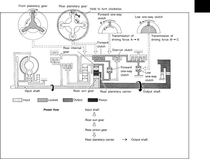
POWER TRANSMISSION |
|
“N” and “P” Positions |
A |
●“N” position
Power from the input shaft is not transmitted to the output shaft because the clutches do not operate.
● “P” position |
B |
|
|
||
Similar to the “N” position, the clutches do not operate. The parking pawl engages with the parking gear to |
|
|
mechanically hold the output shaft so that the power train is locked. |
|
|
|
|
|
AT
D
E
F
G
H
SAT991I
I
J
K
L
M
Revision: 2006 July |
AT-23 |
2006 X-Trail |
|
A/T CONTROL SYSTEM |
|
|
|
|
“11 ” Position |
|
|
|
|
|
● Forward clutch |
As overrun clutch engages, rear internal gear is locked by the operation of low and |
|
● Forward one-way clutch |
reverse brake. |
|
This is different from that of D1 and 21 . |
||
● Overrun clutch |
||
|
||
● Low & reverse brake |
|
|
|
|
|
Engine brake |
Overrun clutch always engages, therefore engine brake can be obtained when deceler- |
|
|
ating. |
|
|
|
SCIA1816E
Revision: 2006 July |
AT-24 |
2006 X-Trail |
|
A/T CONTROL SYSTEM |
|
|
|
|
“D1 ” and “21 ” Positions |
|
|
|
|
|
● Forward one-way clutch |
Rear internal gear is locked to rotate counterclockwise because of the functioning of |
|
● Forward clutch |
these three clutches. |
|
|
||
● Low one-way clutch |
|
|
|
|
|
Overrun clutch |
D1 : OD OFF (OD OFF indicator lamp is on) and throttle opening is less than 3/16 |
|
21 : Always engaged |
||
engagement conditions |
||
At D1 and 21 positions, engine brake is not activated due to free turning of low one- |
||
(Engine brake) |
||
way clutch. |
||
|
||
|
|
SAT377J
A
B
AT
D
E
F
G
H
I
J
K
L
M
Revision: 2006 July |
AT-25 |
2006 X-Trail |

|
A/T CONTROL SYSTEM |
|
|
|
|
“D2 ”, “22 ” and “12 ” Positions |
||
|
|
|
● Forward clutch |
Rear sun gear drives rear planetary carrier and combined front internal gear. Front internal gear now |
|
● Forward one-way |
rotates around front sun gear accompanying front planetary carrier. |
|
As front planetary carrier transfers the power to rear internal gear through forward clutch and forward one- |
||
clutch |
||
way clutch, this rotation of rear internal gear increases the speed of rear planetary carrier compared with |
||
● Brake band |
||
that of the 1st speed. |
||
|
||
|
|
|
Overrun clutch |
D2 : OD OFF (OD OFF indicator lamp is on) and throttle opening is less than 3/16 |
|
engagement conditions |
22 and 12 : Always engaged |
|
|
|
|
SAT378J
Revision: 2006 July |
AT-26 |
2006 X-Trail |
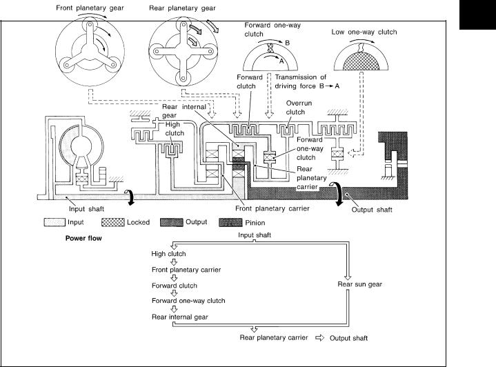
|
A/T CONTROL SYSTEM |
|
|
|
|
“D3 ”, “23 ” and “13 ” Positions |
||
|
|
|
● High clutch |
Input power is transmitted to front planetary carrier through high clutch. And front planetary carrier is con- |
|
● Forward clutch |
nected to rear internal gear by operation of forward clutch and forward one-way clutch. |
|
This rear internal gear rotation and another input (the rear sun gear) accompany rear planetary carrier to |
||
● Forward one-way |
||
turn at the same speed. |
||
clutch |
||
|
||
|
|
|
Overrun clutch |
D3 : OD OFF (OD OFF indicator lamp is on) and throttle opening is less than 3/16 |
|
engagement conditions |
23 and 13 : Always engaged |
|
|
|
|
SCIA7229E
A
B
AT
D
E
F
G
H
I
J
K
L
M
Revision: 2006 July |
AT-27 |
2006 X-Trail |
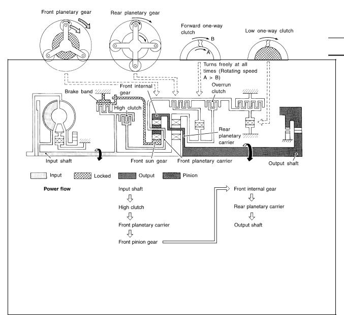
|
A/T CONTROL SYSTEM |
|
|
|
|
“D4 ” (OD) Position |
|
|
|
|
|
● High clutch |
Input power is transmitted to front carrier through high clutch. |
|
● Brake band |
This front carrier turns around the sun gear which is fixed by brake band and makes |
|
front internal gear (output) turn faster. |
||
|
●Forward clutch (Does not affect power transmission)
Engine brake
At D4 position, there is no one-way clutch in the power transaxle line and engine brake can be obtained when decelerating.
SAT380J
Revision: 2006 July |
AT-28 |
2006 X-Trail |
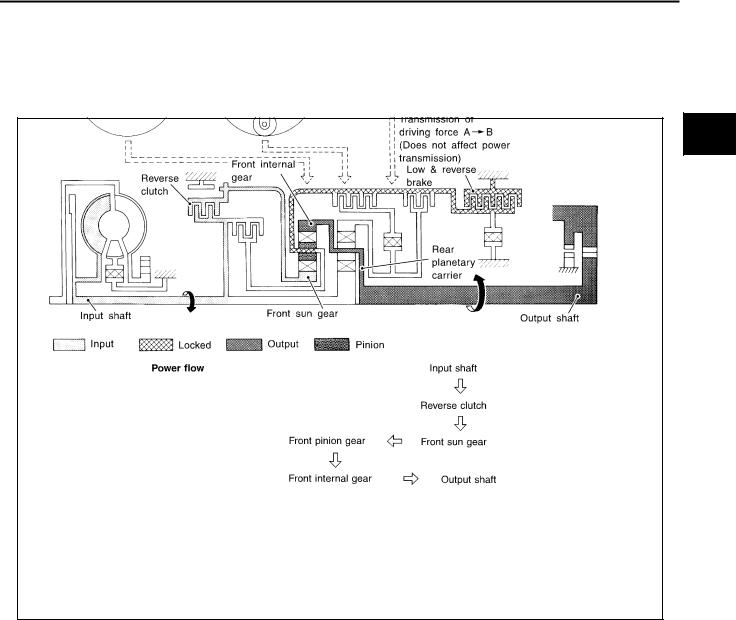
A/T CONTROL SYSTEM
“R” Position
● Reverse clutch |
Front planetary carrier is stationary because of the operation of low and reverse brake. |
|
● Low & reverse brake |
Input power is transmitted to front sun gear through reverse clutch, which drives front |
|
internal gear in the opposite direction. |
||
|
||
|
|
|
Engine brake |
As there is no one-way clutch in the power transaxle line, engine brake can be |
|
obtained when decelerating. |
||
|
||
|
|
SAT381J
A
B
AT
D
E
F
G
H
I
J
K
L
M
Revision: 2006 July |
AT-29 |
2006 X-Trail |

A/T CONTROL SYSTEM
TCM Function |
ACS007JJ |
The function of the TCM is to:
●Receive input signals sent from various switches and sensors.
●Determine required line pressure, shifting point, lock-up operation, and engine brake operation.
●Send required output signals to the respective solenoids.
CONTROL SYSTEM OUTLINE
The automatic transmission senses vehicle operating conditions through various sensors or signals. It always controls the optimum shift position and reduces shifting and lock-up shocks.
SWITCHES & SENSORS |
|
TCM |
|
ACTUATORS |
|
|
|
|
|
PNP switch |
|
Shift control |
|
|
Accelerator pedal position signal |
|
Line pressure control |
|
Shift solenoid valve A |
Closed throttle position signal |
|
Lock-up control |
|
|
|
|
Shift solenoid valve B |
||
Wide open throttle position signal |
|
Overrun clutch control |
|
|
|
|
Overrun clutch solenoid valve |
||
Engine speed signal |
|
Timing control |
|
|
|
|
Torque converter clutch solenoid |
||
A/T fluid temperature sensor |
|
Fail-safe control |
|
|
|
|
valve |
||
Revolution sensor |
|
Self-diagnosis |
|
|
|
|
Line pressure solenoid valve |
||
Vehicle speed sensor |
|
CONSULT-II communication line |
|
|
|
|
OD OFF indicator lamp |
||
Overdrive control switch signal |
|
control |
|
|
|
|
|
||
Stop lamp switch signal |
|
Duet-EU control |
|
|
|
|
|
|
|
CONTROL SYSTEM DIAGRAM
SCIA7349E
Revision: 2006 July |
AT-30 |
2006 X-Trail |
Loading...