


XTrail T30 2006
Table of contents
 Loading...
AUDIO, VISUAL & TELEP HO N E SYSTEM
K ELECTRICAL
A
B
SECTION AV
AUDIO, VISUAL & TELEPHONE SY STEM
CONTENTS
PRECAUTIONS .......................................................... 3
Precautions for Supplemental Rest raint System
(SRS) “AIR BAG” and “SEAT BELT PRE-TEN-
SIONER” .................................................................. 3
PREPARATION ........................................................... 4
Commercial Service Tools ........................................ 4
AUDIO ......................... .......................... ...................... 5
System Description .................................................. 5
Component Parts Location ....................................... 6
Wiring Diagram —AUDIO— ..................................... 7
WITHOUT NAVI .... ...... ....... ...... ....... ...... ................ 7
WITH NAVI ............................................................ 9
Terminals and Reference Value for Audio Unit ........11
Trouble Diagnoses ................................................. 12
AUDIO UNIT ....................................................... 12
Inspection ................. .............................................. 12
AUDIO UNIT ....................................................... 12
ANTENNA .......................... ................................. 12
Removal and Installation of Audio Unit (Without
NAVI) ...................................................................... 13
REMOVAL ........................................................... 13
INSTALLATION ................................................... 13
Removal and Installation of Audio Unit (With NAVI) ... 13
REMOVAL ........................................................... 13
INSTALLATION ................................................... 13
Removal and Installation of Speaker ..................... 13
REMOVAL ........................................................... 13
INSTALLATION ................................................... 13
Removal and Installation of Tweeter ...................... 14
REMOVAL ........................................................... 14
INSTALLATION ................................................... 14
AUDIO ANTENNA ......................... ....... ...... ....... ....... 15
Antenna Route ....................................................... 15
Removal and Installation of Roof Antenna ............. 15
NAVIGATION SYSTEM ............................................ 16
System Description ................................................ 16
NAVIGATION SYSTEM ....................................... 16
Component Description .......................................... 19
NAVI CONTROL UNIT ........................................ 19
GPS ANTENNA .................................................. 19
DISPLAY .............................................................. 20
NAVI SWITCH .....................................................20
TRANSFER UNIT ................................................20
VOICE CHANGE RELAY ....................................20
Precautions for NAVI Control Unit Replacement ....21
Component Parts And Harness Connector Location
...21
Schematic .................... ....................................... ....22
Wiring Diagram — NAVI — ....................................23
Terminals and Reference Value for NAVI Control
Unit .........................................................................27
Terminals and Reference Value for Display ............29
Terminals and Reference Value for NAVI Switch .... 31
Terminals and Reference Value for Transfer Unit ... 31
Terminals and Reference Value for V oice Change
Relay ......................................................................32
Self-Diagnosis Function ..........................................34
DESCRIPTION ............................ ........................34
DIAGNOSIS ITEM ...............................................34
Self-Diagnosis Mode .............................................. 35
OPERATION PROCEDURE ................................ 35
SELF–DIAGNOSIS RESULT ............................... 36
CONFIRMATION/ADJUSTMENT Mode ................. 37
OPERATION PROCEDURE ................................ 37
DISPLAY .............................................................. 38
VEHICLE SIGNALS .................... ....... ...... ....... .... 39
HISTORY OF ERRORS ......................................39
NAVIGATION ....................................................... 42
Communication Line Check (Between NAVI Control
Unit and Transfer Unit) ........................................... 43
Vehicle Speed Signal Check .................................. 44
Illumination Signal Check ....................................... 45
Ignition Signal Check ..............................................45
Reverse Signal Check ............................................ 46
RGB Image Is Not Displayed ..................................46
RGB Screen Is Rolling ............................................47
Color of RGB Image Is Not Proper ......................... 48
Guide Sound Is Not Heard .....................................50
NAVI Switch Cannot Be Operated ......... ...... ....... ....52
Example of Symptoms Judged Not Malfunction .....54
C
D
E
F
G
H
I
J
AV
L
M
Revision: 2006 July 2006 X-Trail
AV-1

BASIC OPERATIONS .........................................54
VEHICLE MARKS ...............................................54
MAP DVD-ROM ...................................................55
DESTINATION, W AY POINTS OR MENU CON-
TENTS CANNOT BE CHOSEN OR SET ............55
VOICE GUIDANCE .............................................55
ROUTE CALCULATION ......................................56
EXAMPLES OF VEHICLE MARK DISPLACE-
MENT ..................................................................57
VEHICLE MARK SHOWS A POSITION WHICH
IS COMPLETELY WRONG ................................. 60
VEHICLE MARK JUMPS .....................................60
VEHICLE MARK IS IN A RIVER OR SEA ...........61
VEHICLE MARK AUTOMATICALLY ROTATES ...61
WHEN DRIVING ON SAME ROAD, SOMETIMES VEHICLE MARK IS IN RIGHT PLACE
AND SOMETIMES IT IS WRONG PLACE ..........61
LOCATION CORRECTION BY MAP-MATCH-
ING IS SLOW ......................................................61
ALTHOUGH GPS RECEIVING DISPLAY IS
GREEN, VEHICLE MARK DOES NOT RETURN
TO CORRECT LOCATION ..................................61
NAME OF CURRENT PLACE IS NOT DIS-
PLAYED ....................... .......................... ..............61
CONTENTS OF DISPLAY DIFFER FOR BIRD-
VIEW® AND THE (FLAT) MAP SCREEN ............61
Program Loading ....................................................62
Removal and Installation of NAVI Control Unit ........63
REMOVAL ........................................................ ....63
INSTALLATION ................................................ ....63
Removal and Installation of GPS Antenna ..............63
REMOVAL ........................................................ ....63
INSTALLATION ................................................ ....63
Removal and Installation of GPS Antenna Feeder ...64
REMOVAL ........................................................ ....64
INSTALLATION ................................................ ....64
Removal and Installation of NAVI Switch ................65
REMOVAL ........................................................ ....65
INSTALLATION ................................................ ....65
Removal and Installation of Display ........................65
REMOVAL ........................................................ ....65
INSTALLATION ................................................ ....65
Removal and Installation of Transfer Unit ...............66
REMOVAL ........................................................ ....66
INSTALLATION ................................................ ....66
Removal and Installation of Voice Change Relay ...66
REMOVAL ........................................................ ....66
INSTALLATION ................................................ ....66
Revision: 2006 July 2006 X-Trail
AV-2

PRECAUTIONS
PRECAUTIONS PFP:00011
Precautions for Supplemental Restraint System (SRS) “AIR BAG” and “SEAT BELT PRE-TENSIONER”
AKS00BEC
A
The Supplemental Rest raint System such as “AIR BAG” and “SEAT BELT PRE-TENSIONER”, used al ong
with a front seat belt, helps to redu ce th e risk or se verit y of i njury to the driv er and front passenge r for ce rtain
types of col lision. Information necessary to service the system safely is includ ed in the SRS a nd SB section of
this Service Manual.
WARNING:
● To avoid rendering the SRS inopera tive, whi ch could incr ease the risk of pe rsonal injury or death
in the event of a collision which would result in air bag inflation, all maintenance must be performed by an authorized NISSAN/INFINITI dealer.
● Improper maintenance, inc luding incorrect removal and installation of the SRS, can lead to per-
sonal injury ca use d by unintentional activ atio n of the system. For re mo va l of Spiral Cable and Air
Bag Module, see the SRS sec tion.
● Do not use electrical test equ ipment o n any circu it related to the SRS unless in structed to in this
Service Manual. SRS wiring harnesses can be identified by yellow and/or orange harnesses or
harness connectors.
B
C
D
E
F
G
H
I
AV
J
L
M
Revision: 2006 July 2006 X-Trail
AV-3

PREPARATION
PREPARATION PFP:00002 Commercial Service Tools AKS00BVB
Tool name Description
Loosening bolts and nuts
Power tool
PBIC0191E
Revision: 2006 July 2006 X-Trail
AV-4

AUDIO
AUDIO PFP:28111
System Description AKS00F9B
Refer to Owner's Manual for audio system operating instructions.
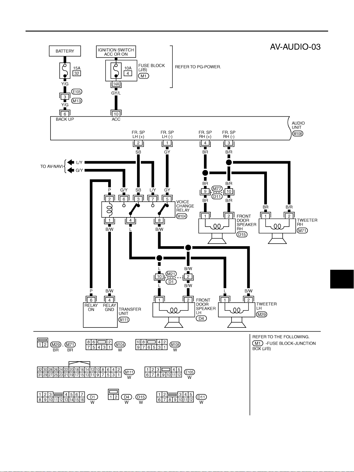
Power is supplied at all times
● through 15A fuse [No. 32, located in the fuse and fusible link box]
● to audio unit terminal 6.
With the ignition switch in the ACC or ON position, power is supplied
● through 10A fuse [No. 4, located in the fuse block (J/B)]
● to audio unit terminal 10.
Ground is supplied through the case of the audio unit.
When audio switch is pushed, au dio signals are su pplied
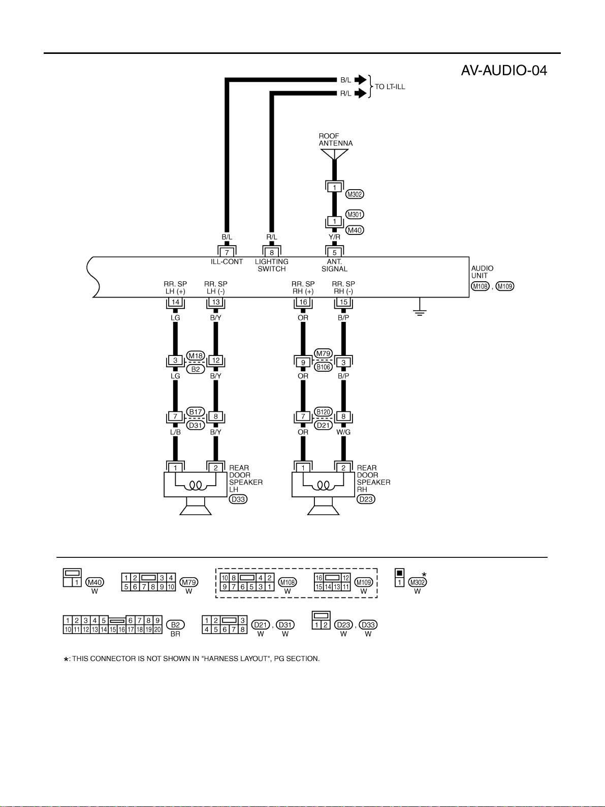
● through audi o unit terminal s 1, 2, 3, 4, 13, 14, 15, and 16
● to terminals 1 and 2 of front door speaker LH and RH
● to terminals 1 and 2 of rear spea ker LH and RH
● to terminals 1 and 2 of tweeter LH and RH.
A
B
C
D
E
F
G
AV
H
I
J
L
M
Revision: 2006 July 2006 X-Trail
AV-5
AUDIO
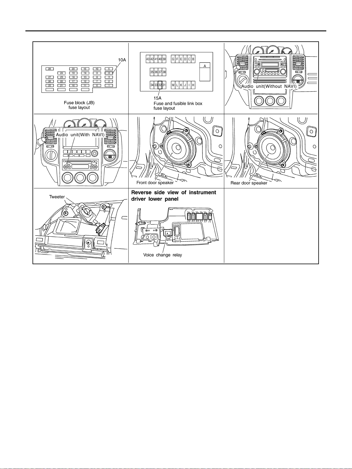
Component Parts Location AKS00F9C
SKIB6771E
Revision: 2006 July 2006 X-Trail
AV-6

AUDIO
Wiring Diagram —AUDIO— AKS00F9D
WITHOUT NAVI
A
B
C
D
E
F
G
AV
H
I
J
L
M
TKWB2266E
Revision: 2006 July 2006 X-Trail
AV-7

AUDIO
TKWB0201E
Revision: 2006 July 2006 X-Trail
AV-8
WITH NAVI
AUDIO
A
B
C
D
E
F
G
AV
H
I
J
L
M
TKWB2267E
Revision: 2006 July 2006 X-Trail
AV-9
AUDIO
TKWB2268E
Revision: 2006 July 2006 X-Trail
AV-10

AUDIO
Terminals and Reference Value for Audio Unit AKS00F9G
Terminal
(Wire color)
(+) (–)
Item
Signal
input/
output
Ignition
switch
Condition
Reference value
Operation
A
B
2
*1
(L)
(SB)
(BR) 3(B/R)
(Y/R)
(Y/G)
(B/L)
(R/L)
(GY/L)
(B/W)
*2
(GY)
4
5
Ground Antenna signal Output ON — Approx. 12 V
6
Ground Battery power supply Input OFF — Battery voltage
7
Ground Illmination control signal Input OFF
8
Ground Lighting switch signal Input OFF
10
Ground ACC power supply Input ACC — Battery voltage
1
*1
Audio signal front LH Output ON Receive audio signal
*2
Audio signal front RH Output ON Receive audio signal
Illmination control switch is
operated by lighting switch in
ON posit ion
Lighting switch position
1st or 2nd.
Lighting switch position OFF Approx. 0 V
C
D
SKIB3609E
E
F
SKIB3609E
G
H
Changes between approx. 0 V
and approx. 12 V
I
Approx.12 V
J
14
(LG)13(B/Y)
16
(OR)15(B/P)
*1: Without NAVI
*2: With NAVI
Audio signal rear LH Output ON Receive audio signal
Audio signal rear RH Output ON Receive audio signal
AV
L
SKIB3609E
M
SKIB3609E
Revision: 2006 July 2006 X-Trail
AV-11

AUDIO
Trouble Diagnoses AKS00F9J
AUDIO UNIT
Symptom Possible causes Repair order
Audio unit inoperative (no digital
display and no sound from speakers).
Individual rear speaker is noisy or
inoperative.
AM/FM stations are weak or noisy. 1. Roof ant enna
Audio unit generates noise in AM
and FM modes with engine running.
Audio unit generates noise in AM
and FM modes with accessories
on (switch pops and motor noise).
1.10A fuse
2.15A fuse
3.Audio unit ground
4.Audio unit
1.Each speaker
2.Output circuit to each speaker
2.Audio unit ground
3.Audio unit
1.Poor audio unit ground
2.Loose or missing ground bonding straps
3.Ignition condenser or rear window defogg er
noise suppressor condenser
4.Ignition coil
5.Audio unit
1.Poor audio unit ground
2.Antenna
3.Accessory ground
4.Malfunctioning accessory
1.Check 10A fuse [No. 4, located in fuse block
(J/B)]. Turn ignition switch ON and verify that
battery positive voltage is present at terminal
10 of audio unit.
2.Check 15A fuse (No. 32, located in fuse and
fusible link box) and verify that battery positive voltage is present at terminal 6 of audio
unit.
3.Check audio unit ground.
4.Remove audio unit for repair.
1.Check speaker.
2.Check the output circuits to each speaker
between audio unit and each speaker.
1.Check roof antenna.
2.Check audio unit ground condition.
3.Remove audio unit for repair.
1.Check audio unit ground.
2.Check ground bonding straps.
3.Replace ignition condenser or rear window
defogger noise suppressor condenser.
4.Check ignition coil.
5.Remove audio unit for repair.
1.Check audio unit ground.
2.Check antenna.
3.Check accessory ground.
4.Replace accessory.
Inspection AKS00F9K
AUDIO UNIT
All voltage inspections are made with:
● Ignition switch ON or ACC
● Audio unit ON
● Audio unit connected
ANTENNA
Using a jumper wire, clip an auxiliary ground between antenna and body.
● If reception improves, check antenna grou nd (at body surface).
● If recepti on does not improv e, check main feed er cable for short circuit or open ci rcuit.
Revision: 2006 July 2006 X-Trail
AV-12

AUDIO
Removal and Installation of Audio Unit (Without NAVI) AKS00F9O
REMOVAL
1. Remove instrument cluster lid C. Refer to IP-11, "Removal and Installation" .
2. Remove screw s and connectors, and remove audio unit.
A
B
C
D
SKIA9194E
3. Remove screw s and brackets.
INSTALLATION
Installation is the reverse order of removal.
Removal and Installation of Audio Unit (With NAVI) AKS00F9P
REMOVAL
1. Remove instrument cluster lid C. Refer to IP-11, "Removal and Installation" .
2. Remove screw s and connectors, remove audio unit.
SKIB6772E
3. Remove screw s, and brackets.
INSTALLATION
Installation is the reverse order of removal.
E
F
G
H
I
J
AV
L
Removal and Installation of Speaker AKS00F9Q
REMOVAL
1. Remove door finisher. Refer to EI-32, "Removal and Installation" .
2. Remove screws and remove speaker.
SKIA0001E
INSTALLATION
Installation is the reverse order of removal.
Revision: 2006 July 2006 X-Trail
AV-13
M
AUDIO
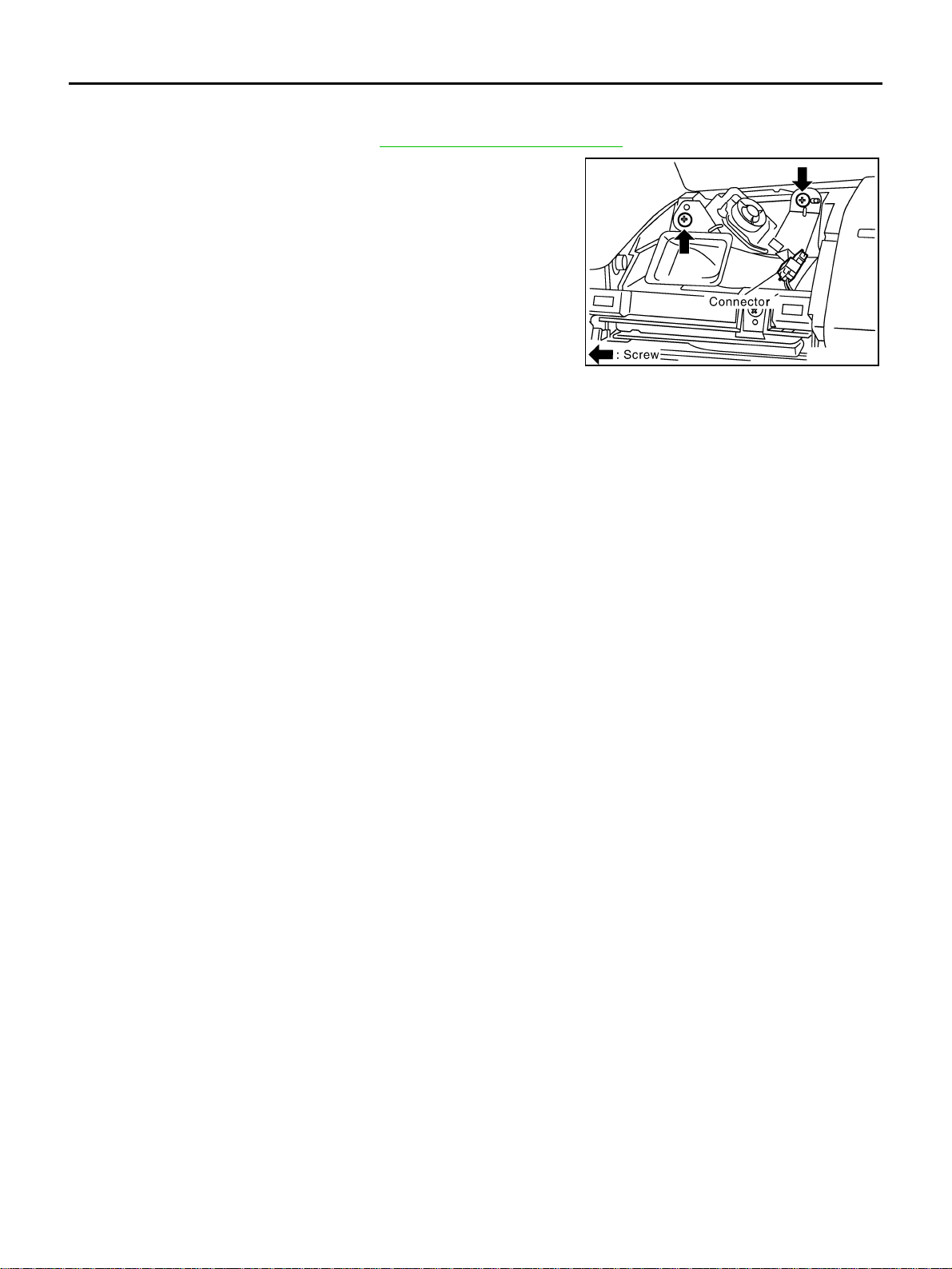
Removal and Installation of Tweeter AKS00F9R
REMOVAL
1. Remove front speaker grille. Refer to IP-11, "Removal and Installation" .
2. Remove screws and remove tweeter.
SKIA0002E
INSTALLATION
Installat ion is the rever se order of removal.
Revision: 2006 July 2006 X-Trail
AV-14

AUDIO ANTENNA
AUDIO ANTENNA PFP:28200
Antenna Route AKS00F9S
A
B
C
D
E
F
G
SKIB6773E
Removal and Installation of Roof Antenna AKS00F9T
1. Remove headlining.
● Refer to EI-40, "Removal an d Ins tal la tio n" in “Exteri or/I nte rio r
(EI)” section.
2. Remove roof antenna mounting nut, antenna plug, and power
connector. Then remove roof antenna.
SKIA9663E
H
I
J
AV
L
M
SKIA0009E
Revision: 2006 July 2006 X-Trail
AV-15

NAVIGATION SYSTEM
NAVIGATION SYSTEM PFP:25915 System Description AKS00F7M
NAVIGATION SYSTEM
For details of navigation system operation procedure, refer to navigation system owner's manual.
Location Detection Principle
The navigation system periodically calculates the vehicle's current
position accor ding to the following three s ignals:
● Travel distance of the vehicle as determined by the vehicle
speed sensor
● Turning angle of the vehicle as determined by the gyroscope
(angular vel ocity sensor)
● Direction of vehicle travel as determined by the GPS antenna
(GPS information)
The current position of the vehicle is then identified by comparing the
calculated vehicle position with map data read from the map DVDROM, which is stored in the DVD-ROM drive (map-matching), and
indicated on the screen as a vehicle mark. More accurate data is judged and used by comparing vehicle position detection results found by the GPS with the result by map-matching.
The current ve hicle position will b e calculated by de tecting the distance the vehicle moved from the previous calculation point and its
direction.
● Travel distanc e
Travel distance calculations are based on the vehicle speed
sensor input signal. Therefore, the calculation may become
incorrect as the tires w ear down. To preven t this, an automatic
distance correction function has been adopted.
● Travel direction
Change in the trav el direction of the vehicle is ca lculated by a
gyroscope (angular velocity sensor) and a GPS antenna (GPS
information). They have both advantages and disadvantages.
SKIB1058E
SEL684V
Type Advantage Disadvantage
Gyroscope
(angular velocity sensor)
GPS antenna
(GPS information)
Can detect the vehicle's turning angle qui te
accurately.
Can detect the vehicle's travel direction
(North/South/East/West).
Direction errors may accumulate when vehicle is
driven for long distances without stopping.
Correct direction cannot be detected when vehicle speed is low.
More accurate traveling direction is detected because priorities are set for the signals from these two
devices according to the situation.
Revision: 2006 July 2006 X-Trail
AV-16

NAVIGATION SYSTEM
Map-Matching
Map-matching compares a current lo cation detecte d by the method
in the “Locati on D etecti on P rinci ple“ (re fer t o AV-16
data from Map DVD-ROM stored in DVD-ROM drive.
NOTE:
The road map data is based on data stored in the map DVD-ROM.
) with a road map
A
B
C
SEL685V
The vehicle position may not be corrected under the following circumstances and after driving for a certain
time when GPS infor mation is difficult to rece ive. In this case , the vehicle mark on th e display must be corrected manually.
● In map-matching, alternative routes to reach the destination will
be shown and prio ritized, after the road on which the vehicl e is
currently driven has been judged and the vehicle mark has been
repositioned.
If there is an error in distance and/or direction, alternative routes
will be shown in differen t orde r of priorit y, and the incorrect road
can be avoided.
If two roads are ru nn ing in paral lel , th ey are of th e s am e p rio rity.
Therefore, the vehi cle ma rk may appear on either of th em alternately, depending on maneuvering of the steering wheel and
configuration of the road.
● Map-matching does not function correctly when a road on which
SEL686V
the vehicle is driving is new and not recorded in the map DVDROM, or when road pattern stored in the map data and the
actual road pattern are different due to repair.
When driving on a road not present in the map, the map-matching function may find anothe r road and position the vehic le mark
on it. Then, when the correct road is detected, the vehicle mark
may change to it.
● Effective range for comparing the vehicle position and travel
direction calcul ated by the distance and direc tion with the road
data read from the map DVD-ROM is limited. Therefore, when
SKIA0613E
there is an excessive gap between current vehicle position and
the position on the map, correction by map-matching is not possible.
D
E
F
G
H
I
J
AV
L
M
Revision: 2006 July 2006 X-Trail
AV-17

NAVIGATION SYSTEM
GPS (Global Positioning System)
GPS (Global Positioning System) was developed for and is controlled by the US Department of Defense. The system utilizes GPS
satellites (NAVSTAR), sending out radio waves while flying on an
orbit around the earth at an altitude of approximately 21,000 km.
The GPS receiver c alculates the vehicle's positi on in three dimensions (latitude/longitude/altitude) according to the time lag of the
radio waves received from four or more GPS satellites (three-dimensional positioning). If radio waves were received only from three
GPS satellites , the GPS r eceiver ca lculates the vehicle's position i n
two dimensions (latitude/longitude), u tilizing the altitude data ca lculated previously with radio waves from four or more GPS satellites
(two-dimensional positioning).
Position correction by GPS is not available while the vehicle is stopped.
Accuracy of GPS will deteriorate under the following conditions:
● In two-dimensional positioning, GPS accuracy will deteriorate when altitude of the vehicle position
changes.
● The accura cy can be eve n lo w er de pe nd ing on th e ar ra ng em en t of th e GP S sat el l ites ut il i zed for the pos i-
tioning.
● Position detection is not possible when vehicle is in an area where radio waves from the GPS satellite do
not reach, such as in a tunnel, parking lot in a building, and under an elevated highway. Radio waves from
the GPS satellites may not be received when some object is located over the GPS antenna.
NOTE:
● Even a high-precision three dimensional positioning, t he detection re sult has an error about 10 m (30 ft).
● Because the signals of GPS satellite is controlled by the Tracking and Control Center in the United States,
the accuracy may be degraded lower intentionally or the radio waves may stop.
SEL526V
Revision: 2006 July 2006 X-Trail
AV-18

NAVIGATION SYSTEM
Component Description AKS00F7N
NAVI CONTROL UNIT
● NAVI control unit includes the gyroscope (angular velocity sen-
sor), the GPS tune r, and the DVD-ROM drive, and c ontrols the
navigation function.
● It calculates the vehicle location according to the signals from
the gyroscope, the vehicle speed sensor, the GPS satellite and
the data of map DVD-ROM, and then transmits the map image
signal to the display.
● It transmits the opera tion s igna l from the di sp lay to NAVI control
unit via the communication line.
SKIB6787E
A
B
C
D
GPS ANTENNA
The GPS antenna receives and ampli fies the radio waves from the
GPS satellites, and then transmits the GPS signal to NAVI control
unit.
Antenna Route
E
F
G
H
SKIB6774E
I
J
AV
L
SKIB6773E
Revision: 2006 July 2006 X-Trail
AV-19
M
NAVIGATION SYSTEM
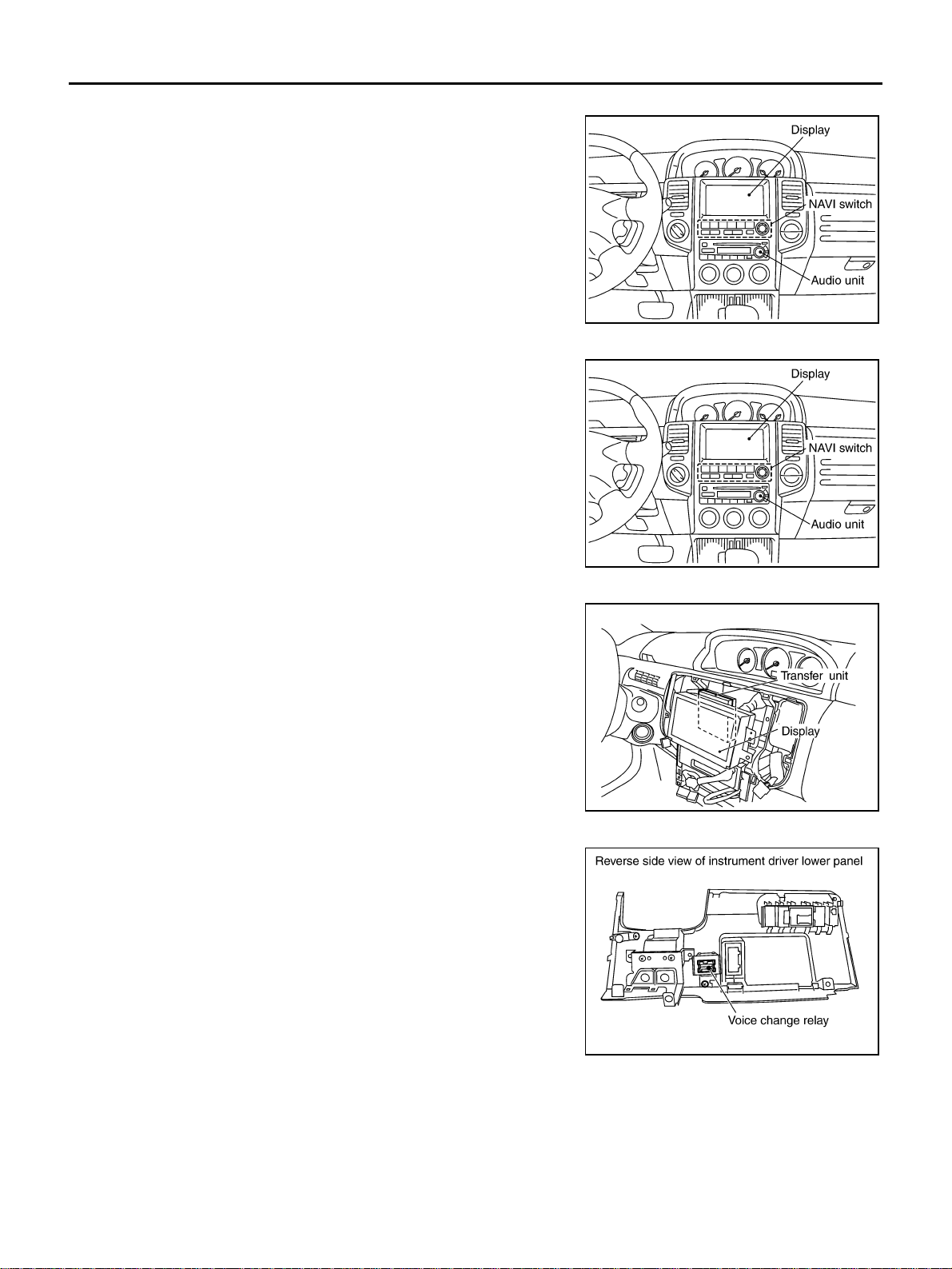
DISPLAY
● Images on the display include RGB image such as map screen.
● NAVI control unit controls images on the display.
NAVI SWITCH
● NAVI switch connects to the display with communication lines.
● Communication form of the operation signal is conversed in dis-
play to NAVI switch. The operation signal is transmit ted to NAVI
control unit.
SKIB6775E
TRANSFER UNIT
● Transfer unit connects to the NAVI control unit with comunication
lines.
● Transfer unit outputs ON signal and voice guidance signal to
voice change relay.
VOICE CHANGE RELAY
Voice change relay converses the audio signal transmitted from
audio unit and the voice gu idan ce sig nal tran smi tted from NAVI control unit through transfer unit. And voice change relay outputs the
audio signal an d the voice guidance signal to driver-side speaker.
SKIB6775E
SKIB6776E
SKIB6786E
Revision: 2006 July 2006 X-Trail
AV-20
Loading...