


 Loading...
K ELECTRICAL
SECTION LT
LIGHTING SYSTEM
CONTENTS
A
B
C
D
E
PRECAUTIONS ......................................................... |
|
3 |
Precautions for Supplemental Restraint System |
|
|
(SRS) “AIR BAG” and “SEAT BELT PRE-TEN- |
|
|
SIONER” ................................................................. |
|
3 |
General Precautions for Service Operations ........... |
|
3 |
HEADLAMP - DAYTIME LIGHT SYSTEM - .............. |
|
4 |
ComponentPartsandHarnessConnectorLocation..... |
4 |
|
System Description ................................................. |
|
5 |
DESCRIPTION ..................................................... |
|
5 |
OUTLINE .............................................................. |
|
5 |
DAYTIME LIGHT OPERATION ............................ |
|
5 |
HEADLAMP OPERATION (DAYTIME LIGHT |
|
|
CANCEL OPERATION) ....................................... |
|
6 |
DRIVING LAMP OPERATION ............................. |
|
6 |
OPERATION TABLE ............................................ |
|
7 |
Schematic ............................................................... |
|
8 |
Wiring Diagram — H/LAMP — ............................ |
..... 9 |
|
Terminals and Reference Value for Daytime Light |
|
|
Control Unit ........................................................... |
|
14 |
Trouble Diagnoses (Daytime Light System) .......... |
|
15 |
Check Daytime Light Relay ................................... |
|
17 |
Trouble Diagnoses (Driving Lamp) ........................ |
|
18 |
Aiming Adjustment of Headlamp ........................... |
|
19 |
PREPARATION BEFORE ADJUSTING ............. |
|
19 |
LOW BEAM AND HIGH BEAM .......................... |
|
19 |
Aiming Adjustment of Driving Lamp ...................... |
|
20 |
PREPARATION BEFORE ADJUSTING ............. |
|
20 |
ADJUSTMENT USING AN ADJUSTMENT |
|
|
SCREEN (LIGHT/DARK BORDERLINE) ........... |
|
20 |
ADJUSTING ....................................................... |
|
21 |
Bulb Replacement ................................................. |
|
21 |
HEADLAMP ....................................................... |
|
21 |
DRIVING LAMP ................................................. |
|
21 |
Removal and Installation of Headlamp ................. |
|
22 |
REMOVAL .......................................................... |
|
22 |
INSTALLATION .................................................. |
|
22 |
Removal and Installation of Driving Lamp ............. |
|
22 |
REMOVAL .......................................................... |
|
23 |
INSTALLATION .................................................. |
|
23 |
Removal and Installation for Driving Lamp Switch... |
23 |
|
TURN SIGNAL AND HAZARD WARNING LAMPS... |
24 |
|
System Description ................................................ |
|
24 |
TURN SIGNAL OPERATION ............................. |
|
24 |
HAZARD LAMP OPERATION ............................ |
|
25 |
Wiring Diagram — TURN — ................................ |
... 26 |
|
Trouble Diagnoses ................................................ |
|
28 |
Electrical Components Inspection ......................... |
|
28 |
COMBINATION FLASHER UNIT CHECK .......... |
|
28 |
HAZARD SWITCH CHECK ................................ |
|
29 |
Bulb Replacement ................................................. |
|
29 |
FRONT TURN SIGNAL LAMP ........................... |
|
29 |
SIDE TURN SIGNAL LAMP ............................... |
|
29 |
REAR TURN SIGNAL LAMP ............................. |
|
29 |
Removal and Installation of Front Turn Signal Lamp... |
29 |
|
Removal and Installation of Side Turn Signal Lamp... |
29 |
|
REMOVAL .......................................................... |
|
29 |
INSTALLATION .................................................. |
|
30 |
Removal and Installation of Rear Turn Signal Lamp... |
30 |
|
LIGHTING AND TURN SIGNAL SWITCH ............... |
|
31 |
Removal and Installation ....................................... |
|
31 |
REMOVAL .......................................................... |
|
31 |
INSTALLATION .................................................. |
|
31 |
HAZARD SWITCH ................................................... |
|
32 |
Removal and Installation ....................................... |
|
32 |
REMOVAL .......................................................... |
|
32 |
INSTALLATION .................................................. |
|
32 |
STOP LAMP ............................................................. |
|
33 |
Wiring Diagram — STOP/L — ............................. |
... 33 |
|
Bulb Replacement ................................................. |
|
34 |
STOP LAMP ....................................................... |
|
34 |
HIGH-MOUNTED STOP LAMP .......................... |
|
34 |
Removal and Installation of Stop Lamp ................. |
|
34 |
Removal and Installation of High-Mounted Stop |
|
|
Lamp ...................................................................... |
|
34 |
REMOVAL .......................................................... |
|
34 |
INSTALLATION .................................................. |
|
34 |
BACK-UP LAMP ...................................................... |
|
35 |
Wiring Diagram — BACK/L — ............................. |
... 35 |
|
Bulb Replacement ................................................. |
|
36 |
Removal and Installation ....................................... |
|
36 |
F
G
H
I
J
LT
L
M
Revision: 2006 July |
LT-1 |
2006 X-Trail |

PARKING, LICENSE PLATE AND TAIL LAMPS ..... |
37 |
Wiring Diagram — TAIL/L — ............................... |
... 37 |
Bulb Replacement ................................................. |
39 |
PARKING LAMP ................................................. |
39 |
LICENSE PLATE LAMP ..................................... |
39 |
TAIL LAMP ......................................................... |
39 |
Removal and Installation of Parking Lamp ............ |
39 |
REMOVAL .......................................................... |
39 |
INSTALLATION ................................................... |
39 |
Removal and Installation of License Plate Lamp |
... 40 |
REMOVAL .......................................................... |
40 |
INSTALLATION ................................................... |
40 |
Removal and Installation of Tail Lamp ................... |
40 |
SIDE MARKER LAMP ............................................. |
41 |
Bulb Replacement ................................................. |
41 |
FRONT SIDE MARKER LAMP ........................... |
41 |
REAR SIDE MARKER LAMP ............................. |
41 |
RemovalandInstallationofFrontSideMarkerLamp... 42 |
|
REMOVAL .......................................................... |
42 |
INSTALLATION ................................................... |
42 |
Removal andInstallationofRear SideMarker Lamp... 42 |
|
REMOVAL .......................................................... |
42 |
INSTALLATION ................................................... |
42 |
FRONT FOG LAMP ................................................. |
43 |
System Description ................................................ |
43 |
DESCRIPTION ................................................... |
43 |
FOG LAMP OPERATION ................................... |
43 |
Wiring Diagram — F/FOG — ............................... |
... 44 |
Aiming Adjustment ................................................. |
45 |
Bulb Replacement ................................................. |
46 |
Removal and Installation ....................................... |
46 |
REMOVAL .......................................................... |
46 |
INSTALLATION ................................................... |
46 |
HIGH-MOUNTED STOP LAMP ............................... |
47 |
Bulb Replacement ................................................. |
47 |
Removal and Installation ....................................... |
47 |
REAR COMBINATION LAMP .................................. |
48 |
Bulb Replacement ................................................. |
48 |
Removal and Installation ....................................... |
48 |
REMOVAL .......................................................... |
48 |
INSTALLATION ................................................... |
48 |
COMBINATION SWITCH .......................................... |
49 |
Removal and Installation ....................................... |
49 |
Switch Circuit Inspection ....................................... |
49 |
INTERIOR ROOM LAMP ......................................... |
50 |
System Description ................................................ |
50 |
POWER SUPPLY AND GROUND ...................... |
50 |
SWITCH OPERATION ........................................ |
51 |
BATTERY SAVER ............................................... |
52 |
Schematic .............................................................. |
53 |
Wiring Diagram —ROOM/L— .............................. |
...54 |
Interior Room Lamp Timer Does Not Operate ....... |
58 |
Interior Room Lamp Timer Does Not Cancel ......... |
61 |
Bulb Replacement .................................................. |
63 |
INTERIOR ROOM LAMP .................................... |
63 |
LUGGAGE ROOM LAMP ................................... |
63 |
Removal and Installation of Interior Room Lamp . |
..63 |
REMOVAL ........................................................... |
63 |
INSTALLATION ................................................... |
63 |
Removal and Installation of Luggage Room Lamp...63 |
|
STEP LAMP ............................................................. |
64 |
Wiring Diagram — STEP/L — .............................. |
...64 |
Bulb Replacement .................................................. |
65 |
Removal and Installation ........................................ |
65 |
REMOVAL ........................................................... |
65 |
INSTALLATION ................................................... |
65 |
MAP LAMP ............................................................... |
66 |
Wiring Diagram —INT/L— ................................... |
...66 |
Bulb Replacement .................................................. |
67 |
MAP LAMP (WITHOUT SUNROOF) .................. |
67 |
MAP LAMP (WITH SUNROOF) .......................... |
67 |
Removal and Installation of Map Lamp (Without |
|
Sunroof) .................................................................. |
67 |
REMOVAL ........................................................... |
67 |
INSTALLATION ................................................... |
67 |
Removal and Installation of Map Lamp (With Sun- |
|
roof) ......................................................................... |
67 |
REMOVAL ........................................................... |
67 |
INSTALLATION ................................................... |
67 |
ILLUMINATION ......................................................... |
68 |
System Description ................................................ |
68 |
Schematic .............................................................. |
69 |
Wiring Diagram -ILL- .............................................. |
70 |
BULB SPECIFICATIONS ......................................... |
74 |
Headlamp ............................................................... |
74 |
Exterior Lamp ......................................................... |
74 |
Interior Lamp/Illumination ....................................... |
74 |
Revision: 2006 July |
LT-2 |
2006 X-Trail |
|
PRECAUTIONS |
|
|
|
|
|
|
PRECAUTIONS |
PFP:00011 |
A |
|
Precautions for Supplemental Restraint System (SRS) “AIR BAG” and “SEAT |
|||
|
|||
BELT PRE-TENSIONER” |
AKS00FD1 |
|
|
The Supplemental Restraint System such as “AIR BAG” and “SEAT BELT PRE-TENSIONER”, used along B |
||
with a front seat belt, helps to reduce the risk or severity of injury to the driver and front passenger for certain |
|
|
types of collision. Information necessary to service the system safely is included in the SRS and SB section of |
|
|
this Service Manual. |
C |
|
WARNING: |
||
|
||
●To avoid rendering the SRS inoperative, which could increase the risk of personal injury or death in the event of a collision which would result in air bag inflation, all maintenance must be per-
formed by an authorized NISSAN/INFINITI dealer.
●Improper maintenance, including incorrect removal and installation of the SRS, can lead to personal injury caused by unintentional activation of the system. For removal of Spiral Cable and Air
Bag Module, see the SRS section.
●Do not use electrical test equipment on any circuit related to the SRS unless instructed to in this Service Manual. SRS wiring harnesses can be identified by yellow and/or orange harnesses or
harness connectors.
General Precautions for Service Operations
●Never work with wet hands.
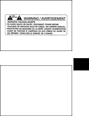
●Xenon headlamp includes high voltage generating part. Be sure to disconnect battery negative cable (negative terminal) or power fuse before removing, installing, or touching the xenon headlamp (including lamp bulb).
●Turn the lighting switch OFF before disconnecting and connecting the connector.
●When turning the xenon headlamp on and while it is illuminated, never touch the harness, bulb, and socket of the headlamp.
●When checking the headlamp on/off operation, check it on vehicle and with the power connected to the vehicle-side connector.
AKS00FCZ
PKIB7344E
●Do not touch the headlamp bulb glass surface with bare hands or allow oil or grease to get on it. Do not touch the headlamp bulb just after the headlamp is turned off, because it is very hot.
● Install the xenon headlamp bulb socket correctly. If it is installed |
|
improperly, high-voltage leak or corona discharge may occur |
|
that can melt the bulb, connector, and housing. Do not illuminate |
|
the xenon headlamp bulb out of the headlamp housing. Doing |
|
so can cause fire and harm your eyes. |
|
● When the bulb has burned out, wrap it in a thick vinyl bag and |
|
discard. Do not break the bulb. |
|
● Leaving the bulb removed from the headlamp housing for a long |
|
period of time can deteriorate the performance of the lens and |
|
reflector (dirt, clouding). Always prepare a new bulb and have it |
|
on hand when replacing the bulb. |
EL-3422D |
●When adjusting the headlamp aiming, turn the aiming adjust-
ment screw only in the tightening direction. (If it is necessary to loosen the screw, first fully loosen the screw, and then turn it in the tightening direction.)
●Do not use organic solvent (paint thinner or gasoline) to clean lamps and to remove old sealant.
D
E
F
G
H
I
J
LT
L
M
Revision: 2006 July |
LT-3 |
2006 X-Trail |

HEADLAMP - DAYTIME LIGHT SYSTEM -
HEADLAMP - DAYTIME LIGHT SYSTEM -
Component Parts and Harness Connector Location
PFP:26010
AKS00BPX
SKIB6790E
*: With driving lamp
Revision: 2006 July |
LT-4 |
2006 X-Trail |

HEADLAMP - DAYTIME LIGHT SYSTEM -
System Description |
AKS00BPJ |
DESCRIPTION |
A |
●Daytime light system is a system that turns on HIGH beam as dimmer blinking automatically while driving with lighting switch OFF or 1ST position (including temporary stop at an intersection).
● HIGH beam dimmer blinks automatically reducing the amount of light when starting engine and taking off the parking brake.
● Daytime light system does not start unless the parking brake is turned off (drive theater mode).
● Daytime light system is not released by putting on the parking brake when making a stop at an intersection.
● Put on the parking brake, stop the engine, and restart the engine to select drive theater mode. ● Daytime light system stops when shifting lighting switch to the 2ND or PASS position.
●Daytime light control unit performs dimmer blinking, opening the circuit that connects bilateral HIGH beams in series.
OUTLINE
Power is supplied at all times
●through 15A fuse (No. 40, located in fuse and fusible link box)
●to daytime light control unit terminal 3
●to combination switch (lighting switch) terminal 8 and
●to daytime light relay LH terminal 5
●through 15A fuse (No. 41, located in fuse and fusible link box)
●to daytime light control unit terminal 2
●to combination switch (lighting switch) terminal 5 and
●to daytime light relay RH terminal 5.
When the ignition switch is ON or START position, power is supplied
●through 10A fuse [No.13, located in fuse block (J/B)]
●to daytime light control unit terminal 12
●through 10A fuse [No.11, located in fuse block (J/B)]
●to combination meter (charge) terminal 2.
When the ignition switch is START position, power is supplied
●through 10A fuse [No.7, located in fuse block (J/B)]
●to daytime light control unit terminal 1.
Ground is supplied
●to daytime light control unit terminal 9
●to headlamp RH terminal 2
●to daytime light relay LH terminal 2
●to daytime light relay RH terminal 2 and
●through grounds E24 and E50
●to combination meter (HIGH beam indicator) terminal 19
●through grounds M27 and M70.
DAYTIME LIGHT OPERATION
With the engine running, the lighting switch is OFF or 1ST position and parking brake released, the daytime light control unit controls internal relay. When internal relay, power is supplied
●through daytime light control unit terminal 6
●to headlamp LH terminal 1
●through headlamp LH terminal 2
●to daytime light control unit terminal 7
●through daytime light control unit terminal 8
●to headlamp RH terminal 1.
B
C
D
E
F
G
H
I
J
LT
L
M
Revision: 2006 July |
LT-5 |
2006 X-Trail |

HEADLAMP - DAYTIME LIGHT SYSTEM -
Ground is supplied
●to headlamp RH terminal 2
●through grounds E24 and E50.
With power and grounds supplied, the daytime light illuminate. The HIGH beam headlamps are now wired in series and illuminate at a reduce intensity.
HEADLAMP OPERATION (DAYTIME LIGHT CANCEL OPERATION)
HEADLAMP RH
When the combination switch (lighting switch) is turned to the 2ND position and placed in LOW position, power is supplied
●from combination switch (lighting switch) terminal 7
●to headlamp RH terminal 3.
When the combination switch (lighting switch) is turned to the 2ND position and placed in HIGH or PASS position, power is supplied
●from combination switch (lighting switch) terminal 6
●to daytime light relay RH terminal 1
●through daytime light relay RH terminal 3
●to headlamp RH terminal 1.
HEADLAMP LH
When the combination switch (lighting switch) is turned to the 2ND position and placed in LOW position, power is supplied
●from combination switch (lighting switch) terminal 10
●to daytime light relay LH terminal 1
●through daytime light relay LH terminal 3
●to headlamp LH terminal 3.
When the combination switch (lighting switch) is turned to the 2ND position and placed in HIGH or PASS position, power is supplied
●from combination switch (lighting switch) terminal 9
●to daytime light control unit terminal 5
●through daytime light control unit terminal 6
●to headlamp LH terminal 1.
At the same time, power is supplied
●from combination switch (lighting switch) terminal 9
●to combination meter (HIGH beam indicator) terminal 20, and then indicator illuminates.
When the combination switch is shifted to HIGH or PASS, daytime light system is released after the signal is sent to the daytime light control unit terminal 5.
Also, when the combination switch is shifted to LOW, daytime light system is released after the signal is sent to the daytime control unit terminal 4.
DRIVING LAMP OPERATION
To illuminate the driving lamp, push the driving lamp switch when the lighting switch is turned to the 2ND position and placed in HIGH BEAM position or PASSING position, power is supplied
●through combination switch (lighting switch) terminal 9
●to combination meter (HIGH beam indicator) terminal 20
●to driving lamp relay-1 terminal 1
●to driving lamp switch terminal 7
●to driving lamp relay-2 terminal 5 and
●to daytime light control unit terminal 5
●through daytime light control unit terminal 6
●to headlamp LH terminal 1
●through combination switch (lighting switch) terminal 6
●to daytime light relay RH terminal 1
Revision: 2006 July |
LT-6 |
2006 X-Trail |

HEADLAMP - DAYTIME LIGHT SYSTEM -
●through daytime light relay RH terminal 3
●to headlamp RH terminal 1,
●through driving lamp relay-2 terminal 3
●to driving lamp switch terminal 6,
●through driving lamp relay-1 terminal 5
●to driving lamp LH and RH terminals 2. Ground is supplied
●to driving lamp relay-1 terminal 2
●through driving lamp relay-2 terminal 7
●through driving lamp relay-2 terminal 6
●through grounds E24 and E50,
●to driving lamp switch terminal 4
●through driving lamp relay-2 terminal 1
●through driving lamp relay-2 terminal 2
●through grounds E24 and E50,
●to driving lamp LH terminal 1
●through ground R8,
●to driving lamp RH terminals 1 and 3
●through ground R8,
●to headlamp LH terminal 2
●through daytime light control unit terminal 7
●through daytime light control unit terminal 9
●through grounds E24 and E50,
●to headlamp RH terminal 2
●through grounds E24 and E50,
●to combination meter (HIGH beam indicator) terminal 19
●through grounds M27 and M70.
With power and ground supplied, high beam headlamps, driving lamp and the HIGH BEAM indicator illuminate.
OPERATION TABLE
Engine |
|
|
|
Engine stopped |
|
|
|
|
|
|
|
|
Engine running |
|
|
|
|
|
|||||
|
|
|
|
|
|
|
|
|
|
|
|
|
|
|
|
|
|
|
|
|
|
||
Lighting switch |
|
OFF |
|
|
1ST |
|
|
|
2ND |
|
OFF |
|
|
1ST |
|
|
|
2ND |
|||||
|
|
|
|
|
|
|
|
|
|
|
|
|
|
|
|
|
|
|
|
|
|
||
|
|
Hi |
Lo |
P |
Hi |
Lo |
P |
Hi |
|
Lo |
|
P |
Hi |
Lo |
P |
Hi |
Lo |
P |
Hi |
|
Lo |
|
P |
|
|
|
|
|
|
|
|
|
|
|
|
|
|
|
|
|
|
|
|
|
|
|
|
Headlamp |
HIGH beam |
– |
– |
× |
– |
– |
× |
× |
|
– |
|
× |
●* |
●* |
× |
●* |
●* |
× |
× |
|
– |
|
× |
|
|
|
|
|
|
|
|
|
|
|
|
|
|
|
|
|
|
|
|
|
|
|
|
LOW beam |
– |
– |
– |
– |
– |
– |
– |
|
× |
|
– |
– |
– |
– |
– |
– |
– |
– |
|
× |
|
– |
|
|
|
|
|
|
|||||||||||||||||||
|
|
|
|
|
|
|
|
|
|
|
|
|
|
|
|
|
|
|
|
|
|
|
|
Parking (clearance), side marker |
– |
– |
– |
× |
× |
× |
× |
× |
× |
|
– |
– |
– |
× |
× |
× |
× |
× |
× |
|
|||
and tail lamp |
|
|
|||||||||||||||||||||
|
|
|
|
|
|
|
|
|
|
|
|
|
|
|
|
|
|
|
|
|
|
||
|
|
|
|
|
|
|
|
|
|
|
|
|
|
|
|
|
|
|
|
|
|
|
|
License and instrument illumina- |
– |
– |
– |
× |
× |
× |
× |
× |
× |
|
– |
– |
– |
× |
× |
× |
× |
× |
× |
|
|||
tion lamp |
|
|
|||||||||||||||||||||
|
|
|
|
|
|
|
|
|
|
|
|
|
|
|
|
|
|
|
|
|
|
||
|
|
|
|
|
|
|
|
|
|
|
|
|
|
|
|
|
|
|
|
|
|
|
|
●Hi: “HIGH beam” position
●Lo: “LOW beam” position
●P: “FLASH TO PASS” position
●× : Lamp “ON”
●–: Lamp “OFF”
●●: Lamp dims. (Added functions)
●*: When starting the engine with the parking brake released, the daytime light will come ON. When starting the engine with the parking brake pulled, the daytime light will not come ON.
A
B
C
D
E
F
G
H
I
J
LT
L
M
Revision: 2006 July |
LT-7 |
2006 X-Trail |

HEADLAMP - DAYTIME LIGHT SYSTEM -
Schematic |
AKS00BPK |
TKWB2247E
Revision: 2006 July |
LT-8 |
2006 X-Trail |

HEADLAMP - DAYTIME LIGHT SYSTEM -
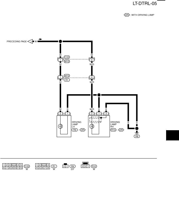
Wiring Diagram — H/LAMP —
AKS00BPL
A
B
C
D
E
F
G
H
I
J
LT
L
M
TKWB0151E
Revision: 2006 July |
LT-9 |
2006 X-Trail |

HEADLAMP - DAYTIME LIGHT SYSTEM -
TKWB2248E
Revision: 2006 July |
LT-10 |
2006 X-Trail |
HEADLAMP - DAYTIME LIGHT SYSTEM -
A
B
C
D
E
F
G
H
I
J
LT
L
M
TKWB0153E
Revision: 2006 July |
LT-11 |
2006 X-Trail |

HEADLAMP - DAYTIME LIGHT SYSTEM -
TKWB2250E
Revision: 2006 July |
LT-12 |
2006 X-Trail |
HEADLAMP - DAYTIME LIGHT SYSTEM -
A
B
C
D
E
F
G
H
I
J
LT
L
M
TKWB2251E
Revision: 2006 July |
LT-13 |
2006 X-Trail |

HEADLAMP - DAYTIME LIGHT SYSTEM -
Terminals and Reference Value for Daytime Light Control Unit |
AKS00BPY |
|||||||
|
|
|
|
|
|
|
|
|
Terminal |
Wire |
Signal name |
Operation or condition |
Reference value |
||||
No. |
color |
|||||||
|
|
|
|
|
|
|||
|
|
|
|
|
|
|
|
|
1 |
B/Y |
Engine start signal |
Ignition switch |
|
START |
Battery voltage |
||
|
|
|
|
|||||
|
ON, ACC or OFF |
Approx. 0V |
||||||
|
|
|
|
|
||||
|
|
|
|
|
|
|
|
|
2 |
R/W |
Power source for headlamp |
|
— |
Battery voltage |
|||
RH |
|
|||||||
|
|
|
|
|
|
|
||
|
|
|
|
|
|
|
|
|
3 |
LG |
Power source for headlamp |
|
— |
Battery voltage |
|||
LH |
|
|||||||
|
|
|
|
|
|
|
||
|
|
|
|
|
|
|
|
|
4 |
G/Y |
Headlamp LOW beam signal |
Lighting switch |
|
LOW |
Approx. 12V |
||
|
|
|
|
|||||
|
Except LOW |
Approx. 0V |
||||||
|
|
|
|
|
||||
|
|
|
|
|
|
|
|
|
5 |
B/R |
Headlamp HIGH beam or |
Lighting switch |
|
HIGH or PASS |
Approx. 12V |
||
|
|
|
|
|||||
PASS signal |
|
|
|
|
||||
|
Except above |
Approx. 0V |
||||||
|
|
|
|
|||||
|
|
|
|
|
||||
|
|
|
|
|
|
|
|
|
6 |
B/R |
Headlamp LH HIGH |
Drive theater mode |
|
|
Approx. 0V |
||
|
|
|
|
|
||||
Lighting switch HIGH, PASS or daytime light operating* |
Approx. 12V |
|||||||
|
|
|
||||||
|
|
|
|
|
|
|
|
|
7 |
L |
Headlamp LH ground |
Daytime light operating* |
|
|
Approx. 6V |
||
|
|
|
|
|
||||
Lighting switch LOW and HIGH position |
Approx. 0V |
|||||||
|
|
|
||||||
|
|
|
|
|
|
|
|
|
|
|
|
Daytime light operating* |
|
|
Approx. 6V |
||
|
|
|
|
|
|
|||
8 |
G/R |
Headlamp RH HIGH |
Lighting switch LOW position |
Approx. 0V |
||||
|
|
|
|
|
|
|||
|
|
|
Lighting switch HIGH position |
Approx. 12V |
||||
|
|
|
|
|
|
|
|
|
9 |
B |
Ground for daytime light con- |
|
— |
Approx. 0V |
|||
trol unit |
|
|||||||
|
|
|
|
|
|
|
||
|
|
|
|
|
|
|
|
|
10 |
PU/W |
Parking brake switch signal |
Brake switch (Ignition |
|
ON |
Approx. 0V |
||
|
|
|
|
|||||
switch is ON) |
|
|
|
|
||||
|
Released |
Approx. 12V |
||||||
|
|
|
|
|||||
|
|
|
|
|
||||
|
|
|
|
|
|
|
|
|
11 |
Y/R |
Alternator “L” terminal |
Engine |
|
Running |
Approx. 12V |
||
|
|
|
|
|||||
|
Stopped |
Approx. 0V |
||||||
|
|
|
|
|
||||
|
|
|
|
|
|
|
|
|
12 |
BR |
Power source for daytime light |
Ignition switch |
|
ON or START |
Battery voltage |
||
|
|
|
|
|||||
control unit |
|
|
|
|
||||
|
Except above |
Approx. 0V |
||||||
|
|
|
|
|||||
|
|
|
|
|
||||
|
|
|
|
|
|
|
|
|
* Daytime light operating: Lighting switch in OFF position with engine running and parking brake is released.
Revision: 2006 July |
LT-14 |
2006 X-Trail |

HEADLAMP - DAYTIME LIGHT SYSTEM -
Trouble Diagnoses (Daytime Light System) |
AKS00BQ5 |
||||||||||
|
|
|
|
|
|
|
|||||
|
Inoperative System (or lamp) |
|
|
|
|
|
|||||
|
|
|
|
|
|
|
|
|
|
|
|
Theater |
Daytime |
LOW |
HIGH |
|
High |
Possible cause |
Repair order |
||||
beam |
beam |
|
|||||||||
|
beam |
||||||||||
|
|
|
|
||||||||
mode |
light |
|
|
|
|
||||||
|
|
|
|
|
|
|
|
|
|||
|
|
|
|
|
|
indicator |
|
|
|
||
|
|
RH |
LH |
RH |
|
LH |
|
|
|
|
|
|
|
|
|
|
|
|
|
||||
|
|
|
|
|
|
|
|
|
|
|
|
|
|
|
|
|
|
|
|
|
● 10A fuse |
● Check 10A fuse [No.11, located in fuse block (J/B)]. |
|
|
|
|
|
|
|
|
|
|
|
● Check harness between 15A fuse (No.41, located in |
|
|
|
|
|
|
|
|
|
|
|
fuse and fusible link box) and daytime light control unit |
|
|
|
|
|
|
|
|
|
|
|
terminal 2. |
|
|
|
|
|
|
|
|
|
|
|
● Check harness between 15A fuse (No.40, located in |
|
|
|
|
|
|
|
|
|
|
|
fuse and fusible link box) and daytime light control unit |
|
|
|
|
|
|
|
|
|
|
● Harness and |
terminal 3. |
|
|
|
|
|
|
|
|
|
|
● Check harness between daytime light control unit ter- |
||
|
|
|
|
|
|
|
|
|
connector |
||
|
|
|
|
|
|
|
|
|
minal 8 and headlamp RH terminal 1. |
||
|
|
|
|
|
|
|
|
|
|
||
|
× |
|
|
|
|
|
|
|
|
● Check harness between daytime light control unit ter- |
|
|
|
|
|
|
|
|
|
|
|
minal 11 and alternator terminal 3. |
|
|
|
|
|
|
|
|
|
|
|
● Check harness between 10A fuse [No.13, located in |
|
|
|
|
|
|
|
|
|
|
|
fuse block (J/B)] and daytime light control unit terminal |
|
|
|
|
|
|
|
|
|
|
|
12. |
|
|
|
|
|
|
|
|
|
|
● parking brake |
● Check parking brake switch. |
|
|
|
|
|
|
|
|
|
|
switch |
||
|
|
|
|
|
|
|
|
|
|
|
|
|
|
|
|
|
|
|
|
|
● Daytime light |
● Check daytime light control unit. Refer to LT-14, "Ter- |
|
|
|
|
|
|
|
|
|
|
minals and Reference Value for Daytime Light Control |
||
|
|
|
|
|
|
|
|
|
control unit |
||
|
|
|
|
|
|
|
|
|
Unit" . |
||
|
|
|
|
|
|
|
|
|
|
||
|
|
|
|
|
|
|
|
|
|
|
|
|
|
|
|
|
|
|
|
|
● Bulb |
● Check headlamp bulb LH (HIGH). |
|
|
|
|
|
|
|
|
|
|
● Harness and |
● Check continuity between daytime light control unit |
|
|
× |
|
|
|
|
× |
|
|
connector |
terminal 6 and headlamp LH terminal 1. |
|
|
|
|
|
|
|
|
|
● Check daytime light control unit. Refer to LT-14, "Ter- |
|||
|
|
|
|
|
|
|
|
|
● Daytime light |
||
|
|
|
|
|
|
|
|
|
minals and Reference Value for Daytime Light Control |
||
|
|
|
|
|
|
|
|
|
control unit |
||
|
|
|
|
|
|
|
|
|
Unit" |
||
|
|
|
|
|
|
|
|
|
|
||
|
|
|
|
|
|
|
|
|
|
|
|
|
× |
|
|
× |
|
|
|
|
● Bulb |
● Check headlamp bulb RH (HIGH). |
|
|
|
|
|
|
|
|
|
|
|
|
|
|
|
|
|
|
|
|
|
|
● Grounds E24 |
● Check grounds E24 and E50. |
|
|
|
|
|
|
|
|
|
|
and E50 |
||
|
|
|
|
|
|
|
|
|
|
|
|
|
|
|
|
|
|
|
|
|
|
● Check continuity between daytime light control unit |
|
|
|
|
|
|
|
|
|
|
● Harness and |
terminal 7 and headlamp LH terminal 2. |
|
|
× |
|
× |
|
× |
|
|
|
connector |
● Check continuity between daytime light control unit |
|
|
|
|
|
|
|
|
|
|
|
terminal 9 and ground. |
|
|
|
|
|
|
|
|
|
|
● Daytime light |
● Check daytime light control unit. Refer to LT-14, "Ter- |
|
|
|
|
|
|
|
|
|
|
minals and Reference Value for Daytime Light Control |
||
|
|
|
|
|
|
|
|
|
control unit |
||
|
|
|
|
|
|
|
|
|
Unit" . |
||
|
|
|
|
|
|
|
|
|
|
||
|
|
|
|
|
|
|
|
|
|
|
|
|
|
|
|
|
|
|
|
|
● 15A fuse |
● Check 15A fuse (No.40, located in fuse and fusible |
|
|
|
|
|
|
|
|
|
|
link box). |
||
|
|
|
|
|
|
|
|
|
|
||
|
× |
|
× |
|
× |
|
× |
● Harness and |
● Check harness between 15A fuse (No.40, located in |
||
|
|
|
|
|
|
|
|
|
fuse and fusible link box) and daytime light control unit |
||
|
|
|
|
|
|
|
|
|
connector |
||
|
|
|
|
|
|
|
|
|
terminal 3. |
||
|
|
|
|
|
|
|
|
|
|
||
|
|
|
|
|
|
|
|
|
|
|
|
|
|
|
|
|
|
|
|
|
● 15A fuse |
● Check 15A fuse (No.41, located in fuse and fusible |
|
|
|
|
|
|
|
|
|
|
link box). |
||
|
|
|
|
|
|
|
|
|
|
||
|
× |
× |
|
× |
|
|
|
|
● Harness and |
● Check harness between 15A fuse (No.41, located in |
|
|
|
|
|
|
|
|
|
|
fuse and fusible link box) and daytime light control unit |
||
|
|
|
|
|
|
|
|
|
connector |
||
|
|
|
|
|
|
|
|
|
terminal 2. |
||
|
|
|
|
|
|
|
|
|
|
||
|
|
|
|
|
|
|
|
|
|
|
|
|
× * |
× |
●** |
× |
|
|
|
|
● Harness and |
● Check continuity between headlamp RH terminal 2 |
|
|
|
|
|
|
connector |
and ground. |
|||||
|
|
|
|
|
|
|
|
|
|||
|
|
|
|
|
|
|
|
|
|
|
|
A
B
C
D
E
F
G
H
I
J
LT
L
M
Revision: 2006 July |
LT-15 |
2006 X-Trail |

HEADLAMP - DAYTIME LIGHT SYSTEM -
|
Inoperative System (or lamp) |
|
|
|
|||||
|
|
|
|
|
|
|
|
|
|
Theater |
Daytime |
LOW |
HIGH |
High |
Possible cause |
Repair order |
|||
beam |
beam |
||||||||
beam |
|||||||||
|
|
||||||||
mode |
light |
|
|
||||||
|
|
|
|
|
|
||||
|
|
|
|
indicator |
|
|
|||
|
|
RH |
LH |
RH |
LH |
|
|
||
|
|
|
|
|
|||||
|
|
|
|
|
|
|
|
|
|
|
|
|
|
|
|
|
● Parking |
● Check parking brake switch. |
|
|
|
|
|
|
|
|
brake switch |
||
|
|
|
|
|
|
|
|
||
|
|
|
|
|
|
|
● Harness and |
● Check continuity between daytime light control unit |
|
× |
|
|
|
|
|
|
connector |
terminal 10 and parking brake switch terminal 1. |
|
|
|
|
|
|
|
|
● Daytime light |
● Check daytime light control unit. Refer to LT-14, "Ter- |
|
|
|
|
|
|
|
|
minals and Reference Value for Daytime Light Control |
||
|
|
|
|
|
|
|
control unit |
||
|
|
|
|
|
|
|
Unit" . |
||
|
|
|
|
|
|
|
|
||
|
|
|
|
|
|
|
|
|
|
|
|
|
|
|
|
|
● Bulb |
● Check headlamp bulb LH (LOW). |
|
|
|
|
|
|
|
|
● Combination |
● Check combination switch. Refer to LT-49, "Switch |
|
|
|
|
|
|
|
|
switch |
Circuit Inspection" . |
|
|
|
|
|
|
|
|
|
● Check continuity between combination switch terminal |
|
|
|
|
|
|
|
|
|
10 and daytime light relay LH terminal 1. |
|
|
|
|
|
|
|
|
● Harness and |
● Check continuity between daytime light relay LH ter- |
|
|
|
|
× |
|
|
|
connector |
minal 2 and ground. |
|
|
|
|
|
|
|
|
● Check continuity between combination switch terminal |
||
|
|
|
|
|
|
|
|
||
|
|
|
|
|
|
|
|
7 and daytime light control unit terminal 4. |
|
|
|
|
|
|
|
|
● Daytime light |
● Check daytime light relay LH. Refer to LT-17, "Check |
|
|
|
|
|
|
|
|
relay LH |
Daytime Light Relay" . |
|
|
|
|
|
|
|
|
● Daytime light |
● Check daytime light control unit. Refer to LT-14, "Ter- |
|
|
|
|
|
|
|
|
minals and Reference Value for Daytime Light Control |
||
|
|
|
|
|
|
|
control unit |
||
|
|
|
|
|
|
|
Unit" . |
||
|
|
|
|
|
|
|
|
||
|
|
|
|
|
|
|
|
|
|
|
|
× |
|
|
|
|
● Bulb |
● Check headlamp bulb RH (LOW). |
|
|
|
|
|
|
|
|
|
|
|
|
|
|
|
|
|
|
● Harness and |
● Check continuity between combination switch terminal |
|
|
|
|
|
|
|
|
connector |
9 and daytime light control unit terminal 5. |
|
|
|
|
|
|
× |
|
● Daytime light |
● Check daytime light control unit. Refer to LT-14, "Ter- |
|
|
|
|
|
|
|
|
minals and Reference Value for Daytime Light Control |
||
|
|
|
|
|
|
|
control unit |
||
|
|
|
|
|
|
|
Unit" . |
||
|
|
|
|
|
|
|
|
||
|
|
|
|
|
|
|
|
|
|
|
|
|
|
|
|
|
|
● Check voltage between combination switch terminal 6 |
|
|
|
|
|
|
|
|
● Combination |
and ground. |
|
|
|
|
|
|
|
|
switch |
● Check combination switch. Refer to LT-49, "Switch |
|
|
|
|
|
|
|
|
|
Circuit Inspection" . |
|
|
|
|
|
× |
|
|
|
● Check continuity between combination switch terminal |
|
|
|
|
|
|
|
● Harness and |
6 and daytime light relay RH terminal 1. |
||
|
|
|
|
|
|
|
|||
|
|
|
|
|
|
|
connector |
● Check continuity between daytime light relay RH ter- |
|
|
|
|
|
|
|
|
|
minal 2 and ground. |
|
|
|
|
|
|
|
|
● Daytime light |
● Check daytime light relay RH. Refer to LT-17, "Check |
|
|
|
|
|
|
|
|
relay RH |
Daytime Light Relay" . |
|
|
|
|
|
|
|
|
|
|
|
|
|
|
|
|
|
|
|
● Check voltage between combination switch terminal 7 |
|
|
|
|
|
|
|
|
● Combination |
and ground. |
|
|
|
|
●** |
|
|
|
switch |
● Check combination switch. Refer to LT-49, "Switch |
|
|
|
|
|
|
|
|
Circuit Inspection" . |
||
|
|
|
|
|
|
|
|
||
|
|
|
|
|
|
|
● Harness and |
● Check continuity between combination switch terminal |
|
|
|
|
|
|
|
|
connector |
7 and headlamp RH terminal 3. |
|
|
|
|
|
|
|
|
|
|
|
|
|
|
|
|
|
|
|
● Check voltage between combination switch terminal 5 |
|
|
|
|
|
|
|
|
● Combination |
and ground. |
|
|
|
|
|
|
|
|
switch |
● Check combination switch. Refer to LT-49, "Switch |
|
|
|
|
●** |
× |
|
|
|
Circuit Inspection" . |
|
|
|
|
|
|
|
|
● Harness and |
● Check continuity between 15A fuse (No.41, located in |
|
|
|
|
|
|
|
|
fuse and fusible link box) and combination switch ter- |
||
|
|
|
|
|
|
|
connector |
||
|
|
|
|
|
|
|
minal 5. |
||
|
|
|
|
|
|
|
|
||
|
|
|
|
|
|
|
|
|
|
Revision: 2006 July |
LT-16 |
2006 X-Trail |

HEADLAMP - DAYTIME LIGHT SYSTEM -
|
Inoperative System (or lamp) |
|
|
|
|
||||
|
|
|
|
|
|
|
|
|
|
Theater |
Daytime |
LOW |
HIGH |
|
High |
Possible cause |
Repair order |
||
beam |
beam |
|
|||||||
|
beam |
||||||||
|
|
|
|||||||
mode |
light |
|
|
|
|||||
|
|
|
|
|
|
|
|||
|
|
|
|
|
indicator |
|
|
||
|
|
RH |
LH |
RH |
LH |
|
|
|
|
|
|
|
|
|
|
||||
|
|
|
|
|
|
|
|
|
|
|
|
|
|
|
|
|
|
|
● Check voltage between combination switch terminal 9 |
|
|
|
|
|
|
|
|
● Combination |
and ground. |
|
|
|
|
|
× |
× |
switch |
● Check combination switch. Refer to LT-49, "Switch |
|
|
|
|
|
|
|
Circuit Inspection" . |
|||
|
|
|
|
|
|
|
|
|
|
|
|
|
|
|
|
|
|
● Harness and |
● Check continuity between combination switch terminal |
|
|
|
|
|
|
|
|
connector |
9 and combination meter terminal 20. |
|
|
|
|
|
|
|
|
|
|
|
|
|
|
|
|
|
|
|
● Check voltage between combination switch terminal 8 |
|
|
|
|
|
|
|
|
● Combination |
and ground. |
|
|
|
|
|
|
|
|
switch |
● Check combination switch. Refer to LT-49, "Switch |
|
|
|
× |
|
× |
× |
|
Circuit Inspection" . |
|
|
|
|
|
|
|
|
|
● Harness and |
● Check continuity between 15A fuse (No.40, located in |
|
|
|
|
|
|
|
|
fuse and fusible link box) and combination switch ter- |
|
|
|
|
|
|
|
|
|
connector |
|
|
|
|
|
|
|
|
|
minal 8. |
|
|
|
|
|
|
|
|
|
|
|
|
|
|
|
|
|
|
|
|
|
*: Chattering noise can be heard from daytime light control unit when daytime light system is ON. **: ● shows a condition that a lamp is lighted quite dimly.
Check Daytime Light Relay |
AKS00C3G |
1.Apply battery voltage to between terminal 1 and 2.
2.Check continuity between terminal 3 and 5.
3 – 5 |
:Continuity should exist. |
PKIA5214E
A
B
C
D
E
F
G
H
I
J
LT
L
M
Revision: 2006 July |
LT-17 |
2006 X-Trail |

HEADLAMP - DAYTIME LIGHT SYSTEM -
Trouble Diagnoses (Driving Lamp) |
AKS00FN8 |
||
|
|
|
|
Symptom |
Possible cause |
Repair order |
|
|
|
|
|
|
|
1. Check 15A fuse (No. 38, located in fuse and fusible link |
|
|
|
box). |
|
|
|
Check voltage between driving lamp relay-1 terminal 3 |
|
|
|
and ground. |
|
|
|
2. Check continuity between lighting switch terminal 9 and |
|
|
|
driving lamp switch terminal 7 for an open circuit. |
|
|
1. 15A fuse |
3. Check driving lamp switch. |
|
|
4. Check driving lamp relay-2. |
||
|
2. Open in driving lamp switch |
||
|
5. Check continuity between driving lamp switch terminal 4 |
||
|
3. Driving lamp switch circuit |
||
|
and driving lamp relay-2 terminal 1 for an open circuit. |
||
|
4. Driving lamp relay-2 |
||
|
Check continuity between driving lamp switch terminal 6 |
||
|
|
||
Driving lamp does not operate |
5. Open in driving lamp relay-2 circuit |
and driving lamp relay-2 terminal 3 for an open circuit. |
|
|
Check continuity between lighting switch terminal 9 and |
||
(both side), but high beam |
6. Grounds E24 and E50 |
||
driving lamp relay-2 terminal 5 for an open circuit. |
|||
operates. |
7. Driving lamp relay-1 |
||
Check continuity between driving lamp relay-1 terminal 2 |
|||
|
|||
|
8. Open in driving lamp relay-1 circuit |
||
|
and driving lamp relay-2 terminal 7 for an open circuit. |
||
|
9. Open driving lamp circuit |
6. Check grounds E24 and E50. |
|
|
10.Ground R8 |
7. Check driving lamp relay-1. |
|
|
11.Bulb |
8. Check continuity between lighting switch terminal 9 and |
|
|
|
driving lamp relay-1 terminal 1 for an open circuit. |
|
|
|
9. Check continuity between driving lamp relay-1 terminal 5 |
|
|
|
and driving lamp (LH and RH) terminal 2 for an open cir- |
|
|
|
cuit. |
|
|
|
10.Check ground R8. |
|
|
|
11.Check bulbs. |
|
|
|
|
|
|
|
1. Check bulb of lamp which does not illuminate. |
|
Driving lamp does not operate |
1. Bulb |
2. Check ground R8. |
|
|
|||
(one side), but high beam |
2. Ground R8 |
3. Check continuity between driving lamp relay-1 terminal 5 |
|
operates. |
|
||
3. Open driving lamp circuit |
and driving lamp (LH or RH) terminal 2 for an open cir- |
||
|
|||
|
|
cuit. |
|
|
|
|
|
Revision: 2006 July |
LT-18 |
2006 X-Trail |
HEADLAMP - DAYTIME LIGHT SYSTEM -
Aiming Adjustment of Headlamp |
AKS00FN9 |
PREPARATION BEFORE ADJUSTING |
A |
For details, refer to the regulations in your country.
Before performing aiming adjustment, check the following.
●Keep all tires inflated to correct pressures.
●Place vehicle and tester on one and same flat surface.
●See that there is no-load in vehicle (coolant, engine oil filled up to correct level and full fuel tank) other
than the driver (or equivalent weight placed in driver's position).
LOW BEAM AND HIGH BEAM
1.Turn headlamp low beam on.
2.Use aiming adjustment screws to perform aiming adjustment.
NOTE:
Vertical side must be adjusted finally, if horizontal side has been adjusted.
PKIA9589E
B
C
D
E
F
G
H
● First tighten aiming adjustment screw all the way and then make adjustment by loosening the screw.
If the vehicle front body has been repaired and/or the headlamp assembly has been replaced, check aiming. Use the aiming chart shown in the figure.
●Adjust headlamps so that main axis of light is parallel to center line of body and is aligned with point P shown in the figure.
●Figure shows headlamp aiming pattern for driving on right side of road; for driving on left side of road, aiming pattern is reversed.
●Dotted lines to point P in the figure show center of headlamp.
"H" |
: Horizontal center line of headlamps |
"WL " |
: Distance between each headlamp center |
"L" |
: 10,000 mm (393.70 in) |
"C" |
: 135 mm (5.31 in) |
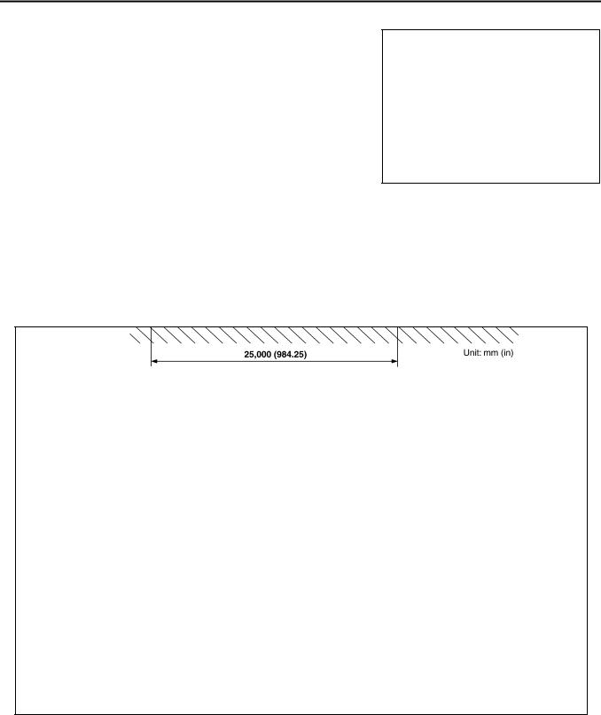
●Basic illuminating area for adjustment should be within the range shown in the figure. Adjust headlamps accordingly.
PKIA9738E
I
J
LT
L
M
Revision: 2006 July |
LT-19 |
2006 X-Trail |
HEADLAMP - DAYTIME LIGHT SYSTEM -
Aiming Adjustment of Driving Lamp |
AKS00FNA |
●Turn aiming adjusting screw to adjust.
●For positions of adjusting screws and direction to turn, refer to the figures.
●When adjusting horizontal direction (right and left), turn two adjusting screws to the same direction.
PKIA3394E
PREPARATION BEFORE ADJUSTING
For Details, Refer To The Regulations In Your Own Country.
Before performing aiming adjustment, check the following.
1.Keep all tires inflated to correct pressures.
2.Place vehicle on flat surface.
3.Set that there is no-load in vehicle other than the driver (or equivalent weight placed in driver's position). Coolant, engine oil filled up to correct level and full fuel tank.
ADJUSTMENT USING AN ADJUSTMENT SCREEN (LIGHT/DARK BORDERLINE)
SKIB7014E
Revision: 2006 July |
LT-20 |
2006 X-Trail |
HEADLAMP - DAYTIME LIGHT SYSTEM -
ADJUSTING
1. |
Set the distance between the screen and the center of the driving lamp lens as shown in the figure. |
||
2. |
Turn head lamp switch high and driving lamp switch ON so that front driving lamps turn ON. |
|
|
3. |
Adjust driving lamps using adjusting screws make sure of the following. |
|
|
|
● |
When performing this adjustment, cover the headlamps and the opposite driving lamp, if necessary. |
|
|
● |
Vertical deflection of maximum illuminance point to be adjusted to stand at 218mm (8.58in) below driv- |
|
|
|
ing lamp height (h). |
|
|
● |
Horizontal deflection of maximum illuminance point to be adjusted to stand within 0 ± |
218mm (0 ± |
|
|
8.58in) against line (V) on screen where a line passing through driving lamp center, parallel to vehicle |
|
|
|
center line, cross screen. |
|
Bulb Replacement |
AKS00FNB |
||
HEADLAMP
1.Disconnect headlamp connector.
2.Remove rubber cap.
3.Unlock retaining spring, then remove bulb.
4.Installation is the reverse of removal.
Headlamp (High/Low) |
: 12V - 60/55W (H4) |
PKIA8616E
CAUTION:
● |
Do not touch glass of bulb directly by hand. Keep grease and other oily matters away from it. |
● |
Do not touch bulb by hand while it is lit or right after being turned off. Burning may result. |
● |
When replacing bulb, prepare new bulb first of all. Do not leave bulb out of headlamp housing |
|
for a long period, because dust, moisture, or smoke will cause performance lowering (fouling, |
|
cloud, etc.) of headlamp reflector and lens. |
● |
When bulb is installed, be sure to lock rubber cap to ensure watertightness. |
DRIVING LAMP
1.Remove driving lamp. Refer to LT-22, "Removal and Installation of Driving Lamp" in “HEADLAMP”.
2.Disconnect driving lamp connector.
3.Turn bulb socket counterclockwise and unlock it.
Driving lamp |
: 12 V - 65 W (HIR1) |
4.Installation is the reverse order of removal.
CAUTION:
●Do not touch glass of bulb directly by hand. Keep grease and other oily matters away from it.
PKIA3396E
●Do not touch bulb by hand while it is lit or right after being turned off. Burning may result.
●When replacing bulb, prepare new bulb first of all. Do not leave bulb out of driving lamp housing for a long period, because dust, moisture, or smoke will cause performance lowering (fouling, cloud, etc.) of driving lamp reflector and lens.
A
B
C
D
E
F
G
H
I
J
LT
L
M
Revision: 2006 July |
LT-21 |
2006 X-Trail |
HEADLAMP - DAYTIME LIGHT SYSTEM -
Removal and Installation of Headlamp
REMOVAL
1.Remove parking lamp. Refer to LT-39, "Removal and Installation of Parking Lamp" .
2.Disconnect headlamp connector and turn signal lamp connector.
3.Remove fender protector. Refer to EI-20, "FENDER PROTECTOR" in “EXTERIOR & INTERIOR (EI)” section.
4.Disconnect front side marker lamp connector and front fog lamp connector (with front fog lamp).
5.Remove front grille. Refer to EI-18, "FRONT GRILLE" in “EXTERIOR & INTERIOR (EI)” section.
6.Remove front bumper. Refer to EI-14, "FRONT BUMPER" in “EXTERIOR & INTERIOR (EI)” section.
7.Remove headlamp mounting bolts (3).
8.Pull headlamp toward the front of the vehicle.
INSTALLATION
Installation is the reverse of removal. Note the tightening torque shown below.
Headlamp mounting bolt |
: 5.5 N·m (0.56 kg-m, 49 in-lb) |
Removal and Installation of Driving Lamp
AKS00FNC
PKIA5555E
AKS00FND
PKIC0925E
1. |
Cap (rear) |
2. |
Driving lamp assembly |
3. |
Nut |
4. |
Cap (front) |
5. |
Driving lamp bracket |
6. |
Grommet |
7.Roof rail
Revision: 2006 July |
LT-22 |
2006 X-Trail |

HEADLAMP - DAYTIME LIGHT SYSTEM -
REMOVAL
1.Remove cap (front) and cap (rear).
2.Remove driving lamp mounting nut.
3.Pull the front of driving lamp toward upper side so that undo the pin from the roof panel.
4.Remove rear end of driving lamp from roof rail.
5.Pull out driving lamp from vehicle and disconnect connector.
INSTALLATION
Installation is the reverse order of removal.
Driving lamp mounting nut |
: 5.5 N·m (0.56 kg-m, 49 in-lb) |
|
CAUTION:
●Make sure the pawl shown in figure be connected correctly.
Removal and Installation for Driving Lamp Switch
1.Remove the Instrument lower driver panel. Refer to IP-11, "Removal and Installation" in “INSTRUMENT PANEL ASSEMBLY (IP)” section.
2.Press the driving lamp switch fixing pawls and remove it from the Instrument lower driver panel.
A
B
C
D
PKIA3400E
E
F
G
H
I
PKIA3398E
J
LT
L
PKIA3399E M
AKS00FNE
PKIA7164E
Revision: 2006 July |
LT-23 |
2006 X-Trail |
Loading...