


GammaCompMD QA Client Version 5
User Manual
Version 5.1.50

GammaCompMD QA Client User Manual
Copyright © NEC Display Solutions Ltd. 2006 - 2015
This document contains proprietary information from NEC Display Solutions, Ltd. This information may not be reproduced or transmitted, in whole or in part, without a written agreement from NEC Display Solutions, Ltd. No patent or other license is granted to this information. The software, if any, described in this document is furnished under license agreement. The software may not be used or copied except as provided in the license agreement.
NEC Display Solutions, Ltd. provides this publication “as is” without warranty of any kind, either express or implied, including but not limited to the implied warranties of merchantability or fitness for a particular purpose. NEC Display Solutions, Ltd. may revise this document from time to time without notice. Some states or jurisdictions do not allow disclaimer of express or implied warranties in certain transactions; therefore, this statement may not apply to you. Information in this document about products not manufactured by NEC Display Solutions, Ltd. is provided without warranty or representation of any kind, and NEC Display Solutions, Ltd. will not be liable for any damages resulting from the use of such information.
NEC and the NEC logo are registered trademarks. Microsoft, Windows, Windows XP, Windows 7 and Windows 8 / 8.1 are trademarks of Microsoft Corporation.
Manufacturer:
NEC Display Solutions, Ltd. 4-28, 1-chome, Minato-ku, Tokyo, 108-0023 Japan
Importer into the United States of America:
NEC Display Solutions of America, Inc., 500 Park Blvd., Suite 1100, Itasca, Illinois 60143, USA
European Representative:
NEC Display Solutions Europe GmbH, Landshuter Allee 12-14, 80367 Muenchen, Germany
World Wide Web sites:
USA: www.necdisplay.com/medical
Europe: www.medical.nec-display-solutions.com
Sales information:
USA: www.necdisplay.com/medical
Europe: med-info@nec-displays.com
Technical support:
USA: techsupport@necdisplay.com
Europe: med-support@nec-displays.com
Copyright © NEC Display Solutions Ltd., 2006 -2015 |
2 |

GammaCompMD QA Client User Manual
Table of contents
About GammaCompMD QA Client ............................................................................. |
7 |
||
1. |
System Environment .......................................................................................... |
10 |
|
|
1.1. |
Before you start ...................................................................................................... |
10 |
|
1.2. |
Operating System Environment .............................................................................. |
10 |
|
1.3. |
Workstation Hardware............................................................................................. |
10 |
|
1.4. |
Display Sensors...................................................................................................... |
10 |
|
1.5. |
External Sensors .................................................................................................... |
10 |
|
1.6. |
Pre-requisite Software ............................................................................................ |
11 |
|
1.7. |
Supported Display Models ...................................................................................... |
11 |
2. |
Checking System Dependencies........................................................................ |
14 |
|
|
2.1. |
External Sensors .................................................................................................... |
14 |
|
2.2. Attaching MD-N2M5B Sensors and External Sensors............................................. |
14 |
|
|
2.3. Updating GammaCompMD QA Client with MD-N2M5B sensor(s)........................... |
14 |
|
|
2.4. Using the CA-210 Color Analyzer............................................................................ |
14 |
|
|
2.5. Using the IBA LXplus instrument............................................................................. |
14 |
|
|
2.6. Using the IBA LXcan or LXchroma instrument ........................................................ |
15 |
|
|
2.7. Using the Unfors Luxi (new product name: Raysafe Solo Light) instrument ............ |
15 |
|
|
2.8. Using the Windows Power Management Option ..................................................... |
15 |
|
|
2.9. Using Displays without PIP Support ........................................................................ |
15 |
|
|
2.10. |
Calibration, Test, Level Measurements, and QA Testing ...................................... |
16 |
|
2.11. |
Lost Password..................................................................................................... |
16 |
|
2.12. |
Using NEC MD215MG ........................................................................................ |
16 |
|
2.13. |
Using NEC MD211G5.......................................................................................... |
16 |
|
2.14. |
Using NEC MD302C6.......................................................................................... |
16 |
|
2.15. |
Using NEC X651UHD/X841UHD/X981UHD ........................................................ |
17 |
|
2.16. |
Using NEC MD212G3 ......................................................................................... |
17 |
|
2.17. |
Using M-Series Display Controllers from Matrox ................................................. |
17 |
|
2.18. |
ECO mode, Auto brightness, and Human sensing function.................................. |
17 |
|
2.19. |
Using Windows 8 / 8.1......................................................................................... |
17 |
|
2.20. |
Common Dialog Box Conventions ....................................................................... |
18 |
|
2.21. |
Using PIP Enabled Displays ................................................................................ |
19 |
3. |
Installation .......................................................................................................... |
26 |
|
|
3.1. |
Setup ...................................................................................................................... |
27 |
Copyright © NEC Display Solutions Ltd., 2006 -2015 |
3 |
|
|
|
GammaCompMD QA Client User Manual |
|
|
|
|
||
|
3.2. Installation of the internal database......................................................................... |
30 |
||
|
3.3. |
Finishing the installation.......................................................................................... |
31 |
|
|
3.4. Options to consider during installation..................................................................... |
31 |
||
|
3.5. |
Un-installation ......................................................................................................... |
32 |
|
|
3.6. |
Database Backup.................................................................................................... |
32 |
|
|
3.7. |
Version Upgrades ................................................................................................... |
33 |
|
4. |
Firewall Settings ................................................................................................. |
35 |
||
|
4.1. |
Windows XP ........................................................................................................... |
35 |
|
|
4.2. Windows 7 and Windows 8 / 8.1 ............................................................................. |
39 |
||
5. |
First Start ............................................................................................................ |
44 |
||
|
5.1. Start-up and shutdown of GammaCompMD QA Client ............................................ |
44 |
||
|
5.2. |
User Password Setup ............................................................................................. |
45 |
|
|
5.3. Changing the Display Configuration........................................................................ |
46 |
||
|
5.4. |
Changing the Sensor .............................................................................................. |
46 |
|
|
5.5. Change of Installation Location or Ambient Light Environment................................ |
46 |
||
6. |
Main Display....................................................................................................... |
47 |
||
7. GammaCompMD QA Main Menu Structure ....................................................... |
49 |
|||
|
7.1. |
Display Overview .................................................................................................... |
50 |
|
|
7.1.1. |
Rearrange Displays ................................................................................................ |
51 |
|
|
7.1.2. |
Alert Log ............................................................................................................... |
51 |
|
|
7.1.3. |
Refreshing Display Information.............................................................................. |
52 |
|
|
7.1.4. |
Calibration Reports................................................................................................ |
52 |
|
|
7.1.5. |
Conformance Test Reports ..................................................................................... |
53 |
|
|
7.1.6. |
QA Test Reports..................................................................................................... |
53 |
|
|
7.2. |
Calibration .............................................................................................................. |
54 |
|
|
7.2.1. |
Perform a Calibration ............................................................................................ |
54 |
|
|
7.2.2. |
Rearrange Displays ................................................................................................ |
56 |
|
|
7.2.3. |
Calibration Reports................................................................................................ |
56 |
|
|
7.2.4. |
Schedule Setup...................................................................................................... |
60 |
|
|
7.2.5. |
Calibration Setup................................................................................................... |
64 |
|
|
7.2.6. |
Sensor Setup ......................................................................................................... |
77 |
|
|
7.3. |
Conformance Tests ................................................................................................. |
83 |
|
|
7.3.1. Perform a Conformance Test.................................................................................. |
83 |
||
|
7.3.2. |
Rearrange Displays ................................................................................................ |
85 |
|
|
7.3.3. |
Conformance Test Reports ..................................................................................... |
85 |
|
Copyright © NEC Display Solutions Ltd., 2006 -2015 |
4 |
|
|
GammaCompMD QA Client User Manual |
|
|
|
|
|
7.3.4. |
Schedule Setup...................................................................................................... |
89 |
|
7.3.5. |
Sensor Setup ......................................................................................................... |
89 |
|
7.3.6. |
Historical Trend View ............................................................................................ |
89 |
|
7.4. |
QA Test ................................................................................................................... |
90 |
|
7.4.1. |
QA Test Start ......................................................................................................... |
90 |
|
7.4.2. |
Rearrange Displays ................................................................................................ |
95 |
|
7.4.3. |
QA Test Reports..................................................................................................... |
95 |
|
7.4.4. |
QA Test Setup......................................................................................................... |
97 |
|
7.5. |
Test Pattern............................................................................................................. |
99 |
|
7.5.1. |
Display the Test pattern ......................................................................................... |
99 |
|
7.5.2. |
Rearrange Displays ............................................................................................... |
100 |
|
7.5.3. |
Test Pattern Setup ................................................................................................ |
100 |
|
7.6. |
Stand Alone Calibration......................................................................................... |
102 |
|
7.6.1. |
How to get the results of Stand Alone Calibration.................................................. |
102 |
|
7.7. |
Administrator......................................................................................................... |
105 |
|
7.7.1. |
System Setup ....................................................................................................... |
105 |
|
|
7.7.1.1. Re-initialization of Display Configuration.............................................................................................. |
105 |
|
|
7.7.1.2. Reinitialize System Configuration ......................................................................................................... |
108 |
|
|
7.7.1.3. Language Setup.................................................................................................................................... |
114 |
|
|
7.7.1.4. Asset ID Setup (Optional) ..................................................................................................................... |
115 |
|
|
7.7.1.5. Alert Setup........................................................................................................................................... |
116 |
|
|
7.7.1.6. Network Execution Setup ..................................................................................................................... |
122 |
|
|
7.7.1.7. Backup Schedule Setup ........................................................................................................................ |
125 |
|
7.7.2. |
User Setup ........................................................................................................... |
127 |
|
|
7.7.2.1. Access Rights Setup for Quality Assurance............................................................................................ |
127 |
|
|
7.7.2.2. User Password Setup............................................................................................................................ |
131 |
|
|
7.7.2.3. Startup User Level ................................................................................................................................ |
133 |
|
7.7.3. |
Extra Features ...................................................................................................... |
134 |
|
|
7.7.3.1. White Luminance Measurement .......................................................................................................... |
134 |
|
|
7.7.3.2. Black Luminance Measurement............................................................................................................ |
135 |
|
|
7.7.3.3. Uniformity Test..................................................................................................................................... |
137 |
|
|
7.7.3.4. Display Matching.................................................................................................................................. |
139 |
|
|
7.7.3.5. Create Modification Log Entry .............................................................................................................. |
141 |
|
|
7.7.3.6. Display Control Button Lock ................................................................................................................. |
141 |
|
7.7.4. |
Special Reports..................................................................................................... |
143 |
|
|
7.7.4.1. White and Black Luminance Measurement Reports.............................................................................. |
143 |
|
|
7.7.4.2. Uniformity Test Reports........................................................................................................................ |
145 |
|
Copyright © NEC Display Solutions Ltd., 2006 -2015 |
5 |
|
|
GammaCompMD QA Client User Manual |
|
|
|
|
|
|
7.7.4.3. Latest Results List ................................................................................................................................. |
147 |
|
|
7.7.4.4. Display Information.............................................................................................................................. |
148 |
|
|
7.7.4.5. System Information.............................................................................................................................. |
149 |
|
8. |
Help |
.................................................................................................................. |
151 |
9. Alert and Warning Popup Windows .................................................................. |
152 |
||
10. |
Log ....................................................................................................Viewer |
153 |
|
11. |
Trend .................................................................................................Viewer |
156 |
|
12. |
Troubleshooting............................................................................................. |
158 |
|
13. |
MD215MG ...............................................EDID Serial Number Update Tool |
168 |
|
13.1. ........................................................................................................... |
Overview |
168 |
|
13.2. ................................................................................................ |
Hardware Setup |
169 |
|
13.3. .......................................................................................... |
Software Installation |
169 |
|
13.4. ......................................................................................... |
Starting the Software |
169 |
|
13.5. ..............................................................Writing Serial Number(s) to EDID Data |
169 |
||
13.6. ......................................................................................................... |
Calibration |
171 |
|
13.7. ................................................................................................. |
Troubleshooting |
171 |
|
14. |
Notes............................................................................................................. |
172 |
|
14.1. ........................................................................................................ |
Restrictions |
172 |
|
14.2. ........................................................................................ |
Copyright Information |
172 |
|
15. |
Appendix ....................................................................................................... |
173 |
|
15.1. ..........................................................................ACR AAPM SIIM Default Rank |
173 |
||
15.2. ...............................................................................Saved Settings for Upgrade |
177 |
||
15.3. ...........................................................How important is Reference Calibration? |
179 |
||
Copyright © NEC Display Solutions Ltd., 2006 -2015 |
6 |

GammaCompMD QA Client User Manual
About GammaCompMD QA Client
GammaCompMD QA is a Display Maintenance and Quality Assurance system specifically developed to maintain Diagnostic Imaging Displays in a Medical Environment and ensure compliance with Digital Imaging and Communications in Medicine Grayscale Standard Display Function (DICOM GSDF).
GammaCompMD QA Client is the part of this system which is installed and used on workstations with NEC diagnostic imaging displays and review display in PACS environments. GammaCompMD QA Client can be used stand-alone as well as in a networked Display Maintenance and Quality Assurance environment and allows a user to:
Check display status – current luminance, active backlight hours and remaining backlight lifetime, display temperature and other hardware status information
Check PACS display information - serial number and asset ID, DICOM conformance and historical status data of the connected displays
Perform conformance check and re-calibration to DICOM
Check luminance uniformity across the display surface
Match pairs of displays - Luminance and Color matching to other displays in the field
Copy display performance settings from one display to another
Automate maintenance - schedule calibrations and conformance tests
Generate reports of QC tests performed - following AAPM TG18, ACR AAPM SIIM,
and JESRA X-0093 guidelines as well as regional support for DIN V 6868-57, DIN 6868-157 and IEC 62563-1.
Different user levels
GammaCompMD QA Client features an intuitive user interface with three different customizable user levels. The Advanced user level contains access to the complete menu and configuration structure, and is aimed at expert users, PACS administrators and Service Providers. A second Technician user level has slightly restricted menu options, which are suited to medical physicists and radiographers who need to carry out conformance checks and QA tests. The final Radiologist user level is aimed at Radiologists with visual tests, to confirm the DICOM compliance of the display quickly.
Automated Procedures
GammaCompMD QA Client provides a high level of automated procedures. While the Auto Mode for a simplified calibration routine and Scheduled Tests ensure a more productive work process, automated data backup increases data safety and QA peace of mind.
Copyright © NEC Display Solutions Ltd., 2006 -2015 |
7 |
GammaCompMD QA Client User Manual
Full network capability
With various supported network protocols, NEC displays can be easily integrated and configured into a PACS network infrastructure. The GammaCompMD QA network system performs network communication between GammaCompMD QA Server and associated GammaCompMD QA Client workstations. These workstations can be either diagnostic imaging workstations or client clinical referral workstations as part of a PACS system.
The GammaCompMD QA network system uses a low bandwidth TCP/ IP socket protocol for communication between Client workstations (maximum 1000) and the Server for display status information, remotely initiated calibrations and conformance tests and central retrieval of calibration and QA test results.
The control center of the GammaCompMD QA Server is HTTP web browser based and therefore the server can be managed from any workplace within the LAN environment on the same site. VPN concepts may be used to manage a network over several physical sites, as long as routing schemes as well as Network Security policies allow the communication.
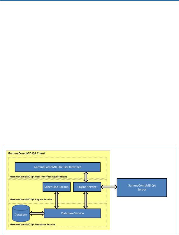
The following drawing shows the structure of the GammaCompMD QA Client software, when installed on a workstation.
Figure 1: GammaCompMD QA Client software structure
GammaCompMD QA Client consists of several Graphical User Interface (GUI) Applications and several System Services running in the background, even when no user is logged in.
Copyright © NEC Display Solutions Ltd., 2006 -2015 |
8 |

GammaCompMD QA Client User Manual
The Applications are called up from a taskbar icon, where a user - depending on user level - checks display status, does calibrations, conformance tests, QA tests or visual tests.
The three most important System Services are:
The QAEngine Service
Communicating with the connected displays and sensors, the Applications, the Database Service and - when connected - with the GammaCompMD QA Server.
The Database Service
Controlling a local database system to save all events and results and communicating with the Applications via the QAEngine Service.
The Scheduled Backup Service
Taking care of automated backups of the database contents, when enabled and maintained active schedules. During installation of GammaCompMD QA, a GCMDQABackupUser account is created to manage the background operation of this service.
The communication of these system services with the Applications and the GammaCompMD QA Server is managed using different IP addresses and different TCP Port addresses.
Therefore it is crucial for successful installation and operation of GammaCompMD QA Client that these addresses are not blocked, firewalled or run in conflict with other applications on the workstation. GammaCompMD QA Client is installed with the following IP addresses and TCP Port addresses (numbers) by default:
-System Service (including QAEngine service and Backup service):
-IP: Localhost, TCP Port: 53250
-Database Service:
IP: Localhost, TCP Port: 5432
If required, these TCP Port addresses may be modified later with the 7.7.1.2 Reinitialize System Configuration (page 108) menu.
NOTE: An additional Event Logger system service will be used to communicate with the
GammaCompMD QA Server, using the server’s target IP address and HTTPS protocol with default TCP Port address: 443. This service however is not enabled during Installation. See 7.7.1.2 Reinitialize System Configuration (page 108) to configure the server connection.
Copyright © NEC Display Solutions Ltd., 2006 -2015 |
9 |

GammaCompMD QA Client User Manual
1.System Environment
1.1. Before you start
This manual contains instructions for using GammaCompMD QA Client software. GammaCompMD QA Client is designed to run in the following operating environment. Please check the system environment before installing GammaCompMD QA Client software.
1.2.Operating System Environment
Windows XP professional SP2 or later, 32/64bit (32-bit compatibility mode) Japanese/English/German/French/Spanish/Italian
Windows 7 professional SP1 or later, 32/64bit (32-bit compatibility mode) Japanese/English/German/French/Spanish/Italian
Windows 8 / 8.1 professional , 32/64bit (32-bit compatibility mode) Japanese/English/German/French/Spanish/Italian
An IPv4 / IPv6 based network
1.3.Workstation Hardware
|
CPU |
Minimum: Pentium 4, 1.6 GHz |
|
Recommended: Core2Duo, 2.1 GHz or greater |
|
|
HDD |
300MB+ of free space |
Memory Minimum: 512MB Recommended: 1GB or greater
LAN Minimum: 100 Mbps Recommended: 1000 Mbps or above
1.4.Display Sensors
Front Sensors: MD212MC, MD213MC, MD210C2, MD211C2, MD242C2, MD210C3, MD211C3, MD302C4, MD302C6, MD213MG, MD211G3, MD212G3, MD215MG, MD211G5
Retractable Sensor: MD-N2M5B
1.5.External Sensors
MDSVSENSOR3 by NEC (USB)
i1 Display version 2 by X-Rite (GretagMacbeth) (USB)
Chroma 5 Colorimeter by X-Rite (USB)
i1Display Pro by X-Rite (USB)
ColorMunki by X-Rite (USB)
Copyright © NEC Display Solutions Ltd., 2006 -2015 |
10 |
GammaCompMD QA Client User Manual
i1Pro by X-Rite (USB)
Spyder3 by Colorvision (USB)
Konica Minolta CA-210 (RS-232C/USB)
|
IBA LXplus (RS-232C) |
- Color measurement not supported |
|
Unfors Luxi (RS-232C) |
- Color measurement not supported |
|
IBA LXcan(USB) |
- Color measurement not supported |
IBA LXchroma(USB)
1.6.Pre-requisite Software
Adobe Reader (Version 7.0 or later) – To display the Help file
An internet browser – To read exported QA Test HTML files (i.e. Internet Explorer 7 or later, Firefox 6 or later).
1.7.Supported Display Models
GammaCompMD QA Client supports the following display models
Supported Display Models
NEC MultiSync 90 Series |
LCD1990SXi |
|
|
|
LCD1990SX |
|
|
|
LCD2090UXi |
|
|
|
LCD2190UXi |
|
|
|
LCD2190UXp |
|
|
|
LCD2190UXi |
|
|
|
LCD2490WUXi |
|
|
|
LCD2490WUXi2 |
|
|
|
LCD2690WUXi |
|
|
|
LCD2690WUXi2 |
|
|
|
LCD3090WQXi |
|
|
|
LCD1990SXp |
|
|
NEC MD Series (Grayscale) |
MD21GS-2MP |
|
|
|
MD21GS-3MP |
|
|
|
MD205MG |
|
|
|
MD205MG-1 |
|
|
NEC MD Series (Display Sensor |
MD213MG |
Model / Grayscale) |
|
MD215MG (USB cable required) |
|
|
|
|
MD211G3 |
|
|
|
MD212G3 (USB cable required) |
|
|
|
MD211G5 (USB cable required) |
|
|
Copyright © NEC Display Solutions Ltd., 2006 -2015 |
11 |

|
|
GammaCompMD QA Client User Manual |
|
|
|
|
|
|
|
|
|
|
NEC MD Series (Color) |
MD21M |
|
|
|
|
|
|
|
MD304MC |
|
|
|
|
|
|
|
MD301C4 |
|
|
|
|
|
|
|
MD322C8 |
|
|
|
|
|
|
NEC MD Series (Display Sensor |
MD212MC |
|
|
Model / Color) |
|
|
|
MD213MC |
|
|
|
|
|
|
|
|
MD210C2 |
|
|
|
|
|
|
|
MD211C2 |
|
|
|
|
|
|
|
MD242C2 |
|
|
|
|
|
|
|
MD210C3 |
|
|
|
|
|
|
|
MD211C3 |
|
|
|
|
|
|
|
MD302C4 |
|
|
|
|
|
|
|
MD302C6 (USB cable required) |
|
|
|
|
|
|
NEC EA Series |
EA193Mi |
|
|
|
|
|
|
|
EA224WMi |
|
|
|
|
|
|
|
EA234WMi |
|
|
|
|
|
|
|
EA244WMi |
|
|
|
|
|
|
|
EA244UHD |
|
|
|
|
|
|
|
EA273WMi |
|
|
|
|
|
|
|
EA274WMi |
|
|
|
|
|
|
|
EA275WMi |
|
|
|
|
|
|
|
EA275UHD |
|
|
|
|
|
|
|
EA294WMi |
|
|
|
|
|
|
|
EA304WMi |
|
|
|
|
|
|
|
EA305WMi |
|
|
|
|
|
|
NEC MultiSync PA Series |
PA231W |
|
|
|
|
|
|
|
PA241W |
|
|
|
PA271W |
|
|
|
|
|
|
|
PA301W |
|
|
|
|
|
|
|
PA242W |
|
|
|
|
|
|
|
PA272W |
|
|
|
|
|
|
|
PA302W |
|
|
|
|
|
|
|
PA322UHD |
|
|
|
|
|
|
NEC MultiSync P Series |
P241W |
|
|
|
|
|
|
|
P232W |
|
|
|
|
|
Copyright © NEC Display Solutions Ltd., 2006 -2015 |
12 |
|
|
GammaCompMD QA Client User Manual |
|
|
|
|
|
|
|
|
|
|
|
P242W |
|
|
|
|
|
|
NEC Public Display Series |
X651UHD |
|
|
(For displaying medical images) |
|
|
|
X841UHD |
|
|
|
|
|
|
|
|
X981UHD |
|
|
|
|
|
|
NEC large format models |
Multeos M40 |
|
|
|
|
|
|
|
Multeos M46 |
|
|
Note: |
|
|
|
Multeos LCD M401 |
|
|
|
Gamma correction only, manual |
|
|
|
Multeos LCD M461 |
|
|
|
adjustment of luminance is |
|
|
|
LCD 4020 |
|
|
|
required |
|
|
|
LCD 4620 |
|
|
|
|
|
|
|
|
LCD 5220 |
|
|
|
|
|
|
|
LCD 6520L |
|
|
|
|
|
|
|
LCD 6520P |
|
|
|
|
|
|
|
LCD X461UN |
|
|
|
|
|
|
|
LCD X461HB |
|
|
|
|
|
|
|
LCD P401 |
|
|
|
|
|
|
|
LCD P461 |
|
|
|
|
|
|
|
LCD S401 |
|
|
|
|
|
|
|
LCD S461 |
|
|
|
|
|
|
|
LCD S521 |
|
|
|
|
|
|
|
LCD P521 |
|
|
|
|
|
|
|
LCD P402 *Using DVI connection only |
|
|
|
|
|
|
|
LCD P462 *Using DVI connection only |
|
|
|
|
|
Copyright © NEC Display Solutions Ltd., 2006 -2015 |
13 |

GammaCompMD QA Client User Manual
2.Checking System Dependencies
2.1. External Sensors
External sensor drivers are included with the GammaCompMD QA Client. Please install GammaCompMD QA Client before connecting any external sensor to the system. If multiple external sensors are connected simultaneously, they will not be correctly identified. Please connect only one external sensor.
2.2. Attaching MD-N2M5B Sensors and External Sensors
The NEC MD-N2M5B external sensor can be used to perform automated calibrations on some display models. Some MD-N2M5B sensors and external sensors cannot be stopped by the operating system (the [Safely Remove Hardware] icon is not shown in the taskbar). To remove a sensor that does not have this icon, only remove it after checking that the sensor is not in use. It is recommended that the sensor be removed after stopping the GammaCompMD QA Client.
2.3. Updating GammaCompMD QA Client with MD-N2M5B sensor(s)
If updating from GammaCompMD QA Client Version 4.0.10, the settings of MD-N2M5B sensor will be discarded. Set it up again after upgrading. For more information about sensor settings, refer to 7.2.6 Sensor Setup (page 77).
2.4. Using the CA-210 Color Analyzer
If connecting with serial communication, set the baud rate for the sensor unit to 9600bps. The sensor will not be detected if it is set at another baud rate. Settings are not necessary when connecting with USB communications. Also, special modes set at the CA-210 (MEAS or 0-CAL) will not be recognized by GammaCompMD QA Client. Please follow the instructions displayed at the start of calibration and startup to properly set the mode. You cannot use a CA-210 which supports two or more measuring probes. Only one probe connection is supported. Please refer to detailed instructions how to use this instrument in the CA-210 user manual.
2.5. Using the IBA LXplus instrument
For ambient light measurement, the optional lux sensor needs to be attached to the LXplus instrument. Please turn the LXplus power to OFF when attaching / detaching the Lux sensor. At this time, be careful to not pull out the USB cable when performing USB communications with a USB - serial conversion adapter. Please refer to detailed instructions how to use this instrument in the LXplus user manual.
Copyright © NEC Display Solutions Ltd., 2006 -2015 |
14 |

GammaCompMD QA Client User Manual
2.6. Using the IBA LXcan or LXchroma instrument
For ambient light measurement, the optional LxLs lux sensor needs to be attached to the LXcan or LXchroma instrument. Please turn the LXcan or LXchroma power to OFF when attaching / detaching the Lux sensor. Please refer to detailed instructions how to use this instrument in the LXcan or LXchroma user manual.
The screen contact mask is needed for measuring directly on screens.
The distance mode requires a distance of about 50 cm for measuring, an ultrasound range finder is integrated in the LXcan or LXchroma. On the display, the distance is shown as an arrow indicating in which direction the device must be moved to reach the right measurement distance.
2.7. Using the Unfors Luxi (new product name: Raysafe Solo Light) instrument
It is equipped with a light detector which can be used for both measuring display luminance and ambient light. Please turn the sensor's power OFF when enabling / disabling the ambient light detector. Be careful to not pull out the USB cable when performing USB communications with a USB - serial conversion cable.
NOTE: Only Unfors Luxi instruments equipped with firmware version 5.05 or later are supported by GammaCompMD QA Client software. Please refer to detailed instructions in the Unfors Luxi (XI Kit) User Manual.
2.8. Using the Windows Power Management Option
When the power management option is used in Windows XP (or when the Microsoft “Windows PC Automatic Energy-Saving Program” is used), an external sensor may not be recognized after the system returns from standby or sleep mode. If a sensor is not recognized, remove it, reconnect it, and check that the external sensor automatic detection and calibration are working normally.
2.9. Using Displays without PIP Support
With a display model not supporting PIP MODE, GammaCompMD QA Client cannot be used when the display is connected using multiple inputs (e.g. DVI input + DisplayPort input) through cables to one or more workstations. Please make sure that only one input is connected to the display before using GammaCompMD QA Client. Also, please perform a re-initialization of the display configuration when you disconnect/reconnect display cables to change connection.
Copyright © NEC Display Solutions Ltd., 2006 -2015 |
15 |

GammaCompMD QA Client User Manual
2.10. Calibration, Test, Level Measurements, and QA Testing
Do not turn off power, enter the power management manually (from OS side), unplug cables, or remove external sensors’ USB cables during calibration, conformance test, uniformity test, white/black level measurements or QA tests, as doing so will have a negative effect on accuracy. If re-initialization is necessary, follow the instructions in
7.7.1.1Re-initialization of Display Configuration (page 105).
2.11.Lost Password
User passwords must be set by a user with (local) administrator rights. GammaCompMD QA will need to be reinstalled if the Advanced User password is lost.
2.12. Using NEC MD215MG
When using the MD215MG model, some additional action is required to support this model within GammaCompMD QA Client, including connecting a USB cable from the computer to the monitor. Please refer to 13 MD215MG EDID Serial Number Update Tool (page 168).
2.13. Using NEC MD211G5
When using the MD211G5 model, connecting a USB cable from the computer to the monitor is required for communication.
2.14.Using NEC MD302C6
When using the MD302C6 model, connecting a USB cable from the computer to the monitor is required for communication.
When you use external sensor, use a color sensor.
If a signal cable is changed after installation or calibration, please execute re-initialization of the display configuration and execute re-calibration. Regarding how to operate, refer to 7.7.1.1 Re-initialization of Display Configuration (page 105) and 7.2 Calibration (page 54).
If an external sensor was used for the calibration, the actually calibrated luminance will be slightly lower than the selected target luminance.
This effect will happen under the following conditions:
OS: Windows7 or later
Display controller: Display Port 10-bit output is enabled.
Countermeasure: Disable 10-bit support (NVIDIA Quadro Series factory default: Enabled) or keep 10-bit support disabled (AMD Firepro Series factory default: Disabled).
Copyright © NEC Display Solutions Ltd., 2006 -2015 |
16 |

GammaCompMD QA Client User Manual
2.15. Using NEC X651UHD/X841UHD/X981UHD
If GCMDQA has not recognized the NEC model X651UHD, X841UHD and X981UHD, check the following using the ON-SCREEN-DISPLAY (OSD) menu of this large format display
SPECTRAVIEW ENGINE is’ ON’.
DDC/CI is ’ENABLE’.
(Refer to the display's documentation for details.)
2.16. Using NEC MD212G3
When using the MD212G3 model, connecting a USB cable from the computer to the monitor is required for communication.
2.17. Using M-Series Display Controllers from Matrox
When using M-Series display controllers from Matrox while the system is logged off, any scheduled executions will not function. Also, when logging on to Windows after it was once logged off, there may be cases where the displays are not correctly recognized by GammaCompMD QA Client. In this case, please execute re-initialization of the display configuration. Regarding how to operate, refer to 7.7.1.1 Re-initialization of Display Configuration (page 105).
2.18. ECO mode, Auto brightness, and Human sensing function
When using EA Series model, please turn off the above functions manually before the calibration.(Refer to the display's documentation for details.)
When using MD211C3, MD210C3, MD211C2, MD210C2, MD242C2 or MD302C4 models, Human Sensing is turned OFF automatically while each function runs. Human Sensing returns to original setting after each function runs. If a display entered into power saving mode by Human Sensing, a display will return form power saving mode before running each function.
When the calibration will be started, the display will perform a warm-up after having returned from power saving mode.
2.19. Using Windows 8 / 8.1
If you want to upgrade from Windows 7 to Windows 8 / 8.1, and GammaCompMD QA was installed, a seamless operation of GammaCompMD QA cannot be guaranteed. For this case, the following operation is recommended:
(1)Backup data before an upgrade to Windows 8 / 8.1. Refer to 3.6 Database Backup (page 32).
Copyright © NEC Display Solutions Ltd., 2006 -2015 |
17 |
GammaCompMD QA Client User Manual
(2)Uninstall GammaCompMD QA.
(3)Upgrade to Windows 8 / 8.1.
(4)Re-Install GammaCompMD QA.
(5)Restore Backup data. Refer to 7.7.1.2 Reinitialize System Configuration (page 108).
If restoring backup data (history) is not desired, only perform step (2), (3) and (4).
GammaCompMD QA Client performs as Desktop Application.
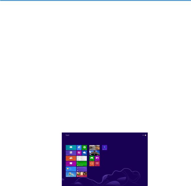
If Start Screen (Figure 2) and/or Modern UI Application (Windows Store apps) are shows, the execution of network and/or schedule tests are suspended. You need to close the Start Screen or Windows Store apps. When the Desktop is shown, the execution of network and/or schedule tests starts.
While the schedule test and/or the execution of network performs, a Main Screen can’t be started. If you need to operate a Main Screen, complete, cancel or postpone the execution of network and/or the schedule test before operating a Main Screen.
Figure 2: Start Screen of Windows 8 / 8.1
Do not change to the Start Screen and Windows Store apps during execution of GammaCompMD QA Client.
Do not show the charm bar during execution of GammaCompMD QA Client.
Launch GammaCompMD QA Client after canceling a snap view.
LXcan and LXchroma are not supported on Windows8.1.
When using MD215MG, MD211G5, MD212G3 or MD302C6 on Windows8.1, it may cause GammaCompMD QA Client to malfunction. In this case, disable [USB Selective Suspend] in Windows 8 / 8.1.
2.20. Common Dialog Box Conventions
GammaCompMD QA Client displays separate dialog boxes for each of its features. The following describes the function of buttons and checkboxes in the dialog boxes.
Copyright © NEC Display Solutions Ltd., 2006 -2015 |
18 |

GammaCompMD QA Client User Manual
Dialog boxes with only an OK button
Clicking OK closes the dialog box. When displaying a dialog box with display selection buttons again, the previous selections are cleared. Make the selections again.
Dialog boxes with OK and Cancel buttons
Clicking OK performs the intended action (enables setting / start calibration / view report). Clicking Cancel closes dialog box without applying any changes.
Dialog boxes with OK, Cancel, and Apply buttons
Clicking OK enables settings and closes the dialog box. Clicking Cancel cancels any change and closes the dialog box. However, the settings that were applied by clicking the Apply button will not be changed back. Clicking Apply applies settings but does not close the dialog box.
Dialog boxes with OK and View buttons
Clicking OK closes the dialog box. Clicking View will cause all changes to be lost in dialog boxes with checkboxes. Clicking View will show the test pattern.
Checkboxes
Select All/Deselect All Checkboxes
Checking these will check all available items in dialog box.
Un-checking this will deselect all available items in the dialog box.
NOTE: When the checkbox is in a tab such as in 7.7.1.5 Alert Setup (page 116), it affects only those checkboxes in the currently selected tab.
Windows Commands, Menus and Messages
All instructions and menu references related to the Windows operating system are shown within brackets.
Example: Select the [General] tab on the [Windows Firewall] screen.
2.21. Using PIP Enabled Displays
PIP MODE supported display models are able to display information from more than one input on one screen at the same time. Please refer to the display’s user manual for details.
GammaCompMD QA Client can handle configurations where two or more inputs are
Copyright © NEC Display Solutions Ltd., 2006 -2015 |
19 |

GammaCompMD QA Client User Manual
displayed on one screen. Set up the input sequence, screen order in Windows and the display area according to the example settings shown on the next page.
Copyright © NEC Display Solutions Ltd., 2006 -2015 |
20 |

GammaCompMD QA Client User Manual
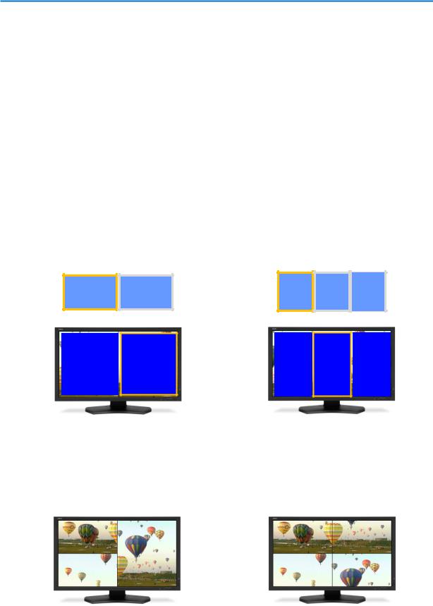
Examples for correct setup
Screen order in Windows setting view and actual display screen should be the same.
Screen setting in Windows Screen setting in Windows
|
1 |
|
2 |
|
|
2 |
|
1 |
|
|
|
|
|
|
|
|
|
|
|
|
Screen setting on display |
|
|
|
|
|
|
||
|
|
|
|
|
|
|
|
|
|
|
1 |
|
2 |
|
2 |
|
1 |
|
|
|
|
|
|
|
|
|
|
|
|
(a) Correct example 1 |
(b) Correct example 2 |
Screen setting in Windows |
Screen setting in Windows |
1 |
2 |
3 |
2 |
1 |
|
3 |
|||||
|
|
|
|
||
Screen setting on display |
Screen setting on display |
||||
1 |
2 |
3 |
2 |
1 |
|
3 |
|||||
|
|
|
|
||
(c) Correct example 3 |
(d) Correct example 4 |
||||
Screen setting in Windows |
Screen setting in Windows |
||||
|
1 |
|
|
|
|
|
|
|
|
|
|
|
3 |
|
|
|
1 |
|
2 |
|
|
|
|
|
|
|
|
|
|
|
|
|
|
2 |
|
|
|
|
|
|
|
||
|
|
3 |
|
4 |
|
|||||
|
|
|
|
|
|
|
|
|||
Screen setting on display |
|
|
|
|
|
|||||
Screen setting on display |
||||||||||
|
|
|
|
|
|
|
|
|
|
|
1 |
|
3 |
|
|
1 |
|
2 |
|
||
|
|
|
|
|
|
|
|
|
|
|
2 |
|
|
|
|
|
|||||
3 |
|
4 |
|
|||||||
|
|
|
|
|
|
|||||
|
|
|
|
|
|
|
|
|
|
|
|
(e) Correct example 5 |
(f) Correct example 6 |
||||||||
Figure 3: Examples of correct display settings when using PIP MODE
Copyright © NEC Display Solutions Ltd., 2006 -2015 |
21 |
GammaCompMD QA Client User Manual
When you perform a calibration, luminance measurement or QA test, PIP MODE will be turned off automatically. You can test the correct input, using the following:
1.Manually turn “PIP MODE” OFF on the display via control button.
2.For case (a), (c), (e) and (f), you should only see the image of display area #1, otherwise changes in connection sequence are required. For case (b) and (d), change some settings to see the image of display area #2 image as well.
3.Turn ON “PIP MODE (PbP) (hereinafter referred to as PbP)” and reconfirm the screen order.
4.Refer to the display's documentation for PIP MODE. The identification of the display within Windows can be changed by settings of the screen resolution. Perform procedure 1 to 3 if you changed settings.
Examples of incorrect setup (I.e. changing the settings via the OSD’s SWAP function)
Screen order in Windows setting view and actual display screen are mismatched.
Screen setting in Windows
1 2
Screen setting on display
Screen setting in Windows
1 |
2 |
3 |
Screen setting on display
2 |
1 |
2 |
1 |
3 |
(a) Incorrect example 1 |
(b) Incorrect example 2 |
|||
Screen setting in Windows |
Screen setting in Windows |
|||
|
|
|
|
|
|
|
|
1 |
|
2 |
|
|
1 |
|
|
3 |
|
|
|
|
|
||
|
|
|
|
|
|
|
|
|
|
|
|
|
2 |
|
|
|
3 |
|
4 |
|
|||
|
|
|
|
|
|
|
|
|
|||
|
|
|
|
|
|
|
|
|
|
|
|
Screen setting on display |
Screen setting on display |
||||||||||
|
|
|
|
|
|
|
|
|
|
|
|
2 |
|
|
3 |
|
|
3 |
|
4 |
|
||
|
|
|
|
|
|
|
|
|
|
|
|
1 |
|
1 |
|
2 |
|
||||||
|
|
|
|
|
|
|
|||||
(d) Incorrect example 3 |
(f) Incorrect example 4 |
||||||||||
Figure 4: Example of incorrect display setting when using PIP MODE
Copyright © NEC Display Solutions Ltd., 2006 -2015 |
22 |
GammaCompMD QA Client User Manual
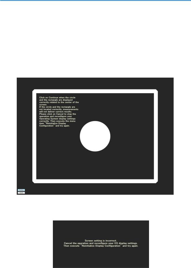
If the main screen setting is correctly done, Sensor Contact Position Guide (Figure 57) will be shown before calibration or taking other measurements starts. If QA Test starts, the following message (Figure 5) will be shown before calibration or taking other measurements starts.
When the circle and the rectangle are displayed correctly related to the center of screen, the user is allowed to continue the operation.
If the circle and the rectangle are displayed incorrectly, click the cancel button. In this case, execute 7.7.1.1 Re-initialization of Display Configuration (page 105) after setting according to the correct example.
Figure 5: Continue Operation dialog
When the main screen setting is not correctly done, the following message (Figure 6) may be shown. In this case, please check and redo the setting.
Figure 6: Abort Operation dialog
Copyright © NEC Display Solutions Ltd., 2006 -2015 |
23 |

GammaCompMD QA Client User Manual
IMPORTANT NOTES:
Unlike other sensors, retractable sensor executes calibration automatically when connected to the system. As long as PIP MODE main screen setting is correctly done, calibration will be completed properly without showing Sensor Contact Position Guide (Figure 57) or Continue Operation dialog (Figure 5). If the screen is not correctly set, calibration will stop with an error message. Please set up PIP MODE correctly again and re-execute the calibration.
If the buttons of the Sensor Contact Position Guide (Figure 57) or Continue Operation dialog (Figure 5) are not shown, push the ESC key to cancel the operation.
When displaying two or more inputs on one screen, it is necessary that both inputs are connected to the same display controller. Displays cannot be managed properly when each input is connected to a different display controller.
When displaying two or more inputs on one screen, please connect the signal cables of same connector type (Display Port/DVI/HDMI) to the display.
Any change of Windows display settings or display controller or input or connection of a different display typically requires an update of configuration settings. In such a case, please execute “Re-initialization of the Display Configuration” in GammaCompMD QA Client.
Executing QA Test with PIP MODE equipped displays will always show Continue Operation dialog (Figure 5) regardless of PIP MODE setting (ON/OFF). If the screen configuration is correct, press “Continue” to continue your operation.
If using this function on a display with PIP MODE (PbP), you need to input the appropriate resolution on the screen to perform correctly the visual test. When you change the resolution manually, please return to the original settings after the visual test.
When the display sensor (Front sensor model or Retractable sensor) is used, be sure to set the both the EXPANSION mode and the PIP MODE to “FULL” in the ON-SCREEN-DISPLAY (OSD) of the display.
Please set the PIP MODE not to "Picture in Picture" but to "Picture by Picture".
Copyright © NEC Display Solutions Ltd., 2006 -2015 |
24 |

GammaCompMD QA Client User Manual
If the operation with the PIP MODE (PbP) goes wrong, connect the PC with the display using an USB cable. This is an alternative way of communication between PC and Display.
Refer to the display's documentation for details.
If the restoration of PIP MODE (PbP) from OFF to ON takes unusually long time, connect the PC with the display using an USB cable. Refer to the display's documentation for details.
After the calibration, the BLACK LEVEL value may return to the value before the calibration when PIP MODE (PbP) is set to OFF or ON. In this case, please set the value of BLACK LEVEL to 50.0% by the OSD menu.
In MD302C6, when two inputs of INPUT1+INPUT2 will be displayed, both inputs should use the same type of connector, and set up to the same resolution. Set up coordinates according to correct example.
If the calibration with the PIP MODE(PbP) goes wrong, execute 7.7.1.1 Re-initialization Display Configuration after setting PIP MODE to OFF. Execute calibration again after re-initialization.
When displaying two or more inputs on one screen, please unify Picture Mode setting, Luminance setting, Contrast setting, and Black level setting via the ON-SCREEN-DISPLAY (OSD) menu.
Refer to the display's documentation for details.
When an upgrade installation was done while PIP MODE (PbP) has been in ON state, please execute 7.7.1.1 Re-initialization of Display Configuration (page 105).
Copyright © NEC Display Solutions Ltd., 2006 -2015 |
25 |

GammaCompMD QA Client User Manual
3.Installation
Administrator privileges are required in order to install this software. If the user does not have administrator rights, a prompt will appear requesting an administrator’s username and password. Follow the on-screen instructions to continue with the installation.
Selecting Only for me in Select Options dialog box (Figure 8) will set the input ID as the current user and a desktop shortcut will be created for the [Administrator] account. Selecting the Anyone who uses this computer (all users) option will allow also [Standard User] accounts to run GammaCompMD QA Client.
External sensor drivers are included in the GammaCompMD QA Client package as described in 1.5 External Sensors (page 10). Install GammaCompMD QA Client before connecting sensors to the computer. GammaCompMD QA Client can be installed by double clicking setup.exe from your GammaCompMD QA Client installation media or download package.
NOTE:
GammaCompMD QA Version 5 cannot be installed on a system which has GammaCompMD Version 2, GammaCompMD QA Version 3, or SpectraView II installed as well. The installation will stop, notifying the user of the conflicting software.
Un-install these applications, as required.
You may re-install GammaCompMD QA Version 3 or SpectraView II to use them after GammaCompMD QA Client Version 5 has been installed.
Please do not use GammaCompMD QA Client Version 5, GammaCompMD QA Client Version 3 and SpectraView II concurrently, because connected displays may not be set up correctly, as these programs work with the same access method to control the displays, resulting in access conflicts.
Copyright © NEC Display Solutions Ltd., 2006 -2015 |
26 |
GammaCompMD QA Client User Manual
3.1. Setup
NOTE: If GammaCompMD Version 2 or GammaCompMD QA Version 3 Client is still installed on the system, these need to be un-installed manually before this setup.
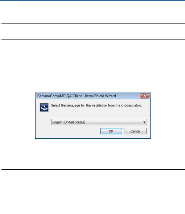
When installation begins, a Choose Setup Language (Figure 7) and then an Options Selection (Figure 8) dialog box will be displayed. Follow the instructions accordingly for any other dialog boxes that may appear. In addition, a Readme file is shown. After reading the contents, click on the x to exit.
Language Selection
Figure 7: Choose Setup Language dialog box
Select your language for the installation from the Choose Setup Language dialog box.
NOTE:
If you select Japanese during installation in other than Japanese version of Windows XP, you need to insert “East Asian languages” in advance. Please set up “East Asian Languages” from the “Region and Language” in “Control Panel” before the installation.
If you perform an upgrade, it will be executed in the same language which you selected during first installation.
Copyright © NEC Display Solutions Ltd., 2006 -2015 |
27 |
GammaCompMD QA Client User Manual
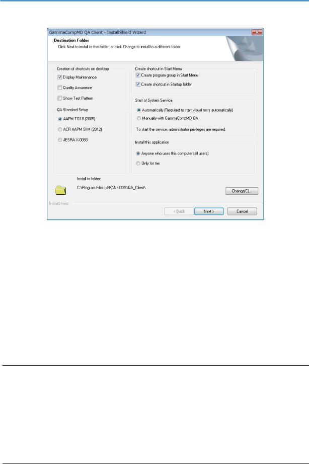
Options Selection
Figure 8: Options Selection dialog box
This box is available to select the following installation options.
Creation of desktop shortcuts
Display Maintenance / Quality Assurance / Show Test Pattern)
QA Standard Setup
(AAPM TG18 / ACR AAPM SIIM / JESRA X-0093)
Create shortcut in Start Menu
(Start Menu / Startup Menu)
Start of System Service
(Automatically / Manually)
NOTE: System Service refers to installed Windows System Services. These system services access the database, control the display and communicate with a GammaCompMD QA Server.
If Automatically is selected, these services are started at boot up time of the system and run permanently in the background, even if no user is logged in.
If Manually with GammaCompMDQA is selected, these services must be manually started, using the following steps: Open Display Maintenance menu, then enter:
System Setup Reinitialize System Configuration
Copyright © NEC Display Solutions Ltd., 2006 -2015 |
28 |
GammaCompMD QA Client User Manual
Install this application
(Anyone who uses this computer (all users) / Only for me)
Install to folder:
By default, GammaCompMD QA will be installed in the following folder:
Windows 32-bit versions |
C:\[Program Files]\NECDS\QA_Client |
Windows 64-bit versions |
C:\[Program Files(x86)]\NECDS\QA_Client |
NOTE: In the following, this user manual refers to these folders as [Installation Folder].
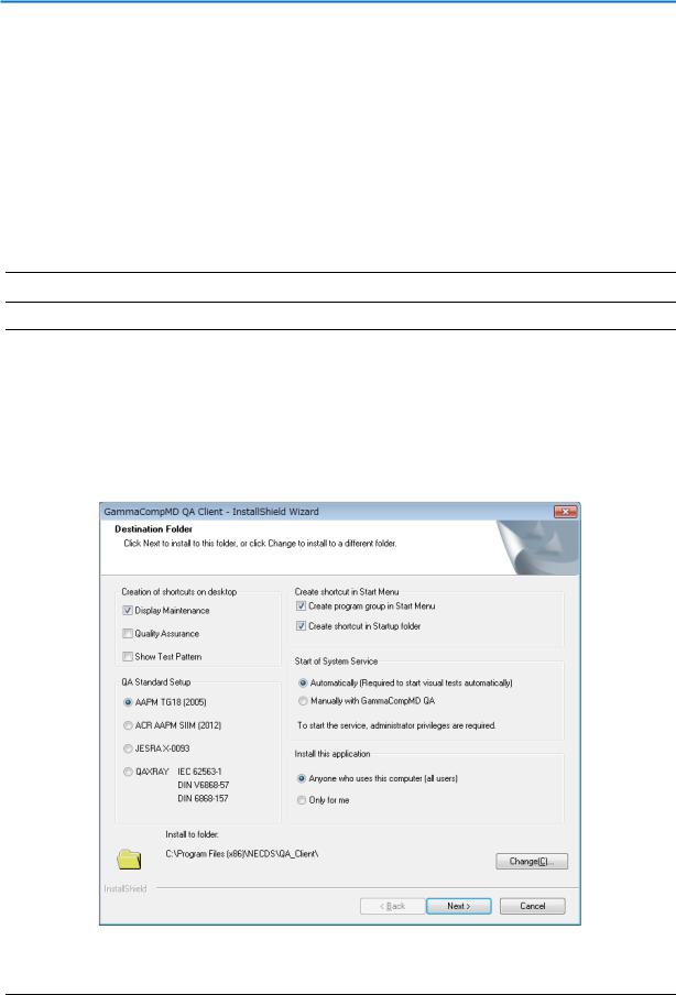
EU Limited Edition:
If you are using GammaCompMD QA Client for EU, you can select QAXRAY (IEC 62563-1/DIN V 6868-57/DIN 6868-157) at the time of installation. (Figure 9). When you select QAXRAY, the installation dialog box for QAXRAY will be displayed during the installation. Install QAXRAY according to the message of the dialog box. Please note: If the installation of QAXRAY is canceled, the installation of GammaCompMD QA Client will be canceled as well.
Figure 9:Options Selection dialog box (EU Limited Edition)
Copyright © NEC Display Solutions Ltd., 2006 -2015 |
29 |
GammaCompMD QA Client User Manual
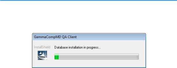
3.2. Installation of the internal database
During the installation process, GammaCompMD QA also installs a PostgreSQL database, as shown in Figure 10.
Figure 10: Database installation in progress…
This database is used to save all calibration actions, measurement data, QA tests and alerts and to build a history of the status of the connected display over time.
In addition, the database is used for providing actual and historical data, when the Client communicates with a GammaCompMD QA Server in a networked environment.
In case that a problem occurs during database installation or initialization, a message pops up with an error code. Below find a small list of error codes and a short description related to the installation/initialization of the GammaCompMD QA Client internal database during installation.
Error Code |
Description |
|
|
8 |
Database connection error |
|
|
13 |
Cancelled by another process |
|
|
26 |
Database initialization error |
|
|
33 |
Exceptional error in database |
|
|
GammaCompMD QA Client assumes that the user installing this application has full (local) administration rights.
The database communicates with the main application and with other system services via IP address (127.0.0.1; localhost) and TCP port number: 5432.
To find the cause of an installation failure, please check (among other possible causes):
Are there any limitations to the local administrator rights, or is an automatic creation of an account blocked, i.e. via Microsoft’s advanced group policy management?
Any TCP port conflicts with other applications, or any firewall port blocking?
Does the system run another PostgreSQL or other database installation?
Copyright © NEC Display Solutions Ltd., 2006 -2015 |
30 |
 Loading...