


 Loading...
NEC Express Server
Express5800 Series
Express5800/R120d-2M
EXP292
User’s Guide
Model Number: N8100-1793F
Chapter 1 General Description
Chapter 2 Preparations
Chapter 3 Setup
Chapter 4 Appendix
10.021.02-101.01
April 2012, First Edition © NEC Corporation 2012

Documents Provided with This Product
Documents Provided with This Product
Documents for this product are provided as accompanying booklets (  ) and as electronic manuals ( PDF ) stored within EXPRESSBUILDER DVD (
 ).
).
|
Precautions for Use |
|
Describes points of caution to ensure the safe use of this server. |
|
|
|
|
|
|||
|
|
|
|
Read these cautions before using this server. |
|
|
Getting Started |
|
Describes how to use this server, from unpacking to operations. |
|
|
|
|
|
|
Refer to this guide as you begin for an overview of this server. |
|
|
|
|
|
|
|
|
|
|
|
|
|
|
|
|
|
|
|
|
EXPRESSBUILDER |
|
|
|
|
|
|
|
|
|
|
|
|
|
|
|
|
User’s Guide
Chapter 1: General Description |
Overviews, names, and functions of the server’s parts |
Chapter 2: Preparations |
Installation of additional options, connection of peripheral devices, |
|
and ideal location for this server |
Chapter 3: Setting Up Your Server |
System BIOS configurations and summary of EXPRESSBUILDER |
Chapter 4: Appendix |
Specifications and other information |
|
|
Installation Guide (Windows)
Chapter 1: Installing Windows |
Installation of Windows and drivers, and important information for |
|
installation |
Chapter 2: Installing the Bundled |
Installation of bundled software, such as NEC ESMPRO and |
Software |
Universal RAID Utility |
|
|
Maintenance Guide
Chapter 1: Maintenance |
Server maintenance and troubleshooting |
Chapter 2: Convenient Features |
Useful features and the detail of system BIOS settings, RAID |
|
Configuration Utility, and EXPRESSBUILDER |
Chapter 3: Appendix |
Error messages and Windows Event Logs |
|
|
Other documents
Provides the detail of NEC ESMPRO, Universal RAID Utility, and the other features.
2 |
Express5800/R120d-2M User’s Guide |

Contents
Contents
Documents Provided with This Product................................................................................................................. |
|
|
|
|
2 |
|||
Contents ................................................................................................................................................................ |
|
|
|
|
|
|
3 |
|
Notations Used in This Document ......................................................................................................................... |
|
|
|
|
6 |
|||
|
Notations used in the text.............................................................................................................................. |
|
|
|
|
6 |
||
|
Optical disk drives......................................................................................................................................... |
|
|
|
|
6 |
||
|
Hard disk drives ............................................................................................................................................ |
|
|
|
|
6 |
||
|
Removable media ......................................................................................................................................... |
|
|
|
|
6 |
||
|
Abbreviations of Operating Systems (Windows) |
........................................................................................... |
|
7 |
||||
Trademarks |
........................................................................................................................................................... |
|
|
|
|
|
8 |
|
Regulatory Notices ................................................................................................................................................ |
|
|
|
|
|
9 |
||
Warnings and Additions to This Document .......................................................................................................... |
|
|
|
10 |
||||
|
Latest editions............................................................................................................................................. |
|
|
|
|
|
10 |
|
Precautions for Use (Be Sure to Read) ............................................................................................................... |
|
|
|
|
11 |
|||
|
Safety precautions ...................................................................................................................................... |
|
|
|
|
11 |
||
|
Symbols used in this document and on warning ...............................................................................labels |
|
12 |
|||||
|
Safety notes ................................................................................................................................................ |
|
|
|
|
|
13 |
|
|
|
General 13 |
|
|
|
|
|
|
|
|
Rack installation............................................................................................................................... |
|
|
|
|
14 |
|
|
|
Power supply and power cord use................................................................................................... |
|
|
|
15 |
||
|
|
Installation, relocation, storage, and connection .............................................................................. |
16 |
|||||
|
|
Cleaning and working with internal devices ..................................................................................... |
|
17 |
||||
|
|
During operation .............................................................................................................................. |
|
|
|
|
18 |
|
|
Warning labels ............................................................................................................................................ |
|
|
|
|
|
19 |
|
|
|
External view ................................................................................................................................... |
|
|
|
|
19 |
|
|
Handling precautions (for proper operations).............................................................................................. |
|
|
20 |
||||
General Description............................................................................................................................................. |
|
|
|
|
|
22 |
||
1. |
Introduction ................................................................................................................................................. |
|
|
|
|
|
23 |
|
2. |
Accessories................................................................................................................................................. |
|
|
|
|
|
24 |
|
3. |
Standard Features....................................................................................................................................... |
|
|
|
|
25 |
||
|
3.1 |
Management Features..................................................................................................................... |
|
|
|
|
28 |
|
|
3.2 Firmware and Software Version Management ................................................................................. |
|
29 |
|||||
4. Names and Functions of Parts.................................................................................................................... |
|
|
|
|
30 |
|||
|
4.1 |
Front View........................................................................................................................................ |
|
|
|
|
30 |
|
|
4.2 Front View (without Front Bezel)...................................................................................................... |
|
|
|
31 |
|||
|
4.3 |
Rear View ........................................................................................................................................ |
|
|
|
|
32 |
|
|
4.4 |
External View................................................................................................................................... |
|
|
|
|
33 |
|
|
4.5 |
Internal View .................................................................................................................................... |
|
|
|
|
34 |
|
|
4.6 |
Motherboard .................................................................................................................................... |
|
|
|
|
35 |
|
|
4.7 |
Status Indicators .............................................................................................................................. |
|
|
|
|
37 |
|
|
|
4.7.1 |
POWER LED ( |
) .......................................................................................................... |
|
|
|
37 |
|
|
4.7.2 |
STATUS LED ( )............................................................................................................. |
|
|
|
|
38 |
|
|
4.7.3 |
LINK/ACT LED ( |
1, |
2, ........................................................................... |
3, |
4) |
39 |
|
|
4.7.4 |
DISK Access LED ( |
).................................................................................................... |
|
|
|
39 |
|
|
4.7.5 |
Optical Disk Access LED ................................................................................................... |
|
|
|
39 |
|
|
|
4.7.6 |
UID LED (ID)...................................................................................................................... |
|
|
|
|
39 |
Express5800/R120d-2M User’s Guide |
3 |
|
|
|
Contents |
|
|
|
|
|
4.7.7 |
LED on a hard disk drive ................................................................................................... |
40 |
|
4.7.8 |
LEDs for LAN connectors .................................................................................................. |
41 |
|
4.7.9 |
AC POWER LED on Power Unit........................................................................................ |
42 |
Preparations ........................................................................................................................................................ |
|
43 |
|
1. Installing Internal Optional Devices ............................................................................................................. |
44 |
||
1.1 |
Safety Precautions........................................................................................................................... |
44 |
|
1.2 |
Anti-static Measures ........................................................................................................................ |
45 |
|
1.3 |
Overview of Installation and Removal.............................................................................................. |
46 |
|
1.4 |
Confirming Servers (UID Switch) ..................................................................................................... |
48 |
|
1.5 |
Removing Front Bezel ..................................................................................................................... |
49 |
|
1.6 |
Removing Top Cover ....................................................................................................................... |
50 |
|
1.7 |
Removing PCI Riser Card................................................................................................................ |
51 |
|
1.8 |
Removing Support Bar .................................................................................................................... |
52 |
|
1.9 |
Removing Air Duct ........................................................................................................................... |
53 |
|
1.10 |
Internal Flash Memory (N8115-07) .................................................................................................. |
54 |
|
|
1.10.1 |
Installation.......................................................................................................................... |
54 |
|
1.10.2 |
Removal ............................................................................................................................ |
54 |
1.11 |
TPM Kit ............................................................................................................................................ |
|
55 |
|
1.11.1 |
Installation.......................................................................................................................... |
55 |
1.12 |
Processor......................................................................................................................................... |
56 |
|
|
1.12.1 |
Installation.......................................................................................................................... |
56 |
|
1.12.2 |
Replacement / Removal .................................................................................................... |
60 |
1.13 |
DIMM ............................................................................................................................................... |
|
61 |
|
1.13.1 |
Maximum supported memory size ..................................................................................... |
61 |
|
1.13.2 |
Memory Clock.................................................................................................................... |
62 |
|
1.13.3 |
Memory RAS Feature ........................................................................................................ |
64 |
|
1.13.4 |
DIMM installation order...................................................................................................... |
65 |
|
1.13.5 |
Installation.......................................................................................................................... |
66 |
|
1.13.6 |
Replacement / Removal .................................................................................................... |
67 |
|
1.13.7 |
Using Memory RAS Feature.............................................................................................. |
68 |
1.14 |
Battery for RAID Controller .............................................................................................................. |
76 |
|
|
1.14.1 |
Handling precautions ......................................................................................................... |
76 |
|
1.14.2 |
Installing Battery ................................................................................................................ |
76 |
|
1.14.3 |
Removal ............................................................................................................................ |
77 |
1.15 |
LAN Riser Card................................................................................................................................ |
78 |
|
|
1.15.1 |
Installation.......................................................................................................................... |
78 |
|
1.15.2 |
Removal ............................................................................................................................ |
79 |
1.16 |
Redundant Fan Unit......................................................................................................................... |
80 |
|
|
1.16.1 |
Installation.......................................................................................................................... |
81 |
|
1.16.2 |
Replacement / Removal .................................................................................................... |
82 |
1.17 |
PCI Card.......................................................................................................................................... |
83 |
|
|
1.17.1 |
Notes ................................................................................................................................. |
83 |
|
1.17.2 |
Supported boards and available slots................................................................................ |
84 |
|
1.17.3 |
Installation.......................................................................................................................... |
91 |
|
1.17.4 |
Removal ............................................................................................................................ |
92 |
|
1.17.5 |
Installing RAID Controller................................................................................................... |
93 |
1.18 |
Additional HDD Cage....................................................................................................................... |
95 |
|
|
1.18.1 |
Installation.......................................................................................................................... |
95 |
|
1.18.2 |
Removal ............................................................................................................................ |
97 |
1.19 |
Optical Disk Drive ............................................................................................................................ |
98 |
|
|
1.19.1 |
Installation.......................................................................................................................... |
98 |
|
1.19.2 |
Removal ............................................................................................................................ |
99 |
1.20 |
Use of Internal hard disk drives in the RAID System ..................................................................... |
100 |
|
|
1.20.1 |
Connecting cables ........................................................................................................... |
101 |
|
1.20.2 |
Notes on Building RAID System ...................................................................................... |
103 |
1.21 |
Installing Air Duct ........................................................................................................................... |
104 |
|
1.22 |
Installing Support Bar..................................................................................................................... |
104 |
|
1.23 |
Installing PCI Riser Card................................................................................................................ |
104 |
|
1.24 |
Installing Top Cover ....................................................................................................................... |
104 |
|
1.25 |
Hard Disk Drive.............................................................................................................................. |
105 |
|
|
1.25.1 |
Installation........................................................................................................................ |
105 |
|
1.25.2 |
Removal .......................................................................................................................... |
107 |
|
1.25.3 |
Replacing a hard disk drive in the RAID System ............................................................. |
107 |
4 |
|
Express5800/R120d-2M User’s Guide |
|
|
|
|
|
Contents |
|
|
|
|
|
|
1.26 |
Power Supply Unit ......................................................................................................................... |
108 |
|
|
|
1.26.1 |
Cold Redundant Feature ................................................................................................. |
108 |
|
|
1.26.2 |
Installation........................................................................................................................ |
109 |
|
|
1.26.3 Replacing a Failing Power Supply Unit............................................................................ |
110 |
|
|
1.27 |
Installing the Front Bezel ............................................................................................................... |
111 |
|
2. |
Installation and Connection....................................................................................................................... |
112 |
||
|
2.1 |
Installation...................................................................................................................................... |
112 |
|
|
|
2.1.1 |
Installing Rack ................................................................................................................. |
112 |
|
|
2.1.2 Installing the server to the rack or removing it from the rack............................................ |
114 |
|
|
2.2 |
Connection..................................................................................................................................... |
120 |
|
|
|
2.2.1 Connecting to a uninterruptible power supply (UPS) ....................................................... |
122 |
|
Setup ................................................................................................................................................................. |
|
|
123 |
|
1. |
Turning on the Server ............................................................................................................................... |
124 |
||
|
1.1 |
POST............................................................................................................................................. |
|
125 |
|
|
1.1.1 |
POST sequence .............................................................................................................. |
125 |
|
|
1.1.2 |
POST error messages ..................................................................................................... |
126 |
2. |
System BIOS Setup .................................................................................................................................. |
127 |
||
|
2.1 |
Overview........................................................................................................................................ |
127 |
|
|
2.2 |
Starting and Exiting SETUP Utility ................................................................................................. |
127 |
|
|
|
2.2.1 |
Starting SETUP................................................................................................................ |
127 |
|
|
2.2.2 |
Exiting SETUP................................................................................................................. |
127 |
|
2.3 |
Description on On-Screen Items and Key Usage .......................................................................... |
128 |
|
|
2.4 |
Cases that Require Configuration.................................................................................................. |
130 |
|
3. |
EXPRESSSCOPE ENGINE 3................................................................................................................... |
132 |
||
|
3.1 |
Overview........................................................................................................................................ |
132 |
|
|
3.2 |
EXPRESSSCOPE ENGINE 3 Network configuration .................................................................... |
132 |
|
4. |
EXPRESSBUILDER.................................................................................................................................. |
134 |
||
|
4.1 |
Features of EXPRESSBUILDER ................................................................................................... |
134 |
|
|
4.2 |
Starting EXPRESSBUILDER ......................................................................................................... |
134 |
|
5. |
Installing Software Components................................................................................................................ |
135 |
||
6. |
Turning Off the Server............................................................................................................................... |
136 |
||
Appendix ........................................................................................................................................................... |
|
|
137 |
|
1. |
Specifications ............................................................................................................................................ |
|
138 |
|
2. |
Interrupt Lines ........................................................................................................................................... |
|
140 |
|
Express5800/R120d-2M User’s Guide |
5 |

Notations Used in This Document
Notations Used in This Document
Notations used in the text
In addition to safety-related symbols urging caution, 3 other types of notations are used in this document. These notations have the following meanings.
Important |
Indicates critical items that must be followed when handling the server or operating software. If |
|
the procedures described are not followed, server failure, data loss, and other serious |
|
malfunctions could occur. |
Note |
Indicates items that must be confirmed when handling the server or operating software. |
|
|
Tips |
Indicates information that is helpful to keep in mind when using this server. |
|
|
Optical disk drives
This server is equipped with one of the following drives, depending on the order at the time of purchase. These drives are referred to as optical disk drives in this document.
•DVD-ROM drive
•DVD Super MULTI drive
Hard disk drives
Unless otherwise stated, hard disk drives (HDD) described in this document refer to both of the following.
•Hard disk drives (HDD)
•Solid state drive (SSD)
Removable media
Unless otherwise stated, removable media described in this document refer to both of the following.
•USB memory
•Flash FDD
6 |
Express5800/R120d-2M User’s Guide |

Notations Used in This Document
Abbreviations of Operating Systems (Windows)
Windows Operating Systems are referred to as follows.
Refer to Chapter 1 (1.2 Supported Windows OS) in Installation Guide (Windows) for detailed information.
Notations in this document |
|
Official names of Windows |
|
Windows Server 2008 R2 |
|
Windows Server 2008 R2 Standard |
|
|
Windows Server 2008 R2 Enterprise |
||
|
|
||
Windows Server 2008 |
*1 |
Windows Server 2008 Standard |
|
Windows Server 2008 Enterprise |
|||
|
|
||
Windows Server 2003 R2 x64 Edition |
|
Windows Server 2003 R2 Standard x64 Edition |
|
|
Windows Server 2003 R2 Enterprise x64 Edition |
||
|
|
||
Windows Server 2003 R2 |
*2 |
Windows Server 2003 R2 Standard |
|
Windows Server 2003 R2 Enterprise |
|||
|
|
||
Windows Server 2003 |
*2 |
Windows Server 2003 Standard |
|
Windows Server 2003 Enterprise |
|||
|
|
||
Windows 7 |
|
Windows 7 Professional 64-bit(x64) Edition |
|
|
Windows 7 Professional 32-bit(x86) Edition |
||
|
|
||
Windows Vista |
|
Windows Vista Business 64-bit(x64) Edition |
|
|
Windows Vista Business 32-bit(x86) Edition |
||
|
|
||
Windows XP |
|
Windows XP Professional x64 Edition |
|
|
Windows XP Professional |
||
|
|
||
Windows PE |
*3 |
Windows Preinstallation Environment |
*1: Includes 64-bit and 32-bit Editions unless otherwise stated. The following appears on EXPRESSBUILDER.
•Windows Server 2008 64-bit Edition: Windows Server 2008 x64
•Windows Server 2008 32-bit Edition: Windows Server 2008 x86
*2: Unless otherwise stated, Windows Server 2003 R2 and Windows Server 2003 are collectively referred to as Windows Server 2003.
*3: Used as an installation platform only.
Express5800/R120d-2M User’s Guide |
7 |

Trademarks
Trademarks
EXPRESSSCOPE is a registered trademark of NEC Corporation.
Microsoft, Windows, Windows Server, Windows Vista, and MS-DOS are registered trademarks or trademarks of Microsoft Corporation in the United States and other countries. Intel, Pentium, and Xeon are registered trademarks of Intel Corporation of the United States. AT is a registered trademark of International Business Machines Corporation of the United States and other countries. Adaptec, its logo, and SCSI Select are registered trademarks or trademarks of Adaptec, Inc. of the United States. LSI and the LSI logo design are trademarks or registered trademarks of LSI Corporation. Adobe, the Adobe logo, and Acrobat are trademarks of Adobe Systems Incorporated. DLT and DLTtape are trademarks of Quantum Corporation of the United States. PCI Express is a trademark of Peripheral Component Interconnect Special Interest Group. Linux is a trademark or registered trademark of Linus Torvalds in Japan and other countries. Red Hat® and Red Hat Enterprise Linux are trademarks or registered trademarks of Red Hat, Inc. in the United States and other countries.
All other product, brand, or trade names used in this publication are the trademarks or registered trademarks of their respective trademark owners.
8 |
Express5800/R120d-2M User’s Guide |
Regulatory Notices
Regulatory Notices
FCC Statement
This equipment has been tested and found to comply with the limits for a Class A digital device, pursuant to Part 15 of the FCC Rules. These limits are designed to provide reasonable protection against harmful interference when the equipment is operated in a commercial environment. This equipment generates, uses, and can radiate radio frequency energy and, if not installed and used in accordance with the instruction manual, may cause harmful interference to radio communications. Operation of this equipment in a residential area is likely to cause harmful interference in which case the user will be required to correct the interference at his own expense.
Industry Canada Class A Emission Compliance Statement
This Class A digital apparatus complies with Canadian ICES-003.
Avis de conformité à la réglementation d'Industrie Canada
Cet appareil numérique de la classe A est conforme à la norme NMB-003 du Canada.
CE / Australia and New Zealand Statement
This is a Class A product. In domestic environment this product may cause radio interference in which case the user may be required to take adequate measures (EN55022).
BSMI Statement
Turkish RoHS information relevant for Turkish market
EEE Yönetmeliğine Uygundur.
Disposing of your used product
In the European Union
EU-wide legislation as implemented in each Member State requires that used electrical and electronic products carrying the mark (left) must be disposed of separately from normal household waste. This includes Information and Communication Technology (ICT) equipment or electrical accessories, such as cables or DVDs.
When disposing of used products, you should comply with applicable legislation or agreements you may have. The mark on the electrical and electronic products only applies to the current European Union Member States.
Outside the European Union
If you wish to dispose of used electrical and electronic products outside the European Union, please contact your local authority and ask for the correct method of disposal.
Express5800/R120d-2M User’s Guide |
9 |

Warnings and Additions to This Document
Warnings and Additions to This Document
1.Unauthorized reproduction of the contents of this document, in part or in its entirety, is prohibited.
2.The contents of this document may change without prior notice.
3.Do not make copies or alter the document content without permission from NEC Corporation.
4.Every effort has been made to ensure the completeness of this document. However, if you have any concerns, or discover errors or omissions, please contact your retailer.
5.Regardless of these 4 items, NEC Corporation does not take responsibility for effects resulting from operations.
6.The sample values used in this document are not the actual values.
Keep this document nearby so that you may refer to it as necessary.
Latest editions
This document was created based on the information available at the time of its creation. The screen images, messages and procedures may differ from the actual screens, messages and procedures. Substitute as appropriate when content has been modified.
The most recent version of User’s Guide, as well as other related documents, is also available for download from the following website.
http://www.nec.com/
10 |
Express5800/R120d-2M User’s Guide |
Precautions for Use (Be Sure to Read)
 Precautions for Use (Be Sure to Read)
The following provides information required to use your server safely and properly. For details of names in this section, refer to Names and Functions of Parts in this document.
Safety precautions
Follow the instructions in this document for the safe use of NEC Express server.
This User’s Guide describes hazardous parts of the server, possible hazards, and how to avoid them. Server components with possible danger are indicated with a warning label placed on or around them (or, in some cases, by printing the warnings on the server).
In User’s Guide or on warning labels, WARNING or CAUTION is used to indicate a degree of danger. These terms are defined as follows:

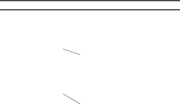
 WARNING

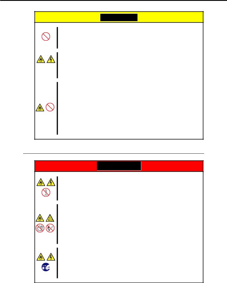
 CAUTION
Indicates there is a risk of death or serious personal injury
Indicates there is a risk of burns, other personal injury, or property damage
Precautions and notices against hazards are presented with one of the following three symbols. The individual symbols are defined as follows:
|
Attention |
This symbol indicates the presence of a hazard if |
(Example) |
|
|
the instruction is ignored. |
|
|
|
An image in the symbol illustrates the hazard type. |
(Electric shock risk) |
|
|
|
|
|
|
|
|
|
Prohibited |
This symbol indicates prohibited actions. An image |
(Example) |
|
Action |
in the symbol illustrates a particular prohibited |
|
|
|
action. |
|
|
|
|
(Do not disassemble) |
|
|
|
|
|
Mandatory |
This symbol indicates mandatory actions. An |
(Example) |
|
Action |
image in the symbol illustrates a mandatory action |
|
|
|
to avoid a particular hazard. |
|
|
|
|
(Disconnect a plug) |
|
|
|
|
Express5800/R120d-2M User’s Guide |
11 |
Precautions for Use (Be Sure to Read)
(A label example used in this User’s Guide)
Symbol to draw |
|
Description of a warning |
|
Term indicating a degree of danger |
attention |
|
|
|
|
|
|
|
|

 WARNING
Use only the specified outlet
Use a grounded outlet with the specified voltage. Use of an improper power source may cause a fire or a power leak.
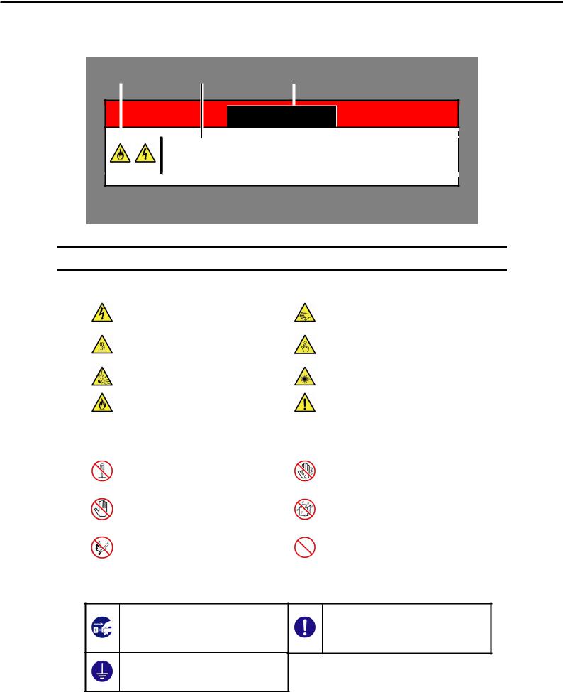
Symbols used in this document and on warning labels
Attentions
|
Indicates the presence of electric shock |
|
Indicates the presence of mechanical |
|
|
hazards. |
|
parts that can result in bodily injury. |
|
|
Indicates the presence of a hot surface |
|
Indicates the presence of mechanical |
|
|
or component. Touching this surface |
|
parts that can result in pinching or other |
|
|
could result in bodily injury. |
|
bodily injury. |
|
|
Indicates there is a risk of explosion. |
|
Indicates the presence of |
laser beam |
|
|
that cause blindness. |
|
|
|
|
|
|
|
|
Indicates there is a risk of fire or fumes. |
|
Indicates a general notice |
or warning |
|
|
that cannot be specifically identified. |
||
|
|
|
||
Prohibited Actions |
|
|
|
|
|
|
|
|
|
|
Do not disassemble, repair, or modify |
|
Do not touch the server with wet hand. |
|
|
the server. Otherwise, an electric shock |
|
Otherwise, an electric shock may be |
|
|
or fire may be caused. |
|
caused. |
|
|
Do not touch the component specified |
|
Do not use the server in the place where |
|
|
by this symbol. Otherwise, an electric |
|
water or liquid may pour. Otherwise, an |
|
|
shock or burn may be caused. |
|
electric shock or fire may be caused. |
|
|
Do not place the server near the fire. |
|
Indicates a general prohibited action |
|
|
Otherwise, a fire may be caused. |
|
that cannot be specifically identified. |
|
|
|
|
|
|
Mandatory Actions
Unplug the power cord of the server. Otherwise, an electric shock or fire may be caused.
Make sure equipment is properly grounded. Otherwise, an electric shock or fire may be caused.
Indicates a mandatory action that cannot be specifically identified. Make sure to follow the instruction.
12 |
Express5800/R120d-2M User’s Guide |

Precautions for Use (Be Sure to Read)
Safety notes
This section provides notes on using the server safely. Read this section carefully to ensure proper and safe use of the server. For symbols, refer to Safety precautions.
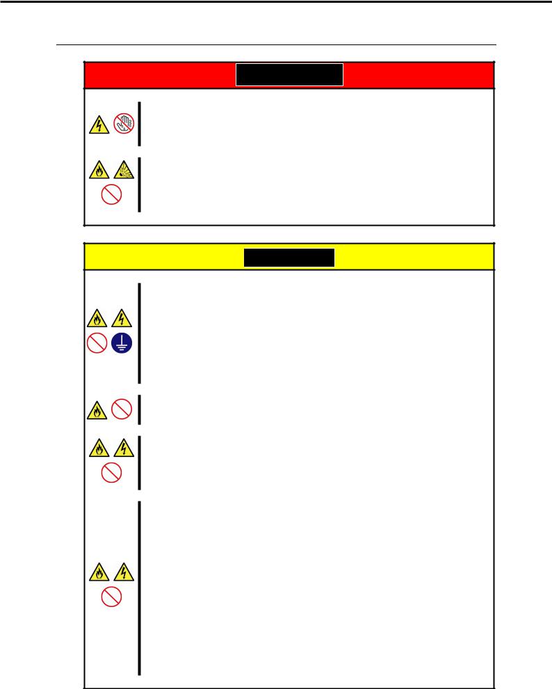
General

 WARNING
Do not use the server for services where human life may be at stake or high reliability is required.
This server is not intended for use in medical, nuclear, aerospace, mass transit or other applications where human life may be at stake or high reliability is required, nor is it intended for use in controlling such applications. We disclaim liability for any personal injury and property damages caused by such use of this server.
Do not use the server if any smoke, odor, or noise is present.
If smoke, odor, or noise is present, immediately turn off the server and disconnect the power plug from the outlet, then contact the store where you purchased the product or your maintenance service company. Using the server in such conditions may cause a fire.
Do not insert needles or metal objects.
Do not insert needles or metal objects into ventilation holes in the server or openings in the optical disk drive. Doing so may cause an electric shock.
Use a rack that conforms to the designated standard
This server can be mounted onto a 19-inch rack that conforms to EIA standards. Do not mount the server onto any rack that does not conform to EIA standards. Doing so may cause a server malfunction, personal injury, or damage to peripheral devices. For more information about racks that can be used with the server, consult with your maintenance service company.
Use the server only under the specified environment
Do not install the server rack in any environment that is not suitable for installation.
Installation in an unsuitable environment is harmful for the server and other systems installed in the rack and may cause fire or personal injury due to the rack falling. For a detailed explanation on installation environments or seismic reinforcement, consult with the instruction manual supplied with the rack or your maintenance service company.

 CAUTION
Keep water or foreign matter away from the server.
Do not let any liquid such as water or foreign materials including pins or paper clips enter the server. Failure to follow this warning may cause an electric shock, a fire, or failure of the server. When such things accidentally enter the server, immediately turn off the power and disconnect the power plug from the outlet. Do not disassemble the server, and contact the store where you purchased the product or your maintenance service company.
Express5800/R120d-2M User’s Guide |
13 |

Precautions for Use (Be Sure to Read)
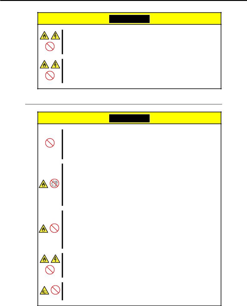
Rack installation

 CAUTION
Do not attempt to carry or install the server alone
More than two people are required to carry or install the rack. Otherwise, the rack may fall, resulting in personal injury or damage to peripheral devices. In particular, tall racks such as a 44U rack become unstable unless steadied with a stabilizer. Make sure that two or more people hold the rack to carry or install the rack.
Do not install with the load weight distributed unevenly
To avoid unevenly distributing the load of the rack and server, install a stabilizer or connect multiple racks to distribute the weight. Otherwise, the rack may fall, resulting in personal injury.
Do not install components alone, and check the door hinge pins of the rack
Two or more people are required to install the rack components such as the door or rails. When installing the door, make sure that both upper and lower hinge pins are held in place. Incomplete attachment may cause components to fall off as well as personal injury.
Do not extend any device from the rack that is not stabilized
When extending a device from the rack, make sure that the rack is stable (by using a stabilizer or seismic reinforcement). Otherwise, the rack may fall, resulting in personal injury.
Do not extend more than one device out of the rack
Extending multiple devices from the rack may cause the rack to fall, resulting in personal injury. Extend only one device at one time.
Do not exceed the rated capacity of the power supply when connecting devices
To prevent burn injuries, fire, and damage to the server, make sure the load on the branch circuit that supplies power to the rack will not exceed the rated load. For inquiries regarding the installation or wiring of the power supply system, consult with the company that performed the installation or wiring, or the power company that services your area.
14 |
Express5800/R120d-2M User’s Guide |
Precautions for Use (Be Sure to Read)
Power supply and power cord use
 WARNING
Do not hold the power plug with a wet hand.
Do not disconnect/connect the plug while your hands are wet. Failure to follow this warning may cause an electric shock.
Do not connect the ground wire to a gas pipe.
Never connect the ground wire to a gas pipe. Failure to follow this warning may cause a gas explosion.

 CAUTION
Plug in to a proper power source.
Use a grounded outlet with the specified voltage. Use of an outlet with a voltage other than that specified causes fire and electrical leakage. Do not install the server in any environment that requires an extension cord. Connecting to a cord that does not conform to the power supply specs of the server causes overheating, resulting in fire.
If you want to use an AC cord set with a ground wire of class 0I, be sure to connect the ground wire before inserting the power plug into the outlet. Before disconnecting the ground wire, be sure to disconnect the power plug from the output.
Do not connect many cords into a single outlet by using extension cords.
The electric current exceeding the rated flow overheats the outlet, which may cause a fire.
Insert the power plug into the outlet as far as it goes.
Heat generation resulting from a halfway inserted power plug (imperfect contact) may cause a fire. Heat will also be generated if condensation is formed on dusty blades of the halfway inserted plug, increasing the possibility of fire.
Do not use any unauthorized interface cable.
Use only the interface cables provided with the server. Electric current that exceeds the amount allowed could cause fire. Also, observe the following precautions to prevent electrical shock or fire caused by a damaged power cord.
•Do not stretch the cord harness
•Do not bend the power cord.
•Do not twist the power cord
•Do not step on the power cord.
•Uncoil the power cord before use
•Do not secure the power cord with staples or equivalents
•Do not pinch the power cord
•Keep chemicals away from the power cord
•Do not place any object on the power cord
•Do not alter, modify, or repair the power cord
•Do not use a damaged power cord (replace the damaged power cord with a power cord of the same standard. For information on replacing the power cord, contact the store where you purchased the product or a maintenance service company)
Express5800/R120d-2M User’s Guide |
15 |
Precautions for Use (Be Sure to Read)

 CAUTION
Do not use the attached power cord for any other devices or usage.
The power cord that comes with your server is designed aiming to connect with this server and to use with the server, and its safety has been tested. Do not use the attached power cord for any other purpose. Doing so may cause a fire or an electric shock.
Do not pull out a cable by gripping the cable part.
Pull a cable straight out by gripping the connector part. Pulling a cable by gripping the cable part or applying extra pressure to the connector part may damage the cable part, which may cause a fire or electric shock.
Installation, relocation, storage, and connection

 CAUTION
Do not attempt to lift the server by yourself
Some servers weigh up to 31 kg depending on the server components. Carrying the server by yourself may damage your back. At least two people should securely hold the server from the bottom when carrying it. Do not attempt to lift the server while the front bezel attached. Doing so causes the front bezel to fall off the server, resulting in personal injury.
Do not install the server in any place other than specified.
Do not install the server in the following places or any place other than specified in this User's Guide.
Failure to follow this instruction may cause a fire.
• A dusty place
•A humid place such as near a boiler
•A place exposed to direct sunlight
•An unstable place
Do not use the server in an environment where corrosive gas is present
Do not install the server in a place subject to corrosive gases including sodium chloride, sulfur dioxide, hydrogen sulfide, nitrogen dioxide, chlorine, ammonia, or ozone. Do not install the server in an environment that contains dust, chemicals that accelerate corrosion such as NaCl or sulfur, or conductive materials. Failure to follow this warning may cause the wiring on the printed wiring board to short-circuit, leading to fire. If you have any questions, contact the store where you purchased the product or a maintenance service company.
Do not install the server while the cover is removed
Do not install the server to a rack while the cover or other relevant items removed. Not only will the cooling effect within the server decrease, causing the server to malfunction, but also may allow dust to enter the server, resulting in fire or electrical shock.
Do not get your fingers caught in the rails
When mounting/removing the server onto/from the rack, be careful to avoid getting your fingers caught in the rails or cutting your fingers on the rails.
16 |
Express5800/R120d-2M User’s Guide |
Precautions for Use (Be Sure to Read)

 CAUTION
Do not apply any weight on the server when it is extended from the rack
Do not apply force on the server when it is extended from the rack. Doing so cause the frames to bend, which makes it impossible to be mounted on the rack. It also may cause the server to fall, resulting in personal injury.
Do not attempt to connect or disconnect the interface cable while the power cord is plugged into an outlet
Be sure to unplug the power cord from a power outlet before connecting/disconnecting any interface cable to/from the server. If the server is off-powered but its power cord is plugged to a power source, touching a cable or connector may cause an electric shock or a fire resulted from a short circuit.
Use only the specified interface cable.
Use only interface cables provided by NEC and locate a proper device and connector before connecting a cable. Using an authorized cable or connecting a cable to an improper destination may cause a short circuit, resulting in a fire.
Also, observe the following notes on using and connecting an interface cable.
•Do not use any damaged cable connector.
•Do not step on the cable.
•Do not place any object on the cable.
•Do not use the server with loose cable connections. Do not use any damaged cable.
Cleaning and working with internal devices

 WARNING
Do not disassemble, repair, or alter the server.
Never attempt to disassemble, repair, or alter the server on any occasion except as described in this document. Failure to follow this warning may cause not only malfunction of the server but also an electric shock or fire.
Do not attempt to remove lithium, NiMH, or Li-ion batteries.
The server contains the lithium, NiMH, or Li-ion battery (some optional devices have a lithium, NiMH, or Li-ion battery installed). Do not remove the battery. Placing a battery close to a fire or in the water may cause an explosion.
When the server does not operate appropriately due to the dead battery, contact the store you purchased the product or your maintenance service company. Do not attempt to disassemble the server to replace or recharge the battery by yourself.
Disconnect the power plug before cleaning the server.
Be to power off the server and disconnect the power plug from a power outlet before cleaning or installing/removing internal optional devices. Touching any internal device of the server with its power cord connected to a power source may cause an electric shock even of the server is off-powered.
Occasionally disconnect the power plug from the outlet and clean the plug with a dry cloth. Heat will be generated if condensation is formed on a dusty plug, which may cause a fire.
Express5800/R120d-2M User’s Guide |
17 |

Precautions for Use (Be Sure to Read)

 CAUTION
High temperature
Components including internal hard disk drives in the server are extremely hot just after the server is turned off. Allow the surface to cool before installing/removing.
Secure cables or cards in place
Be sure to secure the power cord, interface cables, and cards in place. Incomplete installation causes a loose connection, resulting in smoke or fire
Electric shock
The cooling fans, hard disk drives, and power supply unit (only when two servers are installed) support hot swapping. If replacing a component when the electrical current is being supplied, use extreme caution not to get electric shock by touching terminal parts of the internal components.
During operation

 CAUTION
Do not pull out or remove the server from the rack.
Do not pull the server out of the rack or remove it from the rack. In addition to causing equipment to not function properly, separating the server from the rack may result in personal injury.
Avoid contact with the server during thunderstorms.
Do not touch any part of the server including the cables when a thunderstorm is approaching. Also, do not connect or disconnect any devices. There may be a risk of electric shock from lightning strike.
Keep animals away from the server.
Keep animals such as pets away from the server. Pet hair or other waste enters the server, which may cause a fire or electric shock.
Do not leave the optical disk drive tray open.
Dust may get in the server when the tray is open, which may result in a malfunction. In addition, bumping the open tray could cause personal injury.
Do not remove the server from the rack while it is operating.
Do not pull out or remove the server from the rack while the server is running. In addition to causing equipment to not function properly, separating the server from the rack may result in personal injury.
Do not place any object on top of servers.
Separating the server from the rack may result in personal injury and damage to nearby personal belongings.
Do not get yourself caught in the fan
Keep your hands and hair away from the cooling fan at the rear of the server during operation. Failure to observe this warning may cause your hands or hair to catch in the fan, resulting in personal injury.
18 |
Express5800/R120d-2M User’s Guide |

Precautions for Use (Be Sure to Read)
Warning labels
Warning label are attached on or near the components with potential hazards (This label is either attached or printed on the component.) to draw attention from users to potential hazards involved in handling the server. (Do not remove or black out this label and keep it clean). If no label is attached or printed on the server, or if there is a label coming off or stained, contact your sales representative .
External view
Express5800/R120d-2M User’s Guide |
19 |

Precautions for Use (Be Sure to Read)
Handling precautions (for proper operations)
Be sure to observe the following precautions for the proper functioning of the server. Ignoring the precautions may cause server malfunction or failure.
• Do not use any cell phone or PHS and switch off them near the server. Electric waves from such devices can cause server to malfunction.
• Install the server in an appropriate place. For details about the installation location, refer to Chapter
2 Preparations (2. Installation and Connection).
• Before connecting/removing cables to/from peripheral devices, make sure that the server is off and unplug the power cord, if they are non plug-and-play devices.
• Connect the provided power cord to a 100/200 VAC outlet.
• Make sure that the access LED on the server is off before turning off the power or ejecting an optical disk.
• Wait for at least 30 seconds before turning on the server after turning off the server.
• If any Uninterruptible Power Supply unit is connected, set it to wait for at least 30 seconds before turning on the server after power off.
• Do not press the POWER switch to turn on the server before the POWER LED (amber) is unlit.
• Turn off the server and unplug the power cord before moving it.
• Regularly clean the server to prevent various types of failure. (Refer to Chapter 1 Maintenance (2.
Daily Maintenance) in "Maintenance Guide" for details about cleaning.)
• Momentary voltage drop may occur due to lightning strike. To prevent this, use of UPS is recommended.
• We do not guarantee that any copy-protected CD that does not conform to standards will play on the server’s optical disk drive.
• In the following cases, check and adjust the system clock before operation.
− After transportation − After storage
− After the server is used following a period of disuse, in which storage conditions did not conform to those that guarantee server operations (temperature: see the table below; humidity: 20% to 80%).
N code |
|
|
|
N8101- |
|
|
|
||
545F |
546F |
547F |
548F |
549F |
550F |
551F |
552F |
||
|
|||||||||
|
|
|
|
|
|
|
|
|
|
Operation guarantee |
|
10 to 40°C |
|
10 to |
|
10 to 40°C |
|
10 to |
|
temperature |
|
|
35°C |
|
|
35°C |
|||
|
|
|
|
|
|
||||
• Check the system clock approximately once per month. Use of a time server (NTP server) is
recommended if high accuracy timing is required by the system.
• In order to get the server and internal devices to work properly, we recommend you store the server at room temperature.
Observe the storage conditions (Temperature: −10°C to 55°C, Humidity: 20% to 80%, No condensation of moisture) to store the server.
• Do not power off or reset the server, nor disconnect the power cord before POST completes.
• If this server, internal optional devices, and media set for the backup devices (tape cartridges) are moved from a cold place to a warm place in a short time, condensation will occur and cause malfunctions and failures when these are used in such state. To protect important stored data and property, make sure to wait for a sufficient period to use the server and components in the operating environment.
Reference: Time effective at avoiding condensation in winter (more than 10°C differences between the room temperature and atmospheric temperature)
Disk devices: Approximately 2 to 3 hours |
Tape media: Approximately 1 day |
•For optional devices, we recommend you use our NEC products. Even if they are successfully installed or connected, installation of unsupported devices can cause the server to malfunction or even failure. You will be charged to repair failure or damage caused by use of such products even within warranty period.
20 |
Express5800/R120d-2M User’s Guide |
Precautions for Use (Be Sure to Read)
Tips for your health and safety
Using a computer extensively may affect different parts of your body. Here are tips you should follow while working on a computer to minimize strain on your body.
Keep proper posture
The basic body position for using a computer is sitting straight with your hands on the keyboard parallel with the floor, and your eyes directed slightly downward toward the monitor. With the proper posture described above, no unnecessary strain is applied on any part of your body, in other words when your muscles are most relaxed.
Working on the computer with bad posture such as hunching over or being too close to the monitor could cause fatigue or deteriorated eyesight.
Adjust the angle of your display
Most display units are designed for adjustment of the horizontal and vertical angles. This adjustment is important to prevent the screen from reflecting bright lights and to make the display contents easy to see. Working without adjusting the display to a comfortable angle makes it difficult for you to maintain a proper posture and you will get tired easily. Adjust the viewing angle before use.
Adjust the brightness and contrast of the display
Display screens have functions to control brightness and contrast. The most suitable brightness/contrast depends on age, individuals, and environment, so adjust it to suit your preferences. A too bright or too dark display is bad for your eyes.
Adjust the angle of keyboard
Some keyboards are ergonomically designed, which allow the angle to be adjusted. Adjusting the angle of the keyboard is effective to reduce tension on your shoulders, arms, and fingers.
Clean your equipment
Keeping your equipment clean is important not only for the appearance but also for functional and safety reasons. A dusty monitor makes it difficult to see the display contents, so clean it regularly.
Take rest breaks
When you feel tired, take a break. Light exercise is also recommended.
Express5800/R120d-2M User’s Guide |
21 |
|
NEC Express5800 Series |
1 |
|
|
|
|
|
|
Express5800/R120d-2M |
|
|
|
|
|
|
|
|
|
|
|
General Description |
||
This chapter introduces the features of this server and the name of each part.
1.Introduction
2.Accessories
Verify the condition of your server's accessories.
3.Standard Features
This section describes the server’s features and the server management.
4.Names and Functions of Parts
This section describes the name of each part contained in this server.
22 |
Express5800/R120d-2M User’s Guide |

Chapter 1 General Description |
1. Introduction |
|
|
1. Introduction
Thank you for purchasing this NEC Express5800 Series product.
This high performance server is powered by the latest microprocessor "Intel® Xeon® processor".
NEC’s latest technology and architectures realize high-power and high-speed operation that cannot be matched by existing servers.
The server is designed with consideration of not only reliability but also expandability, which enables you to use it as a network server.
Read this document before using the server thoroughly to fully understand handling of Express5800 Series Server and appreciate its functions to the maximum extent.
Express5800/R120d-2M User’s Guide |
23 |

Chapter 1 General Description |
2. Accessories |
|
|
2. Accessories
The carton box contains various accessories which are required for setup or maintenance. Make sure you have them all for future use.
•Slide Rails
•EXPRESSBUILDER*1
•SAS/SATA cable (when RAID controller is unmounted)
•Getting Started
•Fixing screw for internal backup device (x4)
*1 Documents are stored in EXPRESSBUILDER. Adobe Reader is required to read the documents so make sure you have it installed in your PC.
Make sure you have all accessories and inspect them. If an accessory is missing or damaged, contact your sales representative.
Important The chassis serial number plate and maintenance label is located on the server. If the serial number does not match the number on the warranty, you may not be guaranteed against failure even within the warranty period. Contact your sales representative if they do not match.
24 |
Express5800/R120d-2M User’s Guide |

Chapter 1 General Description |
3. Standard Features |
|
|
3. Standard Features
The server has the following standard features:
High performance
•Intel® Xeon® processor
–N8101-545F: E5-2609 (2.40GHz 4 Core)
–N8101-546F: E5-2630L (2.00GHz 6 Core)
–N8101-547F: E5-2640 (2.50GHz 6 Core)
–N8101-548F: E5-2643 (3.30GHz 4 Core)
–N8101-549F: E5-2650 (2.00GHz 8 Core)
–N8101-550F: E5-2650L (1.80GHz 8 Core)
–N8101-551F: E5-2670 (2.60GHz 8 Core)
–N8101-552F: E5-2690 (2.90GHz 8 Core)
•Turbo Boost Technology feature
•Hyper Threading Technology feature *1
•High-speed memory access (DDR3L 1600 supported)*2
•High-speed disk access (SATA/SAS 6Gbps supported)
•High-speed 1000BASE-T/100BASE-TX/10BASE-T (2 ports) interface (1Gbps/100Mbps/10Mbps supported)
High reliability
•Processor throttle-ring feature
•Memory monitoring feature (error correction/error detection)
•Memory degeneracy feature (logical isolation of a failed device)
•Memory x4 SDDC feature
•Memory mirroring, memory LockStep (x8 SDDC), memory sparing features
•Memory throttle-ring feature
•Bus parity error detection
•Temperature detection
•Error detection
•Internal fan monitoring feature
•Internal voltage monitoring feature
•RAID System (Disk Array) (An option card is required.)
•Auto rebuild feature (hot swapping supported)
•BIOS password feature
•The security lock that comes with Front Bezel
•Redundant fan system
Express5800/R120d-2M User’s Guide |
25 |
Chapter 1 General Description |
3. Standard Features |
|
|
Management Utilities
•NEC ESMPRO
•ExpressUpdate
•Remote controlling feature (EXPRESSSCOPE Engine 3)
•RAID System management utility (Universal RAID Utility)
•Hard disk drive monitoring
•Power supply monitoring
Power saving and noiseless design
•Can select the best power supply unit according to system environment / load / configuration.
•Power monitoring feature
•Power control feature
•80 PLUS® Platinum certified high efficiency power supply
•Fan control appropriate to environment, work load, and configuration
•Silent sound design
•Enhanced Intel SpeedStep® Technology supported
Expandability
•PCI Express 3.0 (x8 lanes): 3 slots (Full Height)
•PCI Express 3.0 (x4 lanes): 2 slots (Low profile)
•PCI Express 3.0 (x8 lanes): 1 slot (dedicated to RAID Controller)
•PCI Express 3.0 (x8 lanes): 1 slot (dedicated to LAN Riser card)
•PCI Express 3.0 (x16 lanes) or PCI-X slot can be configured with optional riser card.
•Large capacity memory of up to 768 GB *3
•Can upgrade to multi-processor system with up to two processors
•Expansion Bay (for hard disk drives): 16 slots *4
•Optical disk drive bay provided as standard
•Expansion bay for backup device provided as standard
•USB2.0 interface (Front: 2 ports, rear: 4 ports, internal: 2 ports)
•Three LAN ports (one for management LAN)
•With optional LAN riser card, two ports can be added.
Ready to use
•No cable connection is required to install a hard disk drive and additional power supply unit, and additional redundant fan (hot swap supported).
26 |
Express5800/R120d-2M User’s Guide |
Chapter 1 General Description |
3. Standard Features |
|
|
Many built-in Features
•Redundant power supply system supported (valid when optional power supply unit is installed)
•El Torito Bootable CD-ROM (no emulation mode) format supported
•Software power-off
•Remote power-on feature
•AC-Link feature
•Remote console feature
•Power switch mask
•Connector for display unit provided on front panel
•Baseboard Management Controller (BMC) conforming to IPMI v2.0
Self-diagnosis
•Power On Self-Test (POST)
•Test and Diagnosis (T&D) utility
Easy setup
•EXPRESSBUILDER (setup utility)
•BIOS Setup utility (SETUP)
Maintenance features
•Off-line Tools
•Memory dump feature using DUMP Switch
•Feature to back up and restore BIOS/BMC settings using EXPRESSSCOPE Profile Key
*1: Unsupported on Xeon® processor E5-2609 embedded models.
*2: Processor core speed depends on processor type, number and type of DIMMs installed, and operating voltage (1.35/1.5 V).
*3: In 2-CPU configuration. Up to 384 GB in 1-CPU configuration
*4: With N8151-39 2.5-inch Hot Plug Drive Cage installed. Eight slots in standard configuration.
Express5800/R120d-2M User’s Guide |
27 |
Chapter 1 General Description |
3. Standard Features |
|
|
3.1 Management Features
The hardware components of the server provide operation control/reliability features as shown below. Additionally, NEC ESMPRO Agent, which is provided in EXPRESSBUILDER, enables you to collectively manage the state of your systems. You can also monitor the server states from a PC to manage the network where NEC ESMPRO Manager provided in EXPRESSBUILDER is installed.
The features available on this server are as shown in the table below.
Function |
Availability |
Description |
|
Hardware |
|
Shows physical hardware information. |
|
|
Memory bank |
|
Shows physical memory information. |
|
Device info |
|
Shows information specific to the server. |
|
CPU |
|
Shows physical CPU information. |
System |
|
Shows logical CPU information and monitors the load factor. |
|
|
|
|
Shows logical memory information and monitors the status. |
I/O device |
|
Shows information on I/O devices (serial ports, keyboard, mouse, and |
|
|
|
|
video). |
System |
|
Monitors temperatures, fans, voltage, power supply, and others. |
|
environment |
|
|
|
|
Temperature |
|
Monitors the temperature inside of the chassis. |
|
|
|
|
|
Fan |
|
Monitors the fans. |
|
|
|
|
|
Voltage |
|
Monitors the voltage inside of the chassis. |
|
|
|
|
|
Power supply |
|
Monitors the power supply unit. |
|
|
|
|
|
Cover / Door |
× |
Monitors Chassis Intrusion (open/close state of chassis cover or door). |
|
|
|
|
Software |
|
Shows service, driver, and OS information. |
|
Network |
|
Shows network (LAN) information and monitors packets. |
|
BIOS |
|
Shows BIOS information. |
|
Local polling |
|
Monitors the values of MIB items obtained by NEC ESMPRO Agent. |
|
Storage |
|
Monitors controllers and storage devices including hard disk drives. |
|
File system |
|
Shows the file system configuration and monitors the free space. |
|
RAID System |
|
Monitors the following RAID Controllers: |
|
|
|
|
• Optional RAID Controller (N8103-149/150/151/160) |
Others* |
|
Monitors OS stall using the Watch Dog Timer. |
|
|
|
|
Performs alert processing after an OS STOP error occurs. |
|
|
|
|
: Supported. : Partially supported. ×: Unsupported. *: Not displayed on the NEC ESMPRO Manager screen.
Tips |
NEC ESMPRO Manager and NEC ESMPRO Agent are supplied with the server as |
|
standard. For how to install and use each software component, refer to the |
|
explanation of the component. |
|
|
28 |
Express5800/R120d-2M User’s Guide |

Chapter 1 General Description |
3. Standard Features |
|
|
3.2 Firmware and Software Version Management
Use of NEC ESMPRO Manager and ExpressUpdate Agent allows you to manage versions of firmware and software as well as update them by applying update packages.
This feature automatically updates modules without stopping the system just by specifying the updating packages from NEC ESMPRO Manager.
Express5800/R120d-2M User’s Guide |
29 |

Chapter 1 General Description |
4. Names and Functions of Parts |
|
|
4. Names and Functions of Parts
This section describes the names of the server parts.
4.1 Front View
(3)-1 (3)-3 |
(4) |
(6) |
(7) |
|
|
|
|
|
|
|
|
|
|
|
|
|
|
|
|
|
|
|
|
|
|
|
|
|
|
|
|
|
|
|
|
|
|
|
|
|
|
|
|
|
|
|
|
|
|
|
|
|
|
|
|
|
|
|
|
|
|
|
|
|
|
|
|
|
|
|
|
(3)-2 |
(3)-4 |
(5) |
(1) |
|
(2) |
(1)Front Bezel
The cover to protect the front of the server. This cover can be locked with the provided Bezel Lock Key.
(2)Key Slot
(5)STATUS LED
This LED indicates the server status. (See page 38.)
(6)Unit ID (UID) LED
The slot for Bezel Lock Key that is used to lock Front Bezel.
This LED turns on when UID Switch is pressed. Commands from the software also cause it to turn on or flash. (See page 39.)
(3) LINK/ACT LED |
(7) POWER LED |
This LED turns on when the server is connected to the network.
(3)-1: LAN connector 1
(3)-2: LAN connector 2
(3)-3: LAN connector 3
(3)-4: LAN connector 4
LEDs for LAN3 and LAN4 are lit when optional LAN riser card is installed. (See page 39.)
This LED indicates power status of server.(See page 37.)
(4)Disk Access LED
This LED indicates status of internal hard disk drive. (See page 39.)
30 |
Express5800/R120d-2M User’s Guide |
Loading...