


Criterion 60
Table of contents
 Loading...
MTS Criterion
Test System Operation
™
Series 60
100-275-893 A be certain.

©
2014 MTS Systems Corporation. All rights reserved.
Trademark Information
MTS, FlexTest, RPC, and TestWare are registered trademarks and MTS Acumen, MTS TestSuite,
Station Builder, and Station Manager are trademarks of MTS Systems Corporation within the United
States. These trademarks may be protected in other countries. All other trademarks are the property
of their respective holders.
Proprietary Software
Software use and license is governed by MTS’s End User License Agreement which defines all rights
retained by MTS and granted to the End User. All Software is proprietary, confidential, and owned by
MTS Systems Corporation and cannot be copied, reproduced, disassembled, decompiled, reverse
engineered, or distributed without express written consent of MTS.
Software Verification and Validation
MTS software is developed using established quality practices in accordance with the requirements
detailed in the ISO 9001 standards. Because MTS-authored software is delivered in binary format, it
is not user accessible. This software will not change over time. Many releases are written to be
backwards compatible, creating another form of verification. The status and validity of MTS’s operating
software is also checked during system verification and routine calibration of MTS hardware. These
controlled calibration processes compare the final test results after statistical analysis against the
predicted response of the calibration standards. With these established methods, MTS assures its
customers that MTS products meet MTS’s exacting quality standards when initially installed and will
continue to perform as intended over time.
Manual Part Number—Publication Date—Release
100-275-893 A— March 2014 — MTS TestSuite TW 2.3 or later with Insight Controller

Table of Contents
Technical Support
How to Get Technical Support.........................................................................................................................7
Before You Contact MTS.................................................................................................................................7
If You Contact MTS by Phone.........................................................................................................................9
Problem Submittal Form in MTS Manuals....................................................................................................10
Preface
Before You Begin...........................................................................................................................................11
Documentation Conventions..........................................................................................................................11
Safety
Overview........................................................................................................................................................16
Safety Information Overview.............................................................................................................16
Personnel Qualications.................................................................................................................................17
Personnel Qualications.....................................................................................................................17
Hazards...........................................................................................................................................................17
System Hazard Zones.........................................................................................................................17
Hazard Placard Placement..................................................................................................................17
Hazard Warning Icons........................................................................................................................18
Energy Isolation/Lockout/Tagout...................................................................................................................19
Identify Lockout/Tagout Points..........................................................................................................19
Site Precautions..............................................................................................................................................20
Site Precautions..................................................................................................................................20
Guards, Doors, and Covers............................................................................................................................21
Equipment Guards, Doors, and Covers..............................................................................................21
Equipment Weight and Lift Points.................................................................................................................22
Heavy Equipment Hazards.................................................................................................................22
Safety Practices..............................................................................................................................................22
General Safety Practices.....................................................................................................................22
Safety Practices Before Operating the System...................................................................................23
Safety Practices While Operating the System ...................................................................................27
Table of Contents
System Introduction
About This Manual.........................................................................................................................................32
About Other MTS Documentation.................................................................................................................32
System Overview...........................................................................................................................................33
Integrated Operations Platform Overview.....................................................................................................34
Computer Front Panel........................................................................................................................35
3

Table of Contents
Load Frame Overview....................................................................................................................................36
Software Overview.........................................................................................................................................46
Key Concepts
About This Chapter........................................................................................................................................60
Understanding Your MTS Software...............................................................................................................60
Understanding MTS Applications and File Types.........................................................................................61
Understanding the Control Loop....................................................................................................................62
Understanding How Load Frame Components Move....................................................................................64
Understanding How the Grips Move.............................................................................................................66
Tension Test Overview...................................................................................................................................67
Compression Test Overview..........................................................................................................................68
Using the E-Stop Control...............................................................................................................................70
Resolving Error Conditions............................................................................................................................70
Test Table...........................................................................................................................................38
Test Area Guard and Steps (Optional)...............................................................................................38
Hardware Control Panels....................................................................................................................39
Load Unit Control Module.....................................................................................................39
Hydraulic Control Panel.........................................................................................................42
Handset...................................................................................................................................43
Running the Example Tension Test
Overview........................................................................................................................................................74
Safety Orientation..........................................................................................................................................74
Turn On the Station........................................................................................................................................76
Clear Interlocks..............................................................................................................................................78
Recover from a Tripped Limit........................................................................................................................80
Position the Actuator (Upper Crosshead and Table)......................................................................................81
Set Up the Load Meter for Specimen Installation..........................................................................................83
Position the Lower Crosshead........................................................................................................................84
Install the Specimen.......................................................................................................................................86
Optional: Installing an Extensometer.............................................................................................................89
Set Up Meters for the Test..............................................................................................................................94
If Required, Resolve Resource Errors............................................................................................................96
Running the Test.............................................................................................................................................98
Removing the Specimen...............................................................................................................................100
Ready the Load Frame for the Next Test.....................................................................................................103
Analyze the Results......................................................................................................................................104
Reviewing, Analyzing, and Reporting Data
Reviewing Analyzing and Reporting Data...................................................................................................106
4

Analysis Procedure...........................................................................................................................106
Troubleshooting
Troubleshooting............................................................................................................................................130
Maintenance
Routine Maintenance Overview Checklist...................................................................................................134
Decommissioning
Decommissioning Procedure........................................................................................................................138
Table of Contents
5

Table of Contents
6

Technical Support
How to Get Technical Support
Start with your manuals
The manuals supplied by MTS provide most of the information you need to use and maintain your equipment.
If your equipment includes software, look for online help and README files that contain additional product
information.
Technical support methods
MTS provides a full range of support services after your system is installed. If you have any questions
about a system or product, contact Technical Support in one of the following ways.
Web site
Outside the U.S.
For technical support outside the United States, contact your local sales and service office. For a list of
worldwide sales and service locations and contact information, use the Global MTS link at the MTS web
site:
www.mts.com > Global Presence > Choose a Region
www.mts.com > Contact Us (upper-right corner) > In the Subject field, choose
To escalate a problem; Problem Submittal Form
Worldwide: tech.support@mts.comE-mail
Europe: techsupport.europe@mts.com
Worldwide: 1 800 328 2255 - toll free in U.S.; +1 952 937 4000 - outside U.S.Telephone
Europe: +800 81002 222, International toll free in Europe
Before You Contact MTS
MTS can help you more efficiently if you have the following information available when you contact us for
support.
Know your site number and system number
The site number contains your company number and identifies your equipment type (such as material
testing or simulation). The number is typically written on a label on your equipment before the system
leaves MTS. If you do not know your MTS site number, contact your sales engineer.
Example site number: 571167
MTS Criterion™Series 60 | 7

Technical Support
When you have more than one MTS system, the system job number identifies your system. You can find
your job number in your order paperwork.
Example system number: US1.42460
Know information from prior technical assistance
If you have contacted MTS about this problem before, we can recall your file based on the:
• MTS case number
• Name of the person who helped you
Identify the problem
Describe the problem and know the answers to the following questions:
• How long and how often has the problem occurred?
• Can you reproduce the problem?
• Were any hardware or software changes made to the system before the problem started?
• What are the equipment model numbers?
• What is the controller model (if applicable)?
• What is the system configuration?
Know relevant computer information
For a computer problem, have the following information available:
• Manufacturer’s name and model number
• Operating software type and service patch information
• Amount of system memory
• Amount of free space on the hard drive where the application resides
• Current status of hard-drive fragmentation
• Connection status to a corporate network
Know relevant software information
For software application problems, have the following information available:
• The software application’s name, version number, build number, and (if available) software patch
number. This information can typically be found in the About selection in the Help menu.
• The names of other applications on your computer, such as:
— Anti-virus software
— Screen savers
— Keyboard enhancers
— Print spoolers
8 | MTS Criterion™Series 60

Technical Support
— Messaging applications
If You Contact MTS by Phone
A Call Center agent registers your call before connecting you with a technical support specialist. The agent
asks you for your:
• Site number
• Email address
• Name
• Company name
• Company address
• Phone number where you can be reached
If your issue has a case number, please provide that number. A new issue will be assigned a unique case
number.
Identify system type
To enable the Call Center agent to connect you with the most qualified technical support specialist available,
identify your system as one of the following types:
• Electrodynamic material test system
• Electromechanical material test system
• Hydromechanical material test system
• Vehicle test system
• Vehicle component test system
• Aero test system
Be prepared to troubleshoot
Prepare to perform troubleshooting while on the phone:
• Call from a telephone close to the system so that you can implement suggestions made over the phone.
• Have the original operating and application software media available.
• If you are not familiar with all aspects of the equipment operation, have an experienced user nearby to
assist you.
Write down relevant information
In case Technical Support must call you:
• Verify the case number.
MTS Criterion™Series 60 | 9

Technical Support
• Record the name of the person who helped you.
• Write down any specific instructions.
After you call
MTS logs and tracks all calls to ensure that you receive assistance for your problem or request. If you
have questions about the status of your problem or have additional information to report, please contact
Technical Support again and provide your original case number.
Problem Submittal Form in MTS Manuals
Use the Problem Submittal Form to communicate problems with your software, hardware, manuals, or
service that are not resolved to your satisfaction through the technical support process. The form includes
check boxes that allow you to indicate the urgency of your problem and your expectation of an acceptable
response time. We guarantee a timely response—your feedback is important to us.
You can access the Problem Submittal Form at www.mts.com > Contact Us (upper-right corner) > In the
Subject field, choose To escalate a problem; Problem Submittal Form
10 | MTS Criterion™Series 60

Preface
Before You Begin
Safety first!
Before you use your MTS product or system, read and understand the safety information provided with
your system. Improper installation, operation, or maintenance can result in hazardous conditions that can
cause severe personal injury or death, or damage to your equipment and specimen. Again, read and
understand the safety information provided with your system before you continue. It is very important that
you remain aware of hazards that apply to your system.
Other MTS manuals
In addition to this manual, you may receive additional manuals in paper or electronic form.
You may also receive an MTS System Documentation CD. It contains an electronic copy of the manuals
that pertain to your test system.
Controller and application software manuals are typically included on the software CD distribution disc(s).
Documentation Conventions
The following paragraphs describe some of the conventions that are used in your MTS manuals.
Hazard conventions
Hazard notices may be embedded in this manual. These notices contain safety information that is specific
to the activity to be performed. Hazard notices immediately precede the step or procedure that may lead
to an associated hazard. Read all hazard notices carefully and follow all directions and recommendations.
Three different levels of hazard notices may appear in your manuals. Following are examples of all three
levels. (for general safety information, see the safety information provided with your system.)
Danger:
Danger notices indicate the presence of a hazard with a high level of risk which, if ignored,
will result in death, severe personal injury, or substantial property damage.
MTS Criterion™Series 60 | 11
Preface
Warning:
Warning notices indicate the presence of a hazard with a medium level of risk which, if ignored,
can result in death, severe personal injury, or substantial property damage.
Caution:
Caution notices indicate the presence of a hazard with a low level of risk which, if ignored,
could cause moderate or minor personal injury or equipment damage, or could endanger test
integrity.
Other special text conventions
Important:
Important notices provide information about your system that is essential to its proper
function. While not safety-related, if the important information is ignored, test results may
not be reliable, or your system may not operate properly.
Note:
Notes provide additional information about operating your system or highlight easily
overlooked information.
Recommended:
Recommended notes provide a suggested way to accomplish a task based on what MTS
has found to be most effective.
Tip:
Tips provide helpful information or a hint about how to most efficiently accomplish a task.
Access:
Access provides the route you should follow to a referenced item in the software.
Examples show specific scenarios relating to your product and appear with a shaded
background.
Special terms
The first occurrence of special terms is shown in italics.
Illustrations
Illustrations appear in this manual to clarify text. They are examples only and do not necessarily represent
your actual system configuration, test application, or software.
12 | MTS Criterion™Series 60

Preface
Electronic manual conventions
This manual is available as an electronic document in the Portable Document File (PDF) format. It can be
viewed on any computer that has Adobe Acrobat Reader installed.
Hypertext links
The electronic document has many hypertext links displayed in a blue font. All blue words in the body text,
along with all contents entries and index page numbers, are hypertext links. When you click a hypertext
link, the application jumps to the corresponding topic.
MTS Criterion™Series 60 | 13


Safety
Topics:
•
Overview............................................................................................................................................16
•
Personnel Qualifications....................................................................................................................17
•
Hazards.............................................................................................................................................17
•
Energy Isolation/Lockout/Tagout.......................................................................................................19
•
Site Precautions................................................................................................................................20
•
Guards, Doors, and Covers...............................................................................................................21
•
Equipment Weight and Lift Points.....................................................................................................22
•
Safety Practices.................................................................................................................................22
MTS Criterion™Series 60 | 15

Safety
Overview
Safety Information Overview
MTS systems are designed to generate single-axis or multi-axial motions and forces simultaneously in a
controlled environment and impart these motions and forces into a specimen that is secured to the system.
When you prepare to operate the system and during system operation, ensure the following:
• Do not use or allow personnel to operate the system who are not experienced, trained, or educated in
the inherent dangers associated with this system and who are not experienced, trained, or educated
with regard to the intended operation as it applies to this system.
• Do not disable safety components or features (including limit detectors, light curtains, or proximity
switches/detectors).
• Do not attempt to operate the system without appropriate personal safety gear (for example, hearing,
head, hand, and eye protection).
• Do not apply energy levels that exceed the maximum energies and velocities for the system design.
For these maximum values, refer to the system specifications.
• Do not use a specimen that does not meet the minimum (if applicable) or exceeds the maximum
allowable mass. For these values, refer to the system specifications.
• Do not use specimens that are combustible, flammable, pressurized, or explosive.
• Do not use humans as specimens or allow humans to ride in or on the specimen or the system for any
purpose unless the system is man-rated and all associated safety conditions are strictly enforced.
• Do not modify the system or replace system components using parts that are not MTS component
parts.
• Do not make repairs using parts or components that are not manufactured to MTS specifications.
• Do not operate the system in an explosive atmosphere.
• Do not use the system in an area where uncontrolled access to the system is allowed when the system
is in operation.
16 | MTS Criterion™Series 60

Personnel Qualifications
Personnel Qualifications
Warning:
System installation, maintenance, setup, and operation require specialized training.
Installation, maintenance, setup, and operation of the system by unqualified personnel can
expose them, and others, to hazards that can cause death or personal injury and damage to
equipment.
Do not allow unqualified personnel to perform any of the system installation, maintenance,
setup, or operating procedures. Installation, maintenance, setup, and operating procedures
should only be performed by trained personnel.
Safety
Hazards
System Hazard Zones
The area around and including the system is considered hazardous. Generally, hazards result from motions
that occur during system operation. However, there are latent pressure, overturning, and settling/unexpected
movement hazards that can occur prior to or after system operation, during specimen installation, or during
maintenance and repair.
The hazard zone includes the entire system and an additional area of at least 2 m (6 ft) around the system
perimeter. In addition, the hazard zone should be extended to include the hydraulic power source and any
associated hoses, cables, and hard line.
Whenever personnel enter this defined zone they should be outfitted with adequate and appropriate safety
attire including hearing protection, safety glasses, hard hat, and safety shoes. Never wear loose-fitting
clothing when in the system area. Never enter the system area when hydraulics are on.
Hazard Placard Placement
Hazard placards contain specific safety information and are affixed directly to the system so they are plainly
visible.
Each placard describes a system-related hazard. When possible, international symbols (icons) are used
to graphically indicate the type of hazard and the placard label indicates its severity. In some instances,
the placard may contain text that describes the hazard, the potential result if the hazard is ignored, and
general instructions about how to avoid the hazard.
MTS Criterion™Series 60 | 17
Safety
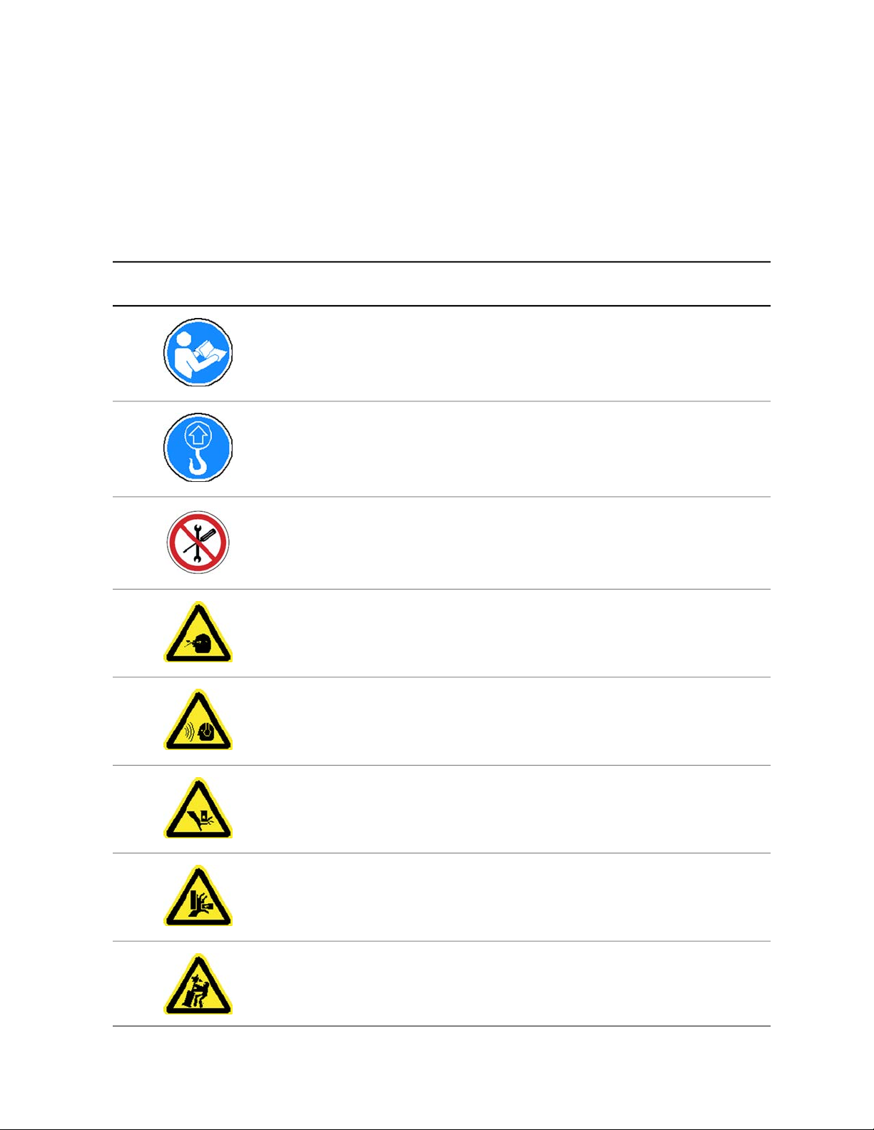
Hazard Warning Icons
The following hazard warning icons indicate hazards that can result in personal injury or equipment damage
when using the MTS Criterion Series 60 systems. They are typically placed on or near the area of concern.
They are intended to alert the user to possible hazardous conditions or hazardous situations.
Hazard Warning Icons
DescriptionIcon
Do not start, operate, or service the machine until you read and understand
the operator's manual.
Failure to do so could result in serious injury.
Lift the machine upright.
The load frame does not contain (or provide access to) any user-serviceable
or adjustable parts. Do not remove fasteners, plates, or covers.
Eye damage hazard. Wear appropriate personal protective equipment, such
as, safety goggles.
Noise hazard. Wear appropriate personal protective equipment, such as, ear
plugs or ear muffs.
Hand crush hazard from moving parts in a downward direction. Stay alert and
be aware of possible moving parts. Keep clear of areas noted with this icon.
Hand crush hazard from moving parts in a sideways direction. Stay alert and
be aware of possible moving parts. Keep clear of areas noted with this icon.
18 | MTS Criterion™Series 60
Possible load frame tipping hazard. The load frame should only be moved by
qualified riggers familiar with moving heavy, delicate equipment. Once in final
operation position, the frame should be bolted to a suitable reaction mass.

DescriptionIcon
Hand crush or pinch point hazard. Stay alert and be aware of possible moving
parts. Keep clear of areas noted with this icon.
The Waste Electrical and Electronic Equipment (WEEE) symbol means that
the controller and its electronic parts must not be disposed of as unsorted
municipal waste. Proper disposal is required by approved electronic waste
collection agencies. Customers in the EC region who desire to return an
end-of-life controller and its electronic parts are encouraged to contact your
local MTS Systems Sales/Service Office for instructions.
You should follow internal safety policies for safe disposal of parts of the
machine. Refer to MSDS for oils and greases that are used on the machine.
Energy Isolation/Lockout/Tagout
Safety
Identify Lockout/Tagout Points
The customer is responsible for establishing a program of energy control procedures, employee training,
and periodic inspections to ensure that, before any employee performs service or maintenance on a
machine or component (where unexpected energizing, startup, or release of stored energy could occur
and cause injury), the machine or component is isolated from the energy source and rendered inoperative
using a supply disconnect (energy isolating) device. The purchase, installation, and use of energy isolating,
lockout, and tagout devices is a customer responsibility.
Lockout devices utilize a positive means, such as a lock, to hold an energy isolating device in the safe
position and prevent energizing a machine or component. Tagout devices consist of a prominent warning
device, such as a tag and means of attachment, which can be securely fastened to an energy isolating
device in accordance with an established procedure, to indicate that the energy isolating device and the
equipment being controlled may not be operated until the tagout device is removed.
The purpose of energy-isolating, lockout, and tagout devices is to provide a positive and effective means
of isolating the test system from the various power sources associated with your system. These power
sources can include (but are not limited to) electrical, hydraulic, water, gas, and air supplies. Each device,
when installed, should provide a single point in the supply circuit where complete system isolation from
supply power or pressure is accomplished when the device is used to interrupt the circuit.
It is important that you are able to isolate the system from its power supplies whenever personnel must
work in proximity to the system. Electricity and heated, cooled, or pressurized fluids or gases are all potential
hazards and the use of isolating devices, lockout, and tagout valves and switches is recommended. In
association with using isolating devices, it is likely that a time interval must be observed to allow latent
pressures, heat, or cold to dissipate from components before working with them
Consider the following:
MTS Criterion™Series 60 | 19

Safety
• You should identify a single control point in your primary electrical supply where complete electrical
isolation can be accomplished. Also, consider that each uninterruptible power supply (UPS) is potentially
an independent (secondary) electrical power source. To determine methods for isolating each UPS as
an electrical supply source, see your vendor-supplied UPS documentation. Before you make contact
with any system circuit, test the circuit with a properly operating circuit tester to ensure that power is
off.
• If your test system is supplied by a hydraulic power unit (HPU) or a facilities hydraulic power unit (FHPU),
you must consider that the hydraulic fluid return lines may be pressurized any time that the HPU is
operating. To view hydraulic schematic circuit details, see the System Documentation CD. Ensure that
you fully understand system supply behavior before you install your lockout/tagout device.
• If your system configuration includes pressure-line accumulators, the lockout/tagout device must be
installed downstream from the accumulators and upstream from the hydraulic service manifold (HSM)
to be effective. Unless you install the lockout/tagout valve in this way, the charged accumulators will
pressurize the line even when the HPU is off and the lockout/tagout valve is closed. Refer to the System
Documentation CD to view hydraulic schematic circuit details. Ensure that you fully understand system
supply behavior before you install your lockout/tagout device.
Site Precautions
Site Precautions
Warning:
The equipment is designed to operate in an environment where precautions have to be taken
to minimize hazards to personnel and the equipment.
Ignoring hazards and failing to take necessary precautions can result in injury or death to
personnel, and damage to equipment.
Do not install or operate the system equipment in a hazardous environment.
Warning:
Hazardous situations or conditions can arise suddenly and without warning at all parts of the
system.
If immediate action is not taken to remove the hazard or remove personnel from the hazard,
serious injury or death can result.
Do not operate the system unless you have full view of the equipment. If operation of the
system takes place in a remote control room (separated from the equipment), it should be
designed so that the operator has full and unobstructed view of the system equipment. Make
sure that ergonomic issues are considered in the layout of the operating area to limit operator
stress and fatigue.
20 | MTS Criterion™Series 60

Warning:
Working environments that are not designed with appropriate ventilation, lighting, heating and
cooling or non-ergonomic equipment, furniture, and equipment/furniture placements can result
in operator fatigue and stress.
Operator fatigue and stress can result in operator errors which can result in injury to personnel
or damage to the equipment and/or specimen.
Make sure that lighting, heating, cooling, and ergonomic issues are considered in the layout
of the operating area to limit operator stress and fatigue.
Guards, Doors, and Covers
Equipment Guards, Doors, and Covers
Safety
Warning:
Guards, doors, and covers are designed to protect personnel from moving parts, electrical
shock, and pressurized fluid or gas.
If guards, doors, and covers are not installed, potential hazards are exposed that can cause
injury or death. Personnel can be struck, crushed, entangled, or drawn into moving parts; hit
by flying objects launched with concussive force by the rapid expansion of pressurized gas;
sprayed from pressurized fluid that can burn and pierce; and electrocuted by exposed electrical
conductors.
Install and close all guards, doors, and covers before applying electrical power and operating
the system.
MTS Criterion™Series 60 | 21

Safety
Equipment Weight and Lift Points
Heavy Equipment Hazards
Warning:
The system components are heavy, and may need to be moved for maintenance, installation,
or decommissioning. If moved, system components require lift equipment capable of handling
their weight.
If the lift equipment fails when system components are moved, the result can be death or
serious injury to personnel, and damage to equipment.
Only qualified personnel should lift, move, or transport equipment. Do not attempt to lift or
move the system components without adequate lift equipment. Use equipment that is rated
for at least 1.5 times the weight of the component. Follow your facility safe-handling procedures
when moving equipment. For weight and lift points, see the appropriate sections of this manual
or the related product manuals.
For instructions and warnings about properly moving the load frame and integrated operations platform,
see the MTS Criterion Series 60 Product Manual.
Safety Practices
General Safety Practices
If you have system related responsibilities (that is, if you are an operator, service engineer, or maintenance
person), you should study this manual carefully before you attempt to perform any test system procedure.
You should receive training on this system or a similar system to ensure a thorough knowledge of your
equipment and the safety issues that are associated with its use. In addition, you should gain an
understanding of system functions by studying the other manuals supplied with your test system. Contact
MTS for information about the content and dates of training classes that are offered.
It is very important that you study the following safety information to ensure that your facility procedures
and the system’s operating environment do not contribute to or result in a hazardous situation. Remember,
you cannot eliminate all the hazards associated with this system, so you must learn and remain aware of
the hazards that apply to your system at all times. Use these safety guidelines to help learn and identify
hazards so that you can establish appropriate training and operating procedures and acquire appropriate
safety equipment (such as gloves, goggles, and hearing protection).
Each test system operates within a unique environment which includes the following known variables:
• Facility variables (facility variables include the structure, atmosphere, and utilities)
22 | MTS Criterion™Series 60

• Unauthorized customer modifications to the equipment
• Operator experience and specialization
• Test specimens
Because of these variables (and the possibility of others), your system can operate under unforeseen
circumstances that can result in an operating environment with unknown hazards.
Improper installation, operation, or maintenance of your system can result in hazardous conditions that
can cause death, personal injury, or damage to the equipment or to the specimen. Common sense and a
thorough knowledge of the system’s operating capabilities can help to determine an appropriate and safe
approach to its operation.
Observe the prescribed safety practices before and during system operation.
It is the customer's responsibility to take the machine out of service and contact MTS Service if discrepancies
in system operation are found.
Safety Practices Before Operating the System
Before you apply power to the test system, review and complete all of the safety practices that are applicable
to your system. The goal, by doing this, is to improve the safety awareness of all personnel involved with
the system and to maintain, through visual inspections, the integrity of specific system components.
Safety
Read all manuals
Study the contents of this manual and the other manuals provided with your system before attempting to
perform any system function for the first time. Procedures that seem relatively simple or intuitively obvious
can require a complete understanding of system operation to avoid unsafe or dangerous situations.
Locate lockout/tagout points
Know where the lockout/tagout point is for each of the supply energies associated with your system. This
includes the hydraulic, pneumatic, electric, and water supplies (as appropriate) for your system to ensure
that the system is isolated from these energies when required.
Know facility safe procedures
Most facilities have internal procedures and rules regarding safe practices within the facility. Be aware of
these safe practices and incorporate them into your daily operation of the system.
Locate Emergency Stop buttons
Know the location of all the system Emergency Stop buttons so that you can stop the system quickly in
an emergency. Ensure that an Emergency Stop button is located within close proximity of the operator at
all times.
Know controls
Before you operate the system for the first time, make a trial run through the operating procedures with
the power off. Locate all hardware and software controls and know what their functions are and what
adjustments they require. If any control function or operating adjustment is not clear, review the applicable
information until you understand it thoroughly.
MTS Criterion™Series 60 | 23

Safety
Have first aid available
Accidents can happen even when you are careful. Arrange your operator schedules so that a properly
trained person is always close by to render first aid. In addition, ensure that local emergency contact
information is posted clearly and in sight of the system operator.
Know potential crush and pinch points
Be aware of potential crush and pinch points on your system and keep personnel and equipment clear of
these areas.
An important consideration for servohydraulic systems is that when power is interrupted, it is likely that
stored accumulator pressure will persist for some time within the system. In addition, it is likely that as
stored energy dissipates, gravity will cause portions of the system to move.
Be aware of component movement with hydraulics off
For hydraulic systems, be aware that mechanical assemblies can shift or drift due to changes within
hydraulic hardware when hydraulics are turned off. This non-commanded movement is because oil can
transfer between the pressure and return ports and across internal components of the hydraulic hardware.
Be aware that this can happen, and clear the area around the mechanical assemblies when hydraulics
are turned off.
Know electrical hazards
When the system electrical power is turned on, minimize the potential for electrical shock hazards. Wear
clothing and use tools that are properly insulated for electrical work. Avoid contact with exposed wiring or
switch contacts.
Whenever possible, turn off electrical power when you work on or in proximity to any electrical system
component. Observe the same precautions as those given for any other high-voltage machinery.
Make sure that all electrical components are adequately grounded. Grounds must remain connected and
undisturbed at all times.
Ensure correct cable connection
If a system cable has been disconnected, ensure that you establish the correct cable-to-connector
relationship during reconnection. Incorrect cable connections can result in improper servo loop phasing
or an open servo loop condition, either of which can cause unstable or unexpected and potentially dangerous
system motions. Verify the correct cable-to-connector relationship by observing the cable and connector
labeling and the system wiring schematics.
Keep bystanders safely away
Keep bystanders at a safe distance from all equipment. Never allow bystanders to be in close proximity
of specimens or equipment while the test is running.
Wear proper clothing
Do not wear neckties, shop aprons, loose clothing or jewelry, or long hair that could get caught in equipment
and result in an injury. Remove loose clothing or jewelry and restrain long hair.
24 | MTS Criterion™Series 60

Safety
Remove flammable fluids
Remove flammable fluids from their containers or from components before you install the container or
component. If desired, you can replace the flammable fluid with a non-flammable fluid to maintain the
proper proportion of weight and balance.
Know compressed gas hazards
Your system may contain accumulators that require a high-pressure gas precharge (pressures that exceed
138 bar [2000 psi]). High-pressure devices are potentially dangerous because a great amount of energy
is available in the event of an uncontrolled expansion or rupture.
Observe the following safety practices when you work with high-pressure air or gases:
• When you charge an accumulator, follow all the charging instructions provided in the appropriate product
information manuals. When precharging accumulators, properly identify the type of gas to be used and
the type of accumulator to be precharged.
• Use only dry-pumped nitrogen to precharge nitrogen-charged accumulators. (Dry-pumped nitrogen
can also be labeled “oil pumped” or “dry water pumped.”) Do not use compressed air or oxygen for
precharging: the temperature increase caused by rapid gas compression can result in highly explosive
conditions when hydraulic fluid is in the presence of oxygen or compressed air.
• Always follow the recommended bleeding procedures before you remove or disassemble components
that contain pressurized gas. When you bleed a gas or remove a fitting, hose, or component that
contains a gas, remember that many gases cannot support life. Therefore, as the ratio of released gas
to oxygen increases, so does the potential for suffocation.
• Wear appropriate safety devices to protect your hearing. Escaping air or gas can create a noise level
that can damage your hearing.
• Ensure that all pressurized air or gas is bled out of a pneumatic or gas-charged device before you start
to disassemble it. A thorough understanding of the assembly and its pressurized areas is necessary
before you undertake any maintenance. Refer to the appropriate product information for the correct
bleeding procedure.
It may not be obvious or intuitive which bolts or fittings are used to restrain a pressurized area. On
some assemblies, you must remove a cover plate to gain access to the structural bolts. Sometimes, to
protect you from a rapid release of trapped gases, a small port is exposed when you remove this cover
plate. Exposing this port ensures that the gas precharge is fully bled before disassembly. However,
this is not the recommended procedure for bleeding a pneumatic or gas-charged device, because it
can expose you to the dangers of escaping compressed gas and particulates that are expelled from
the chamber or around the seals. Do not assume that cover plates and ports are installed in all the
critical locations.
Consult MTS when in doubt about the safety or reliability of any system-related procedure or modification
that involves devices that contain any type of compressed gas.
Check bolt ratings and torques
To ensure a reliable product, fasteners (such as bolts and tie rods) used in MTS-manufactured systems
are torqued to specific requirements. If a fastener is loosened or the configuration of a component within
the system is modified, see the system and component assembly drawings (located on the System
Documentation CD) to determine the correct fastener, fastener rating, and torque. Over torquing or under
torquing a fastener can create a hazardous situation due to the high forces and pressures present in MTS
test systems.
MTS Criterion™Series 60 | 25

Safety
On rare occasions, a fastener can fail even when it is correctly installed. Failure usually occurs during
torquing, but it can occur several days later. Failure of a fastener can result in a high velocity projectile.
Therefore, it is a good practice to avoid stationing personnel in line with or below assemblies that contain
large or long fasteners.
Practice good housekeeping
Keep the floors in the work area clean. Industrial chemicals, such as hydraulic fluid, that are spilled on any
type of floor can result in a dangerous, slippery surface. Do not leave tools, fixtures, or other items not
specific to the test lying about on the floor, system, or decking.
Protect hoses and cables
Protect electrical cables from spilled fluids and from excessive temperatures that can cause the cables to
harden and eventually fail. Ensure that all cables have appropriate strain relief devices installed at the
cable and near the connector plug. Do not use the connector plug as a strain relief.
Protect all system hoses and cables from sharp or abrasive objects that can cause the hose or cable to
fail. Use a cable cover or cable tray where cables are in traffic locations. Never walk on hoses or cables
or move heavy objects over them. Route hoses and cables away from areas that expose them to possible
damage.
Provide proper hydraulic fluid filtration
For hydraulic systems equipped with a non-MTS hydraulic power unit, make sure that hydraulic fluid
filtration is established to maintain fluid cleanliness standards as stated in the Hydraulic Fluid Care Manual
(see the System Documentation CD). Particles present in the hydraulic fluid can cause erratic or poor
system response.
Protect accumulators from moving objects
For systems equipped with accumulators, protect accumulators with supports or guards. Do not strike
accumulators with moving objects. This could cause the accumulator(s) to separate from the manifold
resulting in equipment damage and personal injury.
Record changes
If you change any operating procedure, write the change and the date of the change in the appropriate
manual.
Provide test area guards
Use protective guards such as cages, enclosures, and special laboratory layouts when you work with
hazardous test specimens (for example, brittle or fragmenting materials or materials that are internally
pressurized).
Do not exceed the Maximum Supply Pressure
For hydraulic systems and components, make sure that hydraulic supply pressure is limited to the maximum
pressure defined by the system operating limits. Read and review “System Operating Limits” for the system.
Do not disable safety devices
Your system may have active or passive safety devices installed to prevent system operation if the device
indicates an unsafe condition. Do not disable such devices as it may result in unexpected system motion.
26 | MTS Criterion™Series 60

Use appropriately sized fuses
Whenever you replace fuses for the system or supply, ensure that you use a fuse that is appropriately
sized and correctly installed. Undersized or oversized fuses can result in cables that overheat and fuses
that explode. Either instance creates a fire hazard.
Provide adequate lighting
Ensure adequate lighting to minimize the chance of operation errors, equipment damage, and personal
injury.
Provide adequate ventilation
Make sure work and maintenance areas are adequately ventilated to minimize the risks associated with
the collection of hazardous fumes (such as vaporized hydraulic fluid). This is of special concern in confined
areas where hydraulic equipment is operating at high pressure in confined areas.
Provide means to access out-of-reach components
Make sure you can access system components that might be out of reach while standing on the floor. For
example, ladders or scaffolding might be required to reach load cell connectors on tall load units.
Safety Practices While Operating the System
Safety
Wear appropriate personal protection
Wear eye protection when you work with high-pressure hydraulic fluid, high-pressure air pressure, breakable
specimens, or when anything characteristic to the specimen could break apart.
Wear ear protection when you work near electric motors, pumps, or other devices that generate high noise
levels. This system may create sound pressure levels that exceed 70 dbA during operation.
Wear appropriate protection (gloves, boots, suits, respirators) whenever you work with fluids, chemicals,
or powders that may irritate or harm the skin, respiratory system, or eyes.
Provide test area enclosures
Use protective enclosures such as cages or shields, and special laboratory layouts when you work with
hazardous test specimens (for example, brittle or fragmenting materials or materials that are internally
pressurized).
You must evaluate risks due to ejected parts or materials from the test specimens. If the MTS Test Area
Enclosure option is not purchased by the customer, then for protection against ejected parts or materials
from test specimens and to control access to the machinery, the Customer must provide a Test Area
Enclosure to protect personnel.
Specimen temperature changes
During cyclic testing, the specimen temperature can become hot enough to cause burns. Wear personal
protection equipment (gloves) when handling specimens.
Handle chemicals safely
Whenever you use or handle chemicals (for example, hydraulic fluid, batteries, contaminated parts, electrical
fluids, and maintenance waste), see the appropriate MSDS documentation for that material and determine
MTS Criterion™Series 60 | 27

Safety
the appropriate measures and equipment required to handle and use the chemical safely. Ensure that the
chemical is disposed of appropriately.
Know servohydraulic system interlocks
Interlock devices should always be used and properly adjusted. Interlock devices are designed to minimize
the chance of accidental damage to the test specimen or the equipment. Test all interlock devices for
proper operation immediately before a test. Do not disable or bypass any interlock devices as doing so
could allow hydraulic pressure to be applied regardless of the true interlock condition. The Reset/Override
button is a software function that can be used to temporarily override an interlock while attempting to start
the hydraulic power unit and gain control of the system.
Know system limits
Never rely on system limits such as mechanical limits or software limits to protect you or any personnel.
System limits are designed to minimize the chance of accidental damage to test specimens or to equipment.
Test all limits for proper operation immediately before a test. Always use these limits and adjust them
properly.
Do not disturb sensors
Do not bump, wiggle, adjust, disconnect, or otherwise disturb a sensor (such as an accelerometer or
extensometer) or its connecting cable when hydraulic pressure is applied.
Ensure secure cables
Ensure that all cable connections (electrical supply, control, feedback, sensor, communications, and so
forth) are either locking type, or are secured, to ensure that they cannot be disconnected by a simple act.
Do not change any cable connections when electrical power or hydraulic pressure is applied. If you attempt
to change a cable connection while the system is in operation, an open control loop condition can result.
An open control loop condition can cause a rapid, unexpected system response which can result in severe
personal injury, death, or damage to equipment. Also, ensure that all cables are connected after you make
any changes in the system configuration.
Stay alert
Avoid long periods of work without adequate rest. In addition, avoid long periods of repetitious, unvarying,
or monotonous work because these conditions can contribute to accidents and hazardous situations. If
you are too familiar with the work environment, it is easy to overlook potential hazards that exist in that
environment.
Contain small leaks
Do not use your fingers or hands to stop small leaks in hydraulic or pneumatic hoses. Substantial pressures
can build up, especially if the hole is small. These high pressures may cause the oil or gas to penetrate
your skin, causing painful and dangerously infected wounds. Turn off the hydraulic supply and allow the
hydraulic pressure to dissipate before you remove and replace the hose or any pressurized component.
Stay clear of moving equipment/avoid crush points
Stay clear of mechanical linkages, connecting cables, and hoses that move because you may get pinched,
crushed, tangled, or dragged along with the equipment. High forces generated by the system can pinch,
cut, or crush anything in the path of the equipment and cause serious injury. Stay clear of any potential
crush points. Most test systems can produce sudden, high-force motion. Never assume that your reactions
are fast enough to allow you to escape injury when a system fails.
28 | MTS Criterion™Series 60

Safety
Know the causes of unexpected actuator motions
The high force and velocity capabilities of MTS actuators can be destructive and dangerous (especially if
actuator motion is unexpected). The most likely causes of unexpected actuator response are operator
error and equipment failure due to damage or abuse (such as broken, cut, or crushed cables and hoses;
shorted wires; overstressed feedback devices; and damaged components within the servocontrol loop).
Eliminate any condition that could cause unexpected actuator motion.
Do not use RF transmitters
Keep radio frequency (RF) transmitters away from the workstation computers, remote terminals, and
electronics consoles. Intense RF fields can cause erratic operation of the more sensitive circuits in the
system.
MTS Criterion™Series 60 | 29
 Loading...