


 Loading...
m
be certain.
Series 505 SilentFlo™ Hydraulic Power Unit
Product Information
Model 505.07
Model 505.11
100-007-837 T
Copyright information Trademark information
© 1999–2010 MTS Systems Corporation. All rights reserved.
MTS and SilentFlo are registered trademarks of MTS Systems Corporation within the United States. These trademarks may be protected in other countries.
DTE is a registered trademark of Exxon Mobil Corporation. Tellus is a registered trademark of Shell Oil Corporation. Molykote is a registered trademark of Dow Chemical Corporation. Synasol is a registered trademark of Union Carbide Corporation. All other trademarks or service marks are property of their respective owners.
Publication information |
MANUAL PART NUMBER |
PUBLICATION DATE |
|
|
|
|
100-007-837 A |
July 1999 |
|
|
|
|
100-007-837 B |
August 1999 |
|
|
|
|
100-007-837 C |
March 2000 |
|
|
|
|
100-007-837 D |
July 2001 |
|
|
|
|
100-007-837 E |
September 2001 |
|
|
|
|
100-007-837 F |
May 2002 |
|
|
|
|
100-007-837 G |
February 2003 |
|
|
|
|
100-007-837 H |
July 2003 |
|
|
|
|
100-007-837J |
November 2003 |
|
|
|
|
100-007-837 K |
July 2005 |
|
|
|
|
100-007-837 L |
June 2006 |
|
|
|
|
100-007-837 M |
August 2006 |
|
|
|
|
100-007-837 N |
February 2008 |
|
|
|
|
100-007-837 P |
November 2008 |
|
|
|
|
100-007-837 R |
April 2009 |
|
|
|
|
100-007-837 S |
January 2010 |
|
|
|
|
100-007-837 T |
April 2010 |
|
|
|

Contents
Technical Support |
5 |
|
|
|
|
||
|
How to Get Technical Support |
5 |
|
|
|||
|
Before You Contact MTS |
5 |
|
|
|
||
|
If You Contact MTS by Phone |
6 |
|
|
|||
|
Problem Submittal Form in MTS Manuals 7 |
||||||
Preface |
9 |
|
|
|
|
|
|
|
|
|
|
|
|
|
|
|
Before You Begin |
9 |
|
|
|
|
|
Conventions |
10 |
|
|
|
|
|
|
|
Documentation Conventions |
10 |
|
|
|||
Introduction |
13 |
|
|
|
|
|
|
|
|
|
|
|
|
|
|
|
EU Declarations |
13 |
|
|
|
|
|
|
Component Identification |
14 |
|
|
|
||
|
Functional Description 15 |
|
|
|
|
||
|
505.07/.11 HPU Hydraulic Schematic |
17 |
|||||
|
Auto-Cooling Valve (adjustable) |
18 |
|
||||
|
Electrical Control |
18 |
|
|
|
|
|
|
505.07 HPU Electrical Schematic |
19 |
|
||||
|
505.11 HPU Electrical Schematic |
21 |
|
||||
|
Series 505 HPU General Specifications |
23 |
|||||
Safety |
25 |
|
|
|
|
|
|
|
|
||||||
|
General Safety Practices: Hydraulic Power Units and Hydraulic Service Manifolds 25 |
||||||
Installation |
33 |
|
|
|
|
|
|
|
|
|
|
|
|
|
|
|
Install the HPU |
33 |
|
|
|
|
|
Model 505.07/.11 SilentFlo™ HPU |
Contents |
3 |

Operation |
37 |
|
|
|
|
|
|
505.07/.11 HPU Controls |
38 |
|
|
|
|||
Operating the HPU Locally or Remotely |
40 |
||||||
Recovering from an Interlock |
41 |
|
|
||||
Changing the Water Flow |
42 |
|
|
|
|||
Resetting the Thermal Overloads |
43 |
|
|||||
Adjusting the Hydraulic Pressure |
44 |
|
|||||
Adjusting the HPU Output Pressure Level 45 |
|||||||
Adjusting the Auto-Cooling Level |
45 |
|
|||||
Low/High Pressure Functionality |
49 |
|
|||||
Maintenance |
53 |
|
|
|
|
||
|
|
|
|||||
Routine Maintenance Overview Checklist |
54 |
|
|||||
505.07/.11 HPU Maintenance Schedule |
56 |
||||||
Checking the Hydraulic Fluid |
58 |
|
|
||||
Replacing the Return Line Filter |
59 |
|
|||||
Sample the Hydraulic Fluid 62 |
|
|
|||||
Appearance of Hydraulic Fluid Sample |
63 |
||||||
Replacing the Hydraulic Fluid |
64 |
|
|||||
Accessories |
67 |
|
|
|
|
||
|
|
|
|
|
|||
High Pressure Filter Kit |
68 |
|
|
|
|||
Surge Suppressor Kit 69 |
|
|
|
|
|||
Precharging the Surge Suppressor Accumulator 71 |
|||||||
Lifting Kit |
74 |
|
|
|
|
||
Caster Kit |
75 |
|
|
|
|
||
Appendix A: HPU Maintenance and Service Logs 77 |
|||||||
|
|
|
|
|
|
|
|
8 Hours/Daily |
78 |
|
|
|
|
|
|
40 Hours/Weekly |
79 |
|
|
|
|
||
160 Hours/Biweekly |
80 |
|
|
|
|
||
500 Hours 81 |
|
|
|
|
|
|
|
1000 Hours |
82 |
|
|
|
|
|
|
2000 Hours |
83 |
|
|
|
|
|
|
5000 Hours |
84 |
|
|
|
|
|
|
10,000 Hours |
85 |
|
|
|
|
|
|
4 |
Contents |
Model 505.07/.11 SilentFlo™ HPU |

How to Get Technical Support
Technical Support
How to Get Technical Support
Start with your manuals
Technical support methods
www.mts.com
Telephone
Fax
Outside the U.S.
The manuals supplied by MTS provide most of the information you need to use and maintain your equipment. If your equipment includes software, look for online help and README files that contain additional product information.
If you cannot find answers to your technical questions from these sources, you can use the Internet, e-mail, telephone, or fax to contact MTS for assistance.
MTS provides a full range of support services after your system is installed. If you have any questions about a system or product, contact Technical Support in one of the following ways.
The web site provides access to our technical support staff by means of an onlineform:
www.mts.com > Contact MTS > Service & Technical Support button
tech.support@mts.com
MTS Call Center 800-328-2255
Weekdays 7:00 A.M. to 5:00 P.M., Central Time
952-937-4515
Please include “Technical Support” in the subject line.
For technical support outside the United States, contact your local sales and service office. For a list of worldwide sales and service locations and contact information, use the Global MTS link at the MTS web site:
www.mts.com > Global MTS > (choose your region in the right-hand column) > (choose the location closest to you)
Before You Contact MTS
Know your site number and system number
MTS can help you more efficiently if you have the following information available when you contact us for support.
The site number contains your company number and identifies your equipment type (such as material testing or simulation). The number is typically written on a label on your equipment before the system leaves MTS. If you do not know your MTS site number, contact your sales engineer.
Example site number: 571167
When you have more than one MTS system, the system job number identifies your system. You can find your job number in your order paperwork.
Example system number: US1.42460
Model 505.07/.11 SilentFlo™ HPU |
Technical Support |
5 |
If You Contact MTS by Phone
Know information from |
If you have contacted MTS about this problem before, we can recall your file |
|
prior technical |
based on the: |
|
assistance |
• |
MTS notification number |
|
||
|
• |
Name of the person who helped you |
Identify the problem |
Describe the problem and know the answers to the following questions: |
|
|
• |
How long and how often has the problem occurred? |
|
• |
Can you reproduce the problem? |
|
• |
Were any hardware or software changes made to the system before the |
|
|
problem started? |
|
• |
What are the equipment model numbers? |
|
• |
What is the controller model (if applicable)? |
|
• |
What is the system configuration? |
Know relevant For a computer problem, have the following information available:
computer information
•Manufacturer’s name and model number
•Operating software type and service patch information
•Amount of system memory
•Amount of free space on the hard drive where the application resides
•Current status of hard-drive fragmentation
•Connection status to a corporate network
Know relevant For software application problems, have the following information available:
software information
•The software application’s name, version number, build number, and (if available) software patch number. This information can typically be found in the About selection in the Help menu.
•The names of other applications on your computer, such as:
–Anti-virus software
–Screen savers
–Keyboard enhancers
–Print spoolers
–Messaging applications
If You Contact MTS by Phone
A Call Center agent registers your call before connecting you with a technical support specialist. The agent asks you for your:
•Site number
6 |
Technical Support |
Model 505.07/.11 SilentFlo™ HPU |
Identify system type
Be prepared to troubleshoot
Write down relevant information
After you call
Problem Submittal Form in MTS Manuals
•Name
•Company name
•Company address
•Phone number where you can be reached
If your issue has a notification number, please provide that number. A new issue will be assigned a unique notification number.
To enable the Call Center agent to connect you with the most qualified technical support specialist available, identify your system as one of the following types:
•Electromechanical material test system
•Hydromechanical material test system
•Vehicle test system
•Vehicle component test system
•Aero test system
Prepare to perform troubleshooting while on the phone:
•Call from a telephone close to the system so that you can implement suggestions made over the phone.
•Have the original operating and application software media available.
•If you are not familiar with all aspects of the equipment operation, have an experienced user nearby to assist you.
In case Technical Support must call you:
•Verify the notification number.
•Record the name of the person who helped you.
•Write down any specific instructions.
MTS logs and tracks all calls to ensure that you receive assistance for your problem or request. If you have questions about the status of your problem or have additional information to report, please contact Technical Support again and provide your original notification number.
Problem Submittal Form in MTS Manuals
Use the Problem Submittal Form to communicate problems with your software, hardware, manuals, or service that are not resolved to your satisfaction through the technical support process. The form includes check boxes that allow you to indicate the urgency of your problem and your expectation of an acceptable response time. We guarantee a timely response—your feedback is important to us.
Access the Problem Submittal Form:
Model 505.07/.11 SilentFlo™ HPU |
Technical Support |
7 |
Problem Submittal Form in MTS Manuals
•In the back of many MTS manuals (postage paid form to be mailed to MTS)
•www.mts.com > Contact Us > Problem Submittal Form button (electronic form to be e-mailed to MTS)
8 |
Technical Support |
Model 505.07/.11 SilentFlo™ HPU |

Before You Begin
Preface
Before You Begin
Safety first!
Other MTS manuals
Before you use your MTS product or system, read and understand the Safety manual and any other safety information provided with your system. Improper installation, operation, or maintenance can result in hazardous conditions that can cause severe personal injury or death, or damage to your equipment and specimen. Again, read and understand the safety information provided with your system before you continue. It is very important that you remain aware of hazards that apply to your system.
In addition to this manual, you may receive additional manuals in paper or electronic form.
You may also receive an MTS System Documentation CD. It contains an electronic copy of the manuals that pertain to your test system, such as:
•Hydraulic and mechanical component manuals
•Assembly drawings
•Parts lists
•Operation manual
•Preventive maintenance manual
Controller and application software manuals are typically included on the software CD distribution disc(s).
Model 505.07/.11 SilentFlo™ HPU |
Preface |
9 |

Conventions
Conventions
Documentation Conventions
The following paragraphs describe some of the conventions that are used in your
MTS manuals.
Hazard conventions Hazard notices may be embedded in this manual. These notices contain safety information that is specific to the activity to be performed. Hazard notices immediately precede the step or procedure that may lead to an associated hazard. Read all hazard notices carefully and follow all directions and recommendations. Three different levels of hazard notices may appear in your manuals. Following are examples of all three levels.
Note For general safety information, see the safety information provided with your system.

 DANGER
Danger notices indicate the presence of a hazard with a high level of risk which, if ignored, will result in death, severe personal injury, or substantial property damage.

 WARNING
Warning notices indicate the presence of a hazard with a medium level of risk which, if ignored, can result in death, severe personal injury, or substantial property damage.

 CAUTION
Notes
Special terms
Illustrations
Electronic manual conventions
Caution notices indicate the presence of a hazard with a low level of risk which, if ignored, could cause moderate or minor personal injury or equipment damage, or could endanger test integrity.
Notes provide additional information about operating your system or highlight easily overlooked items. For example:
Note Resources that are put back on the hardware lists show up at the end of the list.
The first occurrence of special terms is shown in italics.
Illustrations appear in this manual to clarify text. They are examples only and do not necessarily represent your actual system configuration, test application, or software.
This manual is available as an electronic document in the Portable Document File (PDF) format. It can be viewed on any computer that has Adobe Acrobat Reader installed.
10 Preface |
Model 505.07/.11 SilentFlo™ HPU |
Documentation Conventions
Hypertext links The electronic document has many hypertext links displayed in a blue font. All blue words in the body text, along with all contents entries and index page numbers, are hypertext links. When you click a hypertext link, the application jumps to the corresponding topic.
Model 505.07/.11 SilentFlo™ HPU |
Preface |
11 |
Documentation Conventions
12 Preface |
Model 505.07/.11 SilentFlo™ HPU |

EU Declarations
Introduction
The MTS Model 505.07 Hydraulic Power Unit (HPU) and Model 505.11 HPU provide high-pressure hydraulic fluid for test system operation. This section contains the functional description and the specifications of the HPU.
Contents |
Component Identification 14 |
|
|
|
Functional Description 15 |
|
|
|
505.07/.11 HPU Hydraulic Schematic |
17 |
|
|
Auto-Cooling Valve (adjustable) |
18 |
|
|
Electrical Control 18 |
|
|
|
505.07 HPU Electrical Schematic |
19 |
|
|
505.11 HPU Electrical Schematic |
21 |
|
|
Series 505 HPU General Specifications |
23 |
|
EU Declarations
EC Declaration of
Conformity (Machinery
Directive 2006/42/EC
Annex II 1A)
If applicable, a Declaration of Conformity is supplied with the machinery; an example of the Declaration of Conformity is provided at the end of this manual.
Model 505.07/.11 SilentFlo™ HPU |
Introduction 13 |

Component Identification
Component Identification
Control Panel |
Nameplate |
Output |
|
Pressure |
|
||
|
|
||
(other side of box) |
|
Gage |
Auto-Cooling |
|
Electrical Enclosure |
|
|
Power Discon Switch |
|
Valve |
|
|
|
|
|
(other side of box) |
Low Level/ |
|
Pressure Relief |
|
|
||
|
Overtemperature |
|
Valve |
|
Sensor |
|
|
Return |
Fluid Level Gage |
|
Fluid Sample |
Filter |
Filler Cap |
|
|
|
Port |
||
|
|
|
Temperature |
Control Manifold |
|
Gage |
||
(shown rotated) |
||
|
Heat
Exchanger
Output
Pressure
Control
High Pressure |
|
|
Filter Location |
|
Surge Supressor |
(optional–not |
|
|
|
Mounted to Pump |
|
shown) |
|
|
|
(optional) |
|
|
|
|
Drain Valve |
Water Flow |
Hydraulic and Water |
|
||
|
Regulator |
Connections |
|
Component Locations |
|
|
Component Descriptions (part 1 of 2) |
|
COMPONENT |
DESCRIPTION |
|
Auto-Cooling Valve |
Keeps the hydraulic fluid clean and cool by circulating the fluid through the |
|
|
return filter and the heat exchanger while the HPU is in high pressure mode |
|
|
and the fluid demand by the external circuit is very low. |
|
Control Panel |
Controls the operation of the power unit and indicates the current status of |
|
|
several detectors. |
|
Electrical Enclosure |
Houses the electrical and control components of the HPU. The main power |
|
|
lines enter the unit at the top. The power disconnect switch removes electrical |
|
|
power whenever the enclosure door is opened. |
|
Filler Cap |
Vents the hydraulic fluid reservoir. This is where you add hydraulic fluid. |
|
Filter |
Filters particles out of the hydraulic fluid as it is returned to the HPU. |
|
14 Introduction |
Model 505.07/.11 SilentFlo™ HPU |
|
Functional Description |
|
Component Descriptions (part 2 of 2) |
COMPONENT |
DESCRIPTION |
|
|
Drain Valve |
Drains the hydraulic fluid from the reservoir. |
|
|
Fluid Level Gage |
Displays the level of the hydraulic fluid. |
|
|
Fluid Sample Port |
Access port for obtaining hydraulic fluid samples from the HPU. A quick |
|
disconnect port is provided. Use the optional sampling kit that includes a |
|
needle valve to regulate the flow through the sample port. |
|
|
Heat Exchanger |
Cools the hydraulic fluid by using an oil-to-water heat exchanger. The heat |
|
exchanger removes most of the heat generated by the HPU. |
|
|
Hydraulic and Water |
Connection points for the hydraulic fluid distribution system, water source, |
Connections |
and return lines. |
|
|
Low level/Overtemperature |
Senses the hydraulic fluid level and temperature. Control interlocks |
Sensor |
automatically shut the HPU down if the fluid level drops too low or the |
|
hydraulic fluid temperature rises above the temperature sensor’s setting. |
|
|
Output Pressure Control |
Sets the output pressure of the HPU. |
|
|
Output Pressure Gage |
Displays the hydraulic pressure being output from the HPU. |
|
|
Nameplate |
Provides basic product information such as model number, serial number, and |
|
electrical information. |
|
|
Power Disconnect Switch |
Disconnects the incoming power from the HPU. The switch is a lockable, |
|
mechanical latch. Power is removed whenever the door to the electrical |
|
enclosure is open (the switch is in the off position). However, incoming power |
|
lines to the switch are live unless power is removed externally. |
|
|
Pressure Relief Valve |
Prevents the HPU from exceeding 22.4 MPa (3250 psi). |
|
|
Reservoir |
Holds the hydraulic fluid and houses the hydraulic pump and motor. |
|
|
Temperature Gage |
Displays the temperature of the hydraulic fluid. |
|
|
Water Flow Regulator |
Sets the amount of water flowing through the heat exchanger. Adjust the water |
|
flow to regulate the temperature of the hydraulic fluid. |
|
|
Functional Description
Pump A variable volume pump draws hydraulic fluid from the reservoir and pressurizes it to the adjusted output pressure, typically 21 MPa (3000 psi). A check valve prevents hydraulic fluid from being siphoned back into the reservoir. The pressurized fluid is controlled by a control manifold that contains the high/low pressure solenoid valve and a non-adjustable relief valve set at 22.4 MPa (3250 psi).
Pressure The start/low/high switch on the front panel of the electrical enclosure controls the hydraulic pressure of the HPU. The start/low/high switch operates like an automotive ignition switch; turn and hold the switch in the start position until the motor starts running. The switch returns to the low position.
Model 505.07/.11 SilentFlo™ HPU |
Introduction 15 |
Functional Description
Filtering
Heat exchanger
The unit automatically starts in low pressure to reduce the amperage needed for starting, which will extend pump and motor life. When operating at this setting, low-pressure fluid is available to the hydraulic circuit. Low pressure is achieved by diverting a portion of the hydraulic fluid through the high pressure solenoid and returning it to the reservoir. Selecting high pressure blocks the low pressure return path and makes all of the pressurized hydraulic fluid available to the hydraulic circuit.
The output pressure can be adjusted from about 1 MPa (145 psi) to 21 MPa (3000 psi). The HPU is designed to provide 21 MPa (3000 psi). A nonadjustable relief valve is set at 22.4 MPa (3250 psi) to protect the hydraulic system from excessive pressure.
As hydraulic fluid returns to the reservoir, it is filtered by a 3-micron element. This ensures that all hydraulic fluid is filtered whether it travels out through the circuit or returns by way of the unit’s control manifold under low pressure. Filter cleanliness is automatically monitored. An indicator lights on the front panel signaling when the filter needs an element change.
Hydraulic fluid temperature is maintained with a heat exchanger that cools the fluid. The water-cooled heat exchanger cools the hydraulic fluid as it passes over water-filled plates. A regulating valve monitors the temperature of the hydraulic fluid and adjusts the flow of water through the plates. The flow of cooling water regulates the temperature of the hydraulic fluid.
•The typical operating temperature range of the hydraulic fluid is 43–49°C (110–120°F).
•If the hydraulic fluid temperature exceeds 55ºC (131ºF), a switch opens and shuts down the HPU.
•When the HPU is shut off, the flow of water is also stopped by a shutoff solenoid valve.
Note For additional information see the Heat Exchanger Care and Water Quality Guide (part number 015-164-000).
16 Introduction |
Model 505.07/.11 SilentFlo™ HPU |

|
|
|
|
505.07/.11 HPU Hydraulic Schematic |
||||
505.07/.11 HPU Hydraulic Schematic |
|
|
|
|
|
|||
|
|
The hydraulic schematic shows the functional layout of the Series 505 Hydraulic |
||||||
|
|
Power Unit. |
|
|
|
|
|
|
|
|
|
|
P |
R |
D D |
W |
W |
|
|
|
|
0.06 inch Orifice |
|
|
|
|
|
|
Pressure |
0.007 MPa (1.0 psi) |
|
|
|
|
|
|
|
|
Filter |
|
|
|
|
|
|
|
(optional) |
|
|
|
|
|
|
Pressure |
Accumulator |
|
|
|
|
|
|
|
|
|
|
|
|
|
|
||
|
Gage |
|
|
|
|
|
|
|
|
|
|
|
Oil Sample |
|
|
|
|
|
|
|
|
Port |
|
|
|
|
Check |
|
|
|
|
|
|
|
Water |
|
|
|
|
|
|
|
Shutoff |
|
Valve |
|
|
|
Optional |
|
|
|
|
|
|
|
|
|
|
Valve |
||
|
|
|
|
|
|
|
||
|
|
|
|
Pressure |
|
|
|
|
|
|
Auto-cooling |
Port |
|
|
|
|
|
|
|
|
|
|
|
|
||
|
|
|
Valve |
|
|
|
|
|
High Pressure |
|
(adjustable) |
|
|
|
|
|
|
|
|
|
|
|
|
|
|
|
Solenoid Valve |
|
|
|
Pressure |
|
|
|
|
|
|
|
|
|
|
|
Water |
|
|
|
|
|
Relief Valve |
|
|
|
|
|
|
Auto-cooling |
|
(factory set at |
|
|
|
Regulator |
|
|
|
22.4 MPa (3250 psi) |
|
|
|
Valve |
|
|
|
Valve |
|
|
|
|
||
|
|
(factory set) |
|
|
|
|
|
|
|
|
Control Manifold |
|
|
|
|
|
|
|
|
Temperature |
Sight |
|
|
|
|
|
|
|
Gage |
Gage |
Heat |
|
|
|
|
|
|
|
|
Exchanger |
|
|
|
|
Temperature |
|
|
|
Pump Drain |
|
|
|
|
and Low Level |
Surge |
|
|
|
|
|
|
|
Sensor |
|
|
Check Valve |
|
|
|
|
|
Suppressor |
|
|
|
|
|
|||
|
|
0.007 MPa (1.0 psi) |
|
|
|
|
||
|
(optional) |
|
|
|
|
|
|
|
|
|
|
|
|
|
|
|
|
|
|
|
|
3 Micron |
|
|
|
|
|
|
|
|
Filter |
|
|
|
|
|
|
|
|
Pump Drain |
|
|
|
|
|
Motor |
Pump |
|
Check Valve |
|
|
|
|
|
|
0.034 MPa (5.0 psi) |
|
|
|
|
||
|
|
|
Reservoir |
|
|
|
|
|
Model 505.07/.11 SilentFlo™ HPU |
Introduction 17 |
Auto-Cooling Valve (adjustable)
Auto-Cooling Valve (adjustable)
The auto-cooling function is integrated into the control manifold. During periods of low flow demand from the external hydraulic circuit, this feature provides two important benefits: a re-circulating flow that ensures hydraulic fluid filtering whenever the unit is on, and safeguarding against hydraulic fluid overtemperature. It functions by opening a hydraulic flow path through the fluid conditioning circuit when external hydraulic demand for flow is low. When the external demand increases, this feature closes the path to provide the full flow of the HPU to the external demand.
The effective operating range of the auto-cooling circuit is between system pressures of 14 MPa (2000 psi) to 21 MPa (3000 psi). In order for the AutoCooling Valve to function properly, it must be re-adjusted anytime the output pressure will be changed for longer than 10 minutes.
Note If the test condition requires a maximum pressure level less than 14 MPa (2000 psi), consult MTS.
Electrical Control
The HPU can be controlled locally using the front panel controls, or remotely through a controller via the J1 connector. The controls included in the electrical enclosure include the following:
•A start/low/high switch ensures that the system starts in low pressure, and permits quick selection of low or high pressure. Wye-delta starting (505.11 only) reduces the initial current rush to the motor when electrical service to the HPU is turned on.
•Thermal overload indicators protect the HPU from excessive current draw.
•A latchable Stop button prevents inadvertent starts.
•Interlocks protect the HPU against low hydraulic fluid level, overtemperature, and dirty filters.
•Front panel indicators provide a quick indication of the unit’s condition. These include power on, low level, overtemperature, and dirty filter lights.
–A Reset button brings the unit back into operation after a fault has been detected and corrected.
–A dirty filter signal will not shut the unit down, but will prevent the unit from starting.
•An hour meter is provided to help you determine maintenance intervals.
•The power disconnect switch on the door of the electrical enclosure ensures that power is removed whenever the door is opened. It is a lockable, maindisconnect switch.
18 Introduction |
Model 505.07/.11 SilentFlo™ HPU |
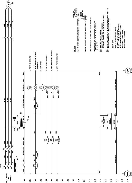
505.07 HPU Electrical Schematic
505.07 HPU Electrical Schematic
The electrical schematic shows the electrical layout of the Model 505.07
Hydraulic Power Unit.
Model 505.07/.11 SilentFlo™ HPU |
Introduction 19 |

505.07 HPU Electrical Schematic
20 Introduction |
Model 505.07/.11 SilentFlo™ HPU |

505.11 HPU Electrical Schematic
505.11 HPU Electrical Schematic
The electrical schematic shows the electrical layout of the Model 505.11
Hydraulic Power Unit.
Model 505.07/.11 SilentFlo™ HPU |
Introduction 21 |

505.11 HPU Electrical Schematic
22 Introduction |
Model 505.07/.11 SilentFlo™ HPU |

Series 505 HPU General Specifications
Series 505 HPU General Specifications
|
General Specifications |
PARAMETER |
SPECIFICATION |
|
|
Environmental |
For use in a controlled environment |
Operating temperature |
5–40°C (41–104°F) |
Humidity |
0–85% noncondensing |
Heat load |
<630 kcal/hr (2500 BTU/hr) |
Noise* rating at 1 m |
60 dB (A) fully compensated |
Hydraulic fluid |
Exxon Mobil DTE 25 or Shell Tellus 46 AW |
Typical operating |
43–49°C (110–120°F) |
temperature range |
|
Filtration |
3 microns nominal |
Reservoir capacity |
174 L (46 gal) maximum |
|
|
Heat exchanger |
Water-cooled stainless steel plate |
Flow requirements |
See “Water flow rating (input temperature)” |
Water pressure |
0.24–0.34 MPa (35–50 psi differential) |
Maximum pressure |
0.83 MPa (120 psi) |
Cooling |
see the Model Specific Specifications table |
Water hose |
19 mm (0.75 in)–inside diameter |
|
|
Hydraulic connections |
Each requires an O-ring face seal |
Pressure |
-12 |
Return |
-12 |
Drain |
-8 and -6 (two connections) |
|
|
Water Connections |
-12 (3/4 in NPT) for both In and Out |
|
|
Electrical power |
|
Line voltage |
200–575 V AC, 3 at 50/60 Hz |
Control voltage |
24 V DC |
|
|
Dimensions |
|
Height |
1067 mm (42 in) |
Length |
990 mm (39 in) |
Width |
711 mm (28 in) |
*Sound pressure level [db (A)] is expressed as a free field value. Readings may vary with the acoustic environment.
Model 505.07/.11 SilentFlo™ HPU |
Introduction 23 |

Series 505 HPU General Specifications
Model Specific Specifications
PARAMETER |
505.07 SPECIFICATION |
505.11 SPECIFICATION |
|
|
|
|
|
Pump/motor |
Line voltage starter configuration |
Wye-Delta starter configuration |
|
Maximum |
21 MPa (3000 psi) |
21 MPa (3000 psi) |
|
Continuous pressure |
|
|
|
Maximum Flow |
22.7 L/m (6 gpm) at 50 Hz |
41.6 |
L/m (11 gpm) at 50/60 Hz |
capacity |
26.5 L/m (7 gpm) at 60 Hz |
|
|
Motor rating |
11.2 Kw (15 hp) at 50/60 Hz |
18.6 |
Kw (25 hp) at 50/60 Hz |
|
|
|
|
Water flow rating |
|
|
|
(input temperature) |
|
|
|
10.0°C (50°F) |
3.8 L/m (1.0 gpm) |
7.2 L/m (1.9 gpm) |
|
15.5°C (60°F) |
4.9 L/m (1.3 gpm) |
9.1 L/m (2.4 gpm) |
|
21.1°C (70°F) |
6.1 L/m (1.6 gpm) |
12.1 |
L/m (3.2 gpm) |
26.7°C (80°F) |
8.3 L/m (2.2 gpm) |
18.9 |
L/m (5.0 gpm) |
32.2°C (90°F) |
15.9 L/m (4.2 gpm) |
49.2 |
L/m (13.0 gpm) |
Heat load (maximum) |
12.3 kW (42,000 Btu/hr) |
20.5 kW (70,000 Btu/hr) |
|
|
|
|
|
Weight with maximum oil |
450 kg (992 lb) |
473 kg (1042 lb) |
|
174 L (46 gal)) |
|
|
|
|
|
|
|
24 Introduction |
Model 505.07/.11 SilentFlo™ HPU |

General Safety Practices: Hydraulic Power Units and
Safety
General Safety Practices: Hydraulic Power Units and Hydraulic Service Manifolds
The hydraulic power unit (HPU) provides high pressure hydraulic fluid to system components for system operation. The hydraulic service manifold (HSM) controls distribution of that hydraulic fluid pressure. This section provides general information about safety issues that pertain to system hydraulic supply and distribution components. These issues include statements to the intended use and foreseeable misuse of the system and definition for the graphical hazard labeling that is affixed to your product, and other (more general) safety information that relates to the high-pressure and high-performance characteristics of MTS servohydraulic and electromechanical systems.
When you prepare to operate a system that includes environmental components, ensure the following:
•Do not use or allow personnel to operate the system who are not experienced, trained, or educated in the inherent dangers associated with high-performance servo hydraulics and who are not experienced, trained, or educated with regard to the intended operation as it applies to this test system.
•Do not disable safety components or features (including limit detectors, light curtains, or proximity switches/detectors).
•Do not attempt to operate the system without appropriate personal safety gear (for example, hearing, hand, and eye protection).
•Do not modify the system or replace system components using parts that are not MTS component parts or effect repairs using parts or components that are not manufactured to MTS specifications.
•Do not use the system in a test area where uncontrolled access to the test system is allowed when the system is in operation.
•For servohydraulic systems, do not operate the system unless an interlock is installed to monitor supply pressure into the HSM and initiate a system interlock if a low or no pressure event occurs.
If you have system related responsibilities (that is, if you are an operator, service engineer, or maintenance person), you should study safety information carefully before you attempt to perform any test system procedure.
You should receive training on this system or a similar system to ensure a thorough knowledge of your equipment and the safety issues that are associated with its use. In addition, you should gain an understanding of system functions by studying the other manuals supplied with your test system. Contact MTS for information about the content and dates of training classes that are offered.
Model 505.07/.11 SilentFlo™ HPU |
Safety 25 |
General Safety Practices: Hydraulic Power Units and
It is very important that you study the following safety information to ensure that your facility procedures and the system’s operating environment do not contribute to or result in a hazardous situation. Remember, you cannot eliminate all the hazards associated with this system, so you must learn and remain aware of the hazards that apply to your system at all times. Use these safety guidelines to help learn and identify hazards so that you can establish appropriate training and operating procedures and acquire appropriate safety equipment (such as gloves, goggles, and hearing protection).
Each test system operates within a unique environment which includes the following known variables:
•Facility variables (facility variables include the structure, atmosphere, and utilities)
•Unauthorized customer modifications to the equipment
•Operator experience and specialization
•Test specimens
Read all manuals
Locate and read hazard placards/labels
Specimen temperature changes
Know facility safe procedures
Know controls
Because of these variables (and the possibility of others), your system can operate under unforeseen circumstances that can result in an operating environment with unknown hazards.
Improper installation, operation, or maintenance of your system can result in hazardous conditions that can cause death, personal injury, or damage to the equipment or to the specimen. Common sense and a thorough knowledge of the system’s operating capabilities can help to determine an appropriate and safe approach to its operation.
Study the contents of this manual and the other manuals provided with your system before attempting to perform any system function for the first time. Procedures that seem relatively simple or intuitively obvious may require a complete understanding of system operation to avoid unsafe or dangerous situations.
Find, read, and follow the hazard placard instructions located on the equipment. These placards are placed strategically on the equipment to call attention to areas such as known crush points, electrical voltage, and high pressure hazards.
During environmental testing, the specimen temperature can become hot enough to cause burns. Wear personal protection equipment (gloves) when handling specimens.
Most facilities have internal procedures and rules regarding safe practices within the facility. Be aware of these safe practices and incorporate them into your daily operation of the system.
Before you operate the system for the first time, make a trial run through the operating procedures with the power off. Locate all hardware and software controls and know what their functions are and what adjustments they require. If any control function or operating adjustment is not clear, review the applicable information until you understand it thoroughly.
26 Safety |
Model 505.07/.11 SilentFlo™ HPU |
Have first aid available
Know potential crush and pinch points
Be aware of component movement with hydraulics off
Know electrical hazards
Keep bystanders safely away
Wear proper clothing
Remove flammable fluids
Check bolt ratings and torques
General Safety Practices: Hydraulic Power Units and
Accidents can happen even when you are careful. Arrange your operator schedules so that a properly trained person is always close by to render first aid. In addition, ensure that local emergency contact information is posted clearly and in sight of the system operator.
Be aware of potential crush and pinch points on your system and keep personnel and equipment clear of these areas.
Remember, when hydraulic power is interrupted on a servohydraulic system, it is likely that stored accumulator pressure will persist for some time within the system. In addition, it is likely that as stored energy dissipates, gravity will cause portions of the system to move.
The actuator rod can also drift down when hydraulics are turned off hitting anything in its path. This uncommanded movement is because of oil movement between the pressure/return ports and oil blow by across the piston hub. Be aware that this can happen and clear the area around the actuator rod when hydraulics are turned off.
When the system electrical power is turned on, minimize the potential for electrical shock hazards. Wear clothing and use tools that are properly insulated for electrical work. Avoid contact with exposed wiring or switch contacts.
Whenever possible, turn off electrical power when you work on or in proximity to any electrical system component. Observe the same precautions as those given for any other high-voltage machinery.
Make sure that all electrical components are adequately grounded. Grounds must remain connected and undisturbed at all times.
Keep bystanders at a safe distance from all equipment. Never allow bystanders to touch specimens or equipment while the test is running.
Do not wear neckties, shop aprons, loose clothing or jewelry, or long hair that could get caught in equipment and result in an injury. Remove loose clothing or jewelry and restrain long hair.
Remove flammable fluids from their containers or from components before you install the container or component. If desired, you can replace the flammable fluid with a non-flammable fluid to maintain the proper proportion of weight and balance.
To ensure a reliable product, fasteners (such as bolts and tie rods) used in MTSmanufactured systems are torqued to specific requirements. If a fastener is loosened or the configuration of a component within the system is modified, refer to information in this product manual to determine the correct fastener, fastener rating, and torque. Overtorquing or undertorquing a fastener can create a hazardous situation due to the high forces and pressures present in MTS test systems.
On rare occasions, a fastener can fail even when it is correctly installed. Failure usually occurs during torquing, but it can occur several days later. Failure of a fastener can result in a high velocity projectile. Therefore, it is a good practice to avoid stationing personnel in line with or below assemblies that contain large or long fasteners.
Model 505.07/.11 SilentFlo™ HPU |
Safety 27 |
Loading...