


English
CITY MULTI Control System
and Mitsubishi Mr. Slim Air Conditioners
MA Remote Controller PAR-30MAA
Instruction Book
Prior to use, thoroughly read the instructions in this manual to use the product correctly. Retain for future reference.
Make sure that this CD-ROM and the Installation Manual are passed on to any future users. To ensure safety and proper operation of the remote controller, the remote controller should only be installed by qualified personnel.

Product features
Feature 1
Large, easy-to-see display
Cool |
Set temp. |
Mode Temp.
Full-dot LCD display with large characters for easy viewing
 Feature 2
Simple button arrangement
Feature 3
Large, easy-to-press buttons
Buttons are arranged according to usage to allow for intuitive navigation.
Frequently used buttons are larger than other buttons to prevent unintended pressing of other buttons.

Contents
Safety precautions .................................... |
4 |
Names and functions of controller components......... |
6 |
Controller interface .................................................... |
6 |
Display....................................................................... |
8 |
Read before operating the controller ......... |
10 |
Menu structure......................................................... |
10 |
Icon explanations..................................................... |
11 |
Basic operations.......................................... |
12 |
Power ON/OFF........................................................ |
12 |
Operation mode, temperature, and fan speed settings.......... |
14 |
Navigating through the menu ...................... |
16 |
Main menu list ......................................................... |
16 |
Restrictions for the sub remote controller................ |
17 |
Navigating through the Main menu.......................... |
18 |
Controller operation-Function settings ....... |
20 |
Vane•Louver•Vent. (Lossnay).................................. |
20 |
High power .............................................................. |
22 |
Clock........................................................................ |
23 |
Timer (On/Off timer)................................................. |
24 |
(Auto-Off timer).............................................. |
26 |
Weekly timer............................................................ |
28 |
OU silent mode........................................................ |
30 |
Restriction................................................................ |
32 |
Energy saving.......................................................... |
36 |
Night setback........................................................... |
40 |
Manual vane angle .................................................. |
42 |
Main display............................................................. |
44 |
Contrast................................................................... |
45 |
Language selection ................................................. |
46 |
Maintenance ................................................. |
48 |
Filter information...................................................... |
48 |
Troubleshooting ............................................ |
50 |
Error information...................................................... |
50 |
Specifications................................................ |
52 |
 Safety precautions
•Thoroughly read the following safety precautions before using the unit.
•Observe these precautions carefully to ensure safety.
WARNING |
Indicates a risk of death or serious injury. |
CAUTION |
Indicates a risk of serious injury or structural damage. |
•After reading this manual, pass it on to the end user to retain for future reference.
•Keep this manual for future reference and refer to it as necessary. This manual should be made available to those who repair or relocate the controller. Make sure that the manual is passed on to any future users.
General precautions
 WARNING
Do not install the unit in a place where large amounts of oil, steam, organic solvents, or corrosive gases, such as sulfuric gas, are present or where acidic/alkaline solutions or sprays are used frequently. These substances can compromise the performance of the unit or cause certain components of the unit to corrode, which can result in electric shock, malfunctions, smoke, or fire.
To reduce the risk of shorting, current leakage, electric shock, malfunctions, smoke, or fire, do not wash the controller with water or any other liquid.
To reduce the risk of electric shock, malfunctions, smoke or fire, do not operate the switches/buttons or touch other electrical parts with wet hands.
When disinfecting the unit using alcohol, ventilate the room adequately. The fumes of the alcohol around the unit may cause a fire or explosion when the unit is turned on.
To reduce the risk of injury or electric shock, before spraying a chemical around the controller, stop the operation and cover the controller.
To reduce the risk of injury or electric shock, stop the operation and switch off the power supply before cleaning, maintaining, or inspecting the controller.
If any abnormality (e.g., burning smell) is noticed, stop the operation, turn off the power switch, and consult your dealer. Continued use of the product may result in electric shock, malfunctions, or fire.
Properly install all required covers to keep moisture and dust out of the controller. Dust accumulation and water can cause electric shock, smoke, or fire.
 CAUTION
To reduce the risk of fire or explosion, do not place flammable materials or use flammable sprays around the controller.
To reduce the risk of damage to the controller, do not directly spray insecticide or other flammable sprays on the controller.
To reduce the risk of environmental pollution, consult an authorized agency for proper disposal of remote controller.
To reduce the risk of electric shock or malfunctions, do not touch the touch panel, switches, or buttons with a pointy or sharp object.
4
To reduce the risk of injury and electric shock, avoid contact with sharp edges of certain parts.
To avoid injury from broken glass, do not apply excessive force on the glass parts.
To reduce the risk of injury, wear protective gear when working on the controller.
Precautions for moving or repairing the controller
 WARNING
  CAUTION
The controller should be repaired or moved only by qualified personnel. Do not disassemble or modify the controller.
Improper installation or repair may cause injury, electric shock, or fire.
To reduce the risk of shorting, electric shock, fire, or malfunction, do not touch the circuit board with tools or with your hands, and do not allow dust to accumulate on the circuit board.
Additional precautions
To avoid damage to the controller, use appropriate tools to install, inspect, or repair the controller.
This controller is designed for exclusive use with the Building Management System by Mitsubishi Electric. The use of this controller for with other systems or for other purposes may cause malfunctions.
To avoid discoloration, do not use benzene, thinner, or chemical rag to clean the controller. To clean the controller, wipe with a soft cloth soaked in water with mild detergent, wipe off the detergent with a wet cloth, and wipe off water with a dry cloth.
To avoid damage to the controller, provide protection against static electricity.
5
 Names and functions of controller components
Controller interface
5
|
|
|
6 |
4 |
3 |
2 |
1 |
Function buttons |
|
|
|
7 8 9 0
6
1 ON/OFF button
Press to turn ON/OFF the indoor unit.
2 SELECT button
Press to save the setting.
3 RETURN button
Press to return to the previous screen.
|
4 |
MENU |
button |
Page 18 |
|
|
|
|
|
Press to bring up the Main menu.
5 Backlit LCD
Operation settings will appear.
When the backlight is off, pressing any button turns the backlight on and it will stay lit for a certain period of time depending on the screen.
When the backlight is off, pressing any button turns the backlight on and does not perform its function. (except for the ON/OFF button)
6 ON/OFF lamp
This lamp lights up in green while the unit is in operation. It blinks while the remote controller is starting up or when there is an error.
The functions of the function buttons change depending on the screen. Refer to the button function guide that appears at the bottom of the LCD for the functions they serve on a given screen.
When the system is centrally controlled, the button function guide that corresponds to the locked button will not appear.
Main display |
Main menu |
|
|||||
|
|
|
Fri |
Main |
Main menu |
|
|
|
|
|
|
Vane·Louver·Vent. (Lossnay) |
|||
|
Room |
|
|
High power |
|
|
|
|
|
|
Timer |
|
|
|
|
Cool |
Set temp. |
Auto |
Weekly timer |
|
|
||
|
|
|
|
OU silent mode |
|
|
|
|
|
|
|
Main display: |
|
|
|
Mode |
Temp. |
Fan |
Cursor |
Page |
|
||
7 |
8 |
9 |
0 |
7 |
8 |
9 |
0 |
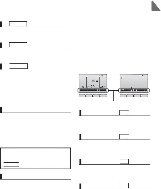
Function guide
7 Function button F1
Main display: Press to change the operation mode.
Main menu: Press to move the cursor down.
8 Function button F2
Main display: Press to decrease temperature. Main menu: Press to move the cursor up.
9 Function button F3
Main display: Press to increase temperature. Main menu: Press to go to the previous page.
0 Function button F4
Main display: Press to change the fan speed. Main menu: Press to go to the next page.
7

 Names and functions of controller components
Display
The main display can be displayed in two different modes: "Full" and "Basic." The factory setting is "Full." To switch to the "Basic" mode, change the setting on the Main display setting. (Refer to page 44.)
Full mode
* All icons are displayed for |
bcdef g h |
|
|
explanation. |
|
|
|
|
Fri |
3 |
7 |
6 |
|
|
i |
8 |
|
|
|
|
9 |
Room |
|
j |
|
|
0 |
Set temp. |
Auto |
|
|
Cool |
4 |
||
|
1 |
|
|
|
|
a |
Temp. |
Fan |
|
|
Mode |
|
||
|
|
k |
2 |
|
|
|
5 |
|
|
Basic mode
2


 Fri
Fri  3
3
Cool Set temp. |
Auto |
1 |
4 |
Mode |
Temp. |
Fan |
5
8
1Operation mode |
Page 14 |
Indoor unit operation mode appears here.
2Preset temperature |
Page 14 |
Preset temperature appears here.
3Clock
(See the Installation Manual.)
Current time appears here.
4Fan speed |
Page 15 |
Fan speed setting appears here.
5Button function guide
Functions of the corresponding buttons appear here.
6
Appears when the ON/OFF operation is centrally controlled.
7
Appears when the operation mode is centrally controlled.
8
Appears when the preset temperature is centrally controlled.
9
Appears when the filter reset function is centrally controlled.
0 |
Page 48 |
Indicates when filter needs maintenance.
|
b |
Page 34 |
|
Appears when the buttons are locked. |
|
|
c |
Page 40 |
|
||
Appears when the On/Off timer or Night setback function is enabled.
d |
Page 28 |
Appears when the Weekly timer is enabled.
e |
Page 36 |
Appears while the units are operated in the energy-save mode.
f |
Page 30 |
Appears while the outdoor units are operated in the silent mode.
g
Appears when the built-in thermistor on the remote controller is activated to monitor the room temperature (a).
appears when the thermistor on the indoor unit is activated to monitor the room
temperature.
|
h |
Page 20 |
|
Indicates the vane setting. |
|
|
i |
Page 21 |
|
||
|
Indicates the louver setting. |
|
|
j |
Page 21 |
|
||
|
Indicates the ventilation setting. |
|
aRoom temperature
(See the Installation Manual.)
Current room temperature appears here.
k |
Page 32 |
Appears when the preset temperature range is restricted.
Most settings (except ON/OFF, mode, fan speed, temperature) can be made from the Menu screen. (Refer to page 18.)
9
 Read before operating the controller
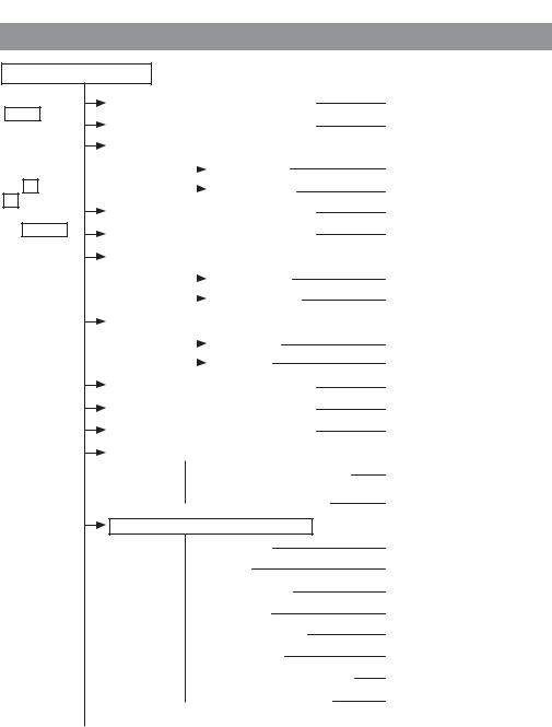
Menu structure
Main menu
Press the
MENU button.
Move the cursor to the desired item with
the F1 and F2 buttons, and press the SELECT button.
Vane•Louver•Vent. (Lossnay) |
Page 20 |
||
|
|
|
Page 22 |
High power |
|||
|
|
|
|
|
Timer |
|
|
|
|
On/Off timer |
Page 24 |
|
|
||
|
|
Auto-Off timer |
Page 26 |
|
|
||
|
|
|
Page 28 |
Weekly timer |
|||
|
|
|
Page 30 |
OU silent mode |
|||
|
|
|
|
Restriction |
|
||
|
|
Temp. range |
Page 32 |
|
|
||
|
|
Operation lock |
Page 34 |
|
|
||
|
|
|
|
Energy saving |
|
||
|
|
Auto return |
Page 36 |
|
|
||
|
|
Schedule |
Page 38 |
|
|
||
|
|
|
Page 40 |
Night setback |
|||
|
|
|
Page 48 |
Filter information |
|||
|
|
|
Page 50 |
Error information |
|||
|
|
|
|
Maintenance |
|
||
 Auto descending panel
 Manual vane angle
Initial setting
 Main/Sub
 Clock
Clock
 Main display
 Contrast
 Display details
 Auto mode
 Administrator password
  Language selection
Refer to the Instructions Manual that came with the automatic elevating panel.
Page 42
Refer to the Installation Manual.
Page 23
Page 44
Page 45
Refer to the Installation Manual. Refer to the Installation Manual. Refer to the Installation Manual.
Page 46
10
Service
 Test run
 Input maintenance info.
 Function setting
  Lossnay (City Multi only)
 Check
Check
 Self check
 Maintenance password
  Remote controller check
Refer to the indoor unit Installation Manual.
Refer to the indoor unit Installation Manual.
Refer to the Installation Manual. Refer to the Installation Manual.
Refer to the indoor unit Installation Manual.
Refer to the Installation Manual. Refer to the Installation Manual. Refer to the Installation Manual.
Not all functions are available on all models of indoor units.
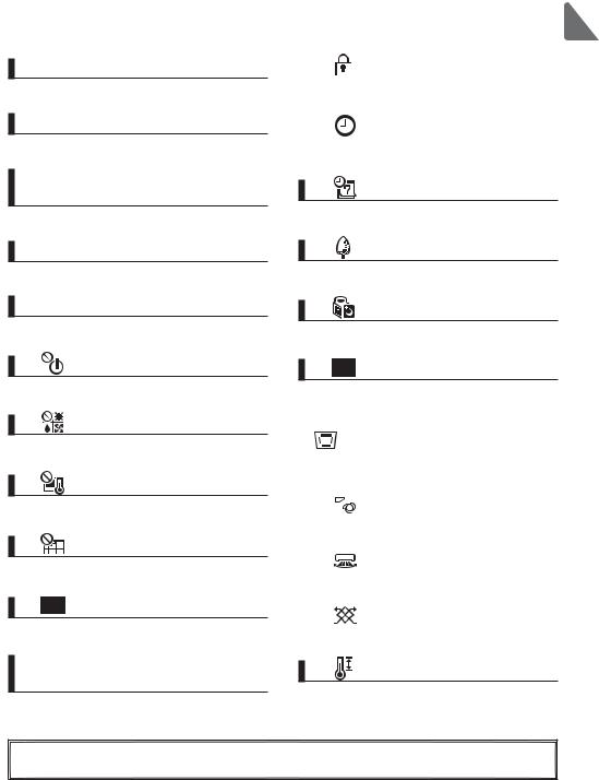
Icon explanations
|
Controller operation |
|
|
|
|
|
|
||||||||
|
|
|
|
|
|
|
|
|
|
|
|
|
|
The table below |
|
|
Timer |
|
|
|
|
|
|
|
|
P |
|
|
|
summarizes the square |
|
|
|
|
|
|
|
|
|
|
|
|
|
||||
|
|
|
|
|
|
|
|
|
|
|
|
||||
|
|
|
|
|
|
|
|
|
|
|
|
|
|
icons used in this manual. |
|
|
|
|
|
|
|
|
|
|
|
|
|||||
|
|
|
|
|
|
|
|||||||||
|
|
The administrator password must be entered on the password |
|
||||||||||||
|
P |
input screen to change settings. There is no settings that can skip |
Main |
||||||||||||
|
this process. |
|
|
|
|
|
|
|
|
|
|||||
|
|
|
|
|
Timer |
|
|
|
|
|
|
|
|
|
|
|
|
|
Enter administrator password |
|
|
|
|
|
|
|
|
||||
|
|
|
|
|
|
|
|
|
|
|
|||||
|
|
|
F1 |
: Press to move the cursor left. |
Indicates |
||||||||||
|
|
|
|
|
|
|
|
||||||||
|
|
|
|
|
|
|
|
|
: Press to move the cursor right. |
settings that |
|||||
|
|
|
|
|
|
|
|
F2 |
|||||||
|
|
|
|
|
|
|
|
|
: Press to decrease the value by 1. |
can be made |
|||||
|
|
|
|
|
|
|
|
F3 |
|||||||
|
|
|
Select: |
|
|
|
|
||||||||
|
|
|
|
|
|
|
|
: Press to increase the value by 1. |
only from the |
||||||
|
|
|
Cursor |
|
|
|
F4 |
||||||||
|
|
|
|
|
|
|
|
|
|
|
|
|
|
|
main remote |
|
|
|
F1 |
F2 |
F3 |
F4 |
*Changes cannot be made unless the |
controller. |
|||||||
|
|
|
correct password is entered. |
|
|||||||||||
|
|
|
|
|
|
|
|
|
|||||||
|
|
Indicates settings that can be |
|
|
Indicates settings that can be changed |
||||||||||
|
ON |
changed only while the units |
OFF |
only while the units are not in operation. |
|||||||||||
|
are in operation. |
|
|
|
|
|
|
|
|
||||||
|
|
|
|
|
|
||||||||||
|
|
Indicates settings that can be |
|
|
Indicates functions that are not available |
||||||||||
|
|
changed only while the units |
|
|
when the buttons are locked or the |
||||||||||
|
|
are operated in the Cool, |
|
|
system is centrally controlled. |
||||||||||
|
|
Heat, or Auto mode. |
|
|
|
|
|
|
|
|
|
|
|||
11
 Basic operations
Power ON/OFF
Button operation
ON
Press the ON/OFF button.
The ON/OFF lamp will light up in green, and the operation will start.
OFF
Press the ON/OFF button again.
The ON/OFF lamp will come off, and the operation will stop.
12
Operation status memory
|
Remote controller setting |
Operation mode |
Operation mode before the power was turned off |
Preset temperature |
Preset temperature before the power was turned off |
Fan speed |
Fan speed before the power was turned off |
Settable preset temperature range
Operation mode |
Preset temperature range |
Cool/Dry |
19 ~ 30 ºC (67 ~ 87 ºF) |
Heat |
17 ~ 28 ºC (63 ~ 83 ºF) |
Auto |
19 ~ 28 ºC (67 ~ 83 ºF) |
Fan/Ventilation |
Not settable |
The settable temperature range varies with the model of indoor units.
13

Operation mode, temperature, and fan speed settings ON
Button operation
Operation mode
|
|
|
|
Fri |
|
|
Room |
|
|
Cool |
|
Set temp. |
|
Auto |
Mode |
|
Temp. |
|
Fan |
|
|
Press the F1 button to go through the operation
modes in the order of "Cool, Dry, Fan, Auto, and Heat." Select the desired operation mode.
Cool |
|
Dry |
|
Fan |
|
|
|
|
|
F1 F2 F3 F4 |
Auto |
Heat |
•Operation modes that are not available to the connected indoor unit models will not appear on the display.
What the blinking mode icon means
The mode icon will blink when other indoor units in the same refrigerant system (connected to the same outdoor unit) are already operated in a different mode. In this case, the rest of the unit in the same group can only be operated in the same mode.
Preset temperature
|
|
|
|
Fri |
|
|
Room |
|
|
Cool |
|
Set temp. |
|
Auto |
Mode |
|
Temp. |
|
Fan |
|
|
Press the F2 button to decrease the preset
temperature by 1ºC (1ºF), and press the F3 button to increase.
•Refer to the table on page 13 for the settable temperature range for different operation modes. •Preset temperature range cannot be set for Fan/
Ventilation operation.
F1 F2 F3 F4
14

Fan speed
|
|
|
|
Fri |
|
|
Room |
|
|
Cool |
|
Set temp. |
|
Auto |
Mode |
|
Temp. |
|
Fan |
|
|
F1 F2 F3 F4
Press the F4 button to go through the fan speeds in the following order.

 Auto
Auto
•The available fan speeds depend on the models of connected indoor units.
•Fan speed can be changed even when the buttons are locked or when the system is centrally controlled.
15

 Navigating through the menu
Main menu list
Setting and display |
Setting details |
Reference |
|
items |
|
page |
|
Vane•Louver•Vent. |
Use to set the vane angle. |
20 |
|
(Lossnay) |
|
•Select a desired vane setting from five different settings. |
|
|
|
Use to turn ON/OFF the louver. |
|
|
|
•Select a desired setting from "ON" and "OFF." |
|
|
|
Use to set the amount of ventilation. |
|
|
|
•Select a desired setting from "Off," "Low," and "High." |
|
|
|
|
|
High power |
|
Use to reach the comfortable room temperature quickly. |
22 |
|
|
•Units can be operated in the High-power mode for up to 30 |
|
|
|
minutes. |
|
Timer |
On/Off |
Use to set the operation On/Off times. |
24 |
|
timer |
•Time can be set in 5-minute increments. |
|
|
|
* Clock setting is required. |
|
|
Auto-Off |
Use to set the Auto-Off time. |
26 |
|
timer |
•Time can be set to a value from 30 to 240 in 10-minute increments. |
|
Weekly timer |
Use to set the weekly operation On/Off times. |
28 |
|
|
|
•Up to eight operation patterns can be set for each day. |
|
|
|
* Clock setting is required. |
|
|
|
* Not valid when the On/Off timer is enabled. |
|
OU silent mode |
Use to set the time periods in which priority is given to quiet |
30 |
|
|
|
operation of outdoor units over temperature control. Set the |
|
|
|
Start/Stop times for each day of the week. |
|
|
|
•Select the desired silent level from "Normal," "Middle," and "Quiet." |
|
|
|
* Clock setting is required. |
|
Restriction |
Temp. |
Use to restrict the preset temperature range. |
32 |
|
range |
•Different temperature ranges can be set for different operation |
|
|
|
modes. |
|
|
Operation |
Use to lock selected functions. |
34 |
|
lock |
•The locked functions cannot be operated. |
|
Energy |
Auto |
Use to get the units to operate at the preset temperature after |
36 |
saving |
return |
performing energy-save operation for a specified time period. |
|
|
|
•Time can be set to a value from 30 and 120 in 10-minute |
|
|
|
increments. |
|
|
|
* This function will not be valid when the preset temperature ranges |
|
|
|
are restricted. |
|
|
Schedule |
Set the start/stop times to operate the units in the energy-save |
38 |
|
|
mode for each day of the week, and set the energy-saving rate. |
|
|
|
•Up to four energy-save operation patterns can be set for each day. |
|
|
|
•Time can be set in 5-minute increments. |
|
|
|
•Energy-saving rate can be set to a value from 0% and 50 to 90% in |
|
|
|
10% increments. |
|
|
|
* Clock setting is required. |
|
16
Setting and display |
Setting details |
Reference |
|
items |
|
page |
|
Night setback |
Use to make Night setback settings. |
40 |
|
|
|
•Select "Yes" to enable the setting, and "No" to disable the setting. |
|
|
|
The temperature range and the start/stop times can be set. |
|
|
|
* Clock setting is required. |
|
|
|
|
|
Filter information |
Use to check the filter status. |
48 |
|
|
|
•The filter sign can be reset. |
|
Error information |
Use to check error information when an error occurs. |
50 |
|
|
|
•Error code, error source, refrigerant address, unit model, |
|
|
|
manufacturing number, contact information (dealer's phone |
|
|
|
number) can be displayed. |
|
|
|
* The unit model, manufacturing number, and contact information |
|
|
|
need to be registered in advance to be displayed. |
|
Maintenance |
Manual vane |
Use to set the vane angle for each vane to a fixed position. |
42 |
|
angle |
|
|
Initial |
Clock |
Use to set the current time. |
23 |
setting |
Main |
Use to switch between "Full" and "Basic" modes for the Main |
44 |
|
display |
display. |
|
|
|
•The default setting is "Full." |
|
|
Contrast |
Use to adjust screen contrast. |
45 |
|
Language |
Use to select the desired language. |
46 |
|
selection |
|
|
Restrictions for the sub remote controller
Main |
Main menu |
 Vane·Louver·Vent. (Lossnay) High power
Timer Weekly timer
OU silent mode Main display: 
 Cursor
 Page
Page 
The following settings cannot be made from the sub remote controller. Make these settings from the main remote controller. "Main" is displayed in the title of the Main menu on the main remote controller.
•Timer
(On/Off timer, Auto-Off timer)
•Weekly timer
•OU silent mode
•Energy saving
(Auto return, Schedule)
•Night setback
•Maintenance
(Manual vane angle)
17
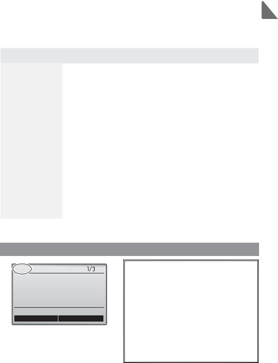
 Loading...