


Mitsubishi MUZ-GE25VA(H), MUZ-GE35VA(H), MUZ-GE42VA(H), MUZ-GE50VA(H), MUZ-GE60VA Service Manual
...Revision B:
SPLIT-TYPE AIR CONDITIONERS
•MUZ-GE60VA - E1 and MUZ-GE71VA - E1 have been added.
Please void OBH516 REVISED EDITION-A.
OUTDOOR UNIT
SERVICE MANUAL
HFC |
No. OBH516 |
utilized |
REVISED EDITION-B |
R410A |
|
Models
MUZ-GE25VA - E1 MUZ-GE25VAH - MUZ-GE35VA - E1 MUZ-GE35VAH - MUZ-GE42VA - E1 MUZ-GE42VAH -
E1
E1
E1
MUZ-GE50VA - E1 MUZ-GE50VAH - E1 MUZ-GE60VA - E1 MUZ-GE71VA - E1
Indoor unit service manual
MSZ-GE•VA Series (OBH515)
MSZ-CGE•VA Series (OBH523)
MUZ-GE25VA MUZ-GE35VA MUZ-GE42VA
CONTENTS
1.TECHNICAL CHANGES ··································· 3
2.PART NAMES AND FUNCTIONS····················· 4
3.SPECIFICATION················································ 5
4.NOISE CRITERIA CURVES ······························ 7
5.OUTLINES AND DIMENSIONS ························ 9
6.WIRING DIAGRAM···········································11
7.REFRIGERANT SYSTEM DIAGRAM ············· 18
8.PERFORMANCE CURVES ····························· 21
9.ACTUATOR CONTROL··································· 40
10.SERVICE FUNCTIONS···································· 41
11.TROUBLESHOOTING ····································· 41
12.DISASSEMBLY INSTRUCTIONS···················· 61
PARTS CATALOG (OBB516)
NOTE:
RoHS compliant products have <G> mark on the spec name plate.

Revision A:
• MUZ-GE42VA - E1 , MUZ-GE42VAH - E1 , MUZ-GE50VA - E1 and MUZ-GE50VAH - E1 have been added.
Revision B:
• MUZ-GE60VA - E1 and MUZ-GE71VA - E1 have been added.
2

1 
 TECHNICAL CHANGES
MUZ-GE25VA - E1 MUZ-GE35VA - E1 MUZ-GE42VA - E1 MUZ-GE50VA - E1 MUZ-GE60VA - E1 MUZ-GE71VA - E1
1. New model
MUZ-GE25VAH - E1 MUZ-GE35VAH - E1 MUZ-GE42VAH - E1 MUZ-GE50VAH - E1
3
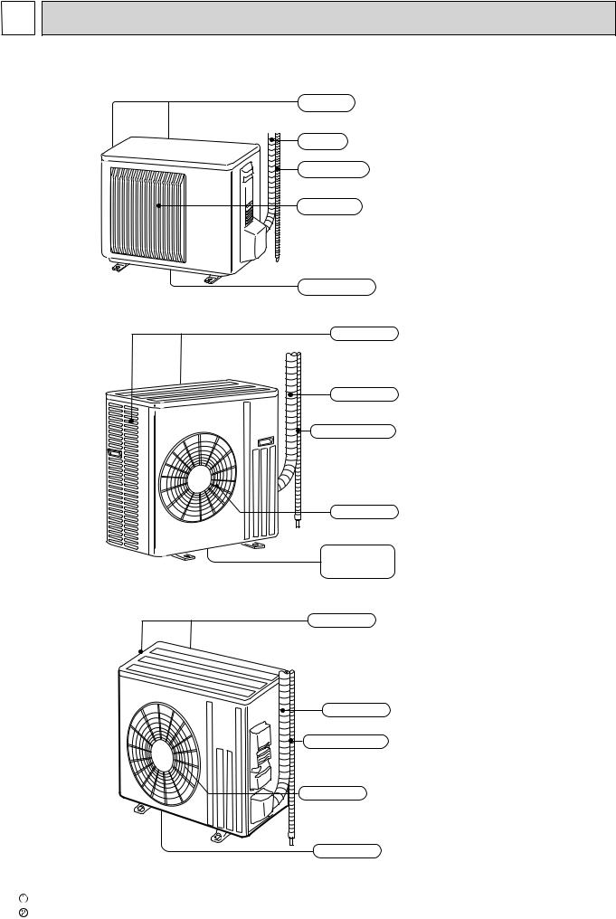
2 PART NAMES AND FUNCTIONS
MUZ-GE25VA MUZ-GE25VAH MUZ-GE35VA MUZ-GE35VAH MUZ-GE42VA MUZ-GE42VAH
Air inlet (back and side)
Piping
Drain hose
Air outlet
Drain outlet
MUZ-GE50VA MUZ-GE50VAH
Air inlet (back and side)
Piping
Drain hose
Air outlet
Drain outlet (GE50VA)
MUZ-GE60VA MUZ-GE71VA
Air inlet (back and side)
Piping
Drain hose
Air outlet
ACCESSORIES |
|
Drain outlet |
|
|||
|
|
|
|
|
|
|
|
Model |
|
MUZ-GE25/35/42VA |
MUZ-GE50VA |
|
MUZ-GE60/71VA |
|
Drain socket |
|
1 |
1 |
|
1 |
|
Drain cap |
|
- |
2 |
|
- |
4
3 
 SPECIFICATION
Outdoor model
Power supply
Capacity |
|
|
|
|
|
|
Cooling |
kW |
||
Rated frequency (Min.-Max.) |
|
|
|
|||||||
|
|
Heating |
||||||||
|
|
|
||||||||
Breaker Capacity |
|
|
|
|
|
Cooling |
A |
|||
data |
Power input |
|
1 (Total) |
|
|
W |
||||
|
|
|
Heating |
|||||||
|
|
|
|
|
|
|
|
|
||
Running current |
1 |
|
|
|
Cooling |
A |
||||
Electrical |
|
|
|
|||||||
Power factor |
1 (Total) |
|
|
Heating |
||||||
|
|
% |
||||||||
|
(Total) |
|
|
|
|
|
|
Heating |
|
|
|
|
|
|
|
|
|
|
|
Cooling |
|
|
Starting current |
1 (Total) |
|
|
|
A |
||||
|
|
|
||||||||
Coefficient of performance |
|
|
|
Cooling |
||||||
(COP) 1 (Total) |
Model |
|
|
|
Heating |
|||||
|
|
|
|
|
|
|
|
|||
Compressor |
|
Output |
|
|
|
Cooling |
W |
|||
|
Current |
1 |
|
|
A |
|||||
|
|
|
|
|
Heating |
|||||
|
|
|
|
|
|
|
|
|
|
|
|
|
|
Refrigeration |
|
oil (Model) |
cc |
||||
Fan motor |
|
Model |
|
|
|
Cooling |
|
|||
|
Current |
1 |
|
|
A |
|||||
|
|
|
|
|
Heating |
|||||
Dimensions W × |
|
H × D |
|
|
|
mm |
||||
|
|
|
|
|
||||||
Weight |
|
|
|
|
|
|
|
kg |
||
|
Dehumidification |
|
|
|
|
Cooling |
/h |
|||
|
|
|
|
Cooling |
|
|
High |
|
||
|
|
|
|
|
|
Med. |
|
|||
|
Air flow 1 |
|
|
|
|
|
|
|
Low |
m3/h |
|
|
|
Heating |
|
|
High |
||||
|
|
|
|
|
|
|||||
remarks |
|
|
|
|
|
Med. |
|
|||
Sound level |
|
|
1 |
|
|
|
|
Cooling |
dB(A) |
|
|
|
|
|
|
|
|
|
|
Low |
|
|
|
|
|
|
|
|
|
|
|
|
Special |
|
|
|
|
|
|
|
|
Heating |
|
|
|
|
Cooling |
|
|
High |
|
|||
|
|
|
|
|
|
|
||||
|
|
|
|
|
|
Med. |
|
|||
|
Fan speed |
|
|
|
|
|
|
|
Low |
rpm |
|
|
|
Heating |
|
|
High |
||||
|
|
|
|
|
|
|
||||
|
|
|
|
|
|
Med. |
|
|||
|
Fan speed |
|
regulator |
|
|
|
Low |
|
||
|
|
|
|
|
|
|
||||
|
Refrigerant filling capacity (R410A) |
kg |
||||||||
MUZ- |
MUZ- |
|
MUZ- |
MUZ- |
MUZ- |
|
MUZ- |
GE25VA |
GE35VA |
|
GE42VA |
GE50VA |
|
||
MUZ- |
MUZ- |
|
MUZ- |
MUZ- |
GE60VA |
|
GE71VA |
GE25VAH |
GE35VAH |
|
GE42VAH |
GE50VAH |
|
|
|
|
|
|
Single phase, 230 V, 50 Hz |
|
|
|
|
2.5 (1.1 - 3.5) |
3.5 (1.1 - 4.0) |
|
4.2 (0.9 - 4.8) |
5.0 (1.4 - 5.5) |
6.0 (1.5 - 7.5) |
|
7.1 (2.4 - 8.7) |
3.2 (1.3 - 4.5) |
4.0 (1.6 - 5.3) |
|
5.4 (1.4 - 6.0) |
5.8 (1.4 - 7.3) |
6.8 (2.0 - 9.3) |
|
8.1 (2.2 - 9.9) |
|
10 |
|
|
16 |
20 |
||
545 |
865 |
|
1,215 |
1,515 |
1,760 |
|
2,130 |
700 |
955 |
|
1,460 |
1,565 |
1,770 |
|
2,110 |
2.9 |
4.2 |
|
5.6 |
6.8 |
7.8 |
|
9.3 |
3.7 |
4.6 |
|
6.6 |
7.0 |
7.9 |
|
9.4 |
82 |
90 |
|
94 |
96 |
98 |
|
99 |
82 |
90 |
|
96 |
97 |
|
98 |
|
3.7 |
4.6 |
|
6.6 |
7.0 |
7.9 |
|
9.4 |
4.59 |
4.05 |
|
3.46 |
3.30 |
3.40 |
|
3.33 |
4.57 |
4.19 |
|
3.70 |
3.71 |
3.84 |
|
3.83 |
KNB073FFDHC |
KNB092FFAHC |
|
SNB130FGBHT |
SNB130FGBMT |
|
SNB172FEKMT |
|
550 |
650 |
|
|
900 |
|
|
1,200 |
2.44 |
3.56 |
|
4.99 |
6.09 |
6.59 |
|
8.00 |
3.20 |
4.06 |
|
5.98 |
6.32 |
6.44 |
|
8.07 |
320 |
(NEO22) |
|
450 |
(NEO22) |
350(FV50S) |
|
400(FV50S) |
RC0J50-DB |
|
RC0J50-EA |
RC0J60-AA |
|
|
-BC |
|
|
RC0J60 |
||||||
0.24 |
0.35 |
|
|
|
0.84 |
|
0.83 |
|
0.32 |
|
|||||
0.27 |
0.31 |
0.32 |
0.93 |
|
0.82 |
||
800 × 550 × 285 |
840 × 850 × 330 |
840 × 880 × 330 |
|||||
30 |
33 |
|
36 |
54 |
50 |
|
53 |
0.2 |
0.9 |
|
1.4 |
1.8 |
|
2.3 |
|
|
|
|
|
|
3,492 |
|
3,426 |
|
|
- |
|
|
|||
1,806 |
1,872 |
2,940 |
3,066 |
|
3,006 |
||
1,170 |
1,776 |
|
1,086 |
1,740 |
1,692 |
|
1,512 |
2,106 |
2,016 |
– |
2,952 |
|
2,892 |
||
1,806 |
1,776 |
2,940 |
2,952 |
|
2,892 |
||
1,452 |
1,386 |
2,142 |
2,226 |
|
2,280 |
||
|
|
|
50 |
54 |
|
|
|
47 |
|
55 |
|||||
48 |
|
51 |
56 |
55 |
|||
|
|
- |
|
950 |
|||
740 |
810 |
780 |
840 |
||||
490 |
770 |
|
490 |
480 |
|
450 |
|
860 |
870 |
– |
810 |
||||
740 |
770 |
780 |
810 |
||||
600 |
610 |
580 |
620 |
|
650 |
||
|
3 |
|
|
2 |
|
3 |
|
0.80 |
1.15 |
|
|
|
1.90 |
||
1.55 |
|
||||||
NOTE: Test conditions are based on ISO 5151. |
|
|
|
Cooling: Indoor |
Dry-bulb temperature 27°C |
Wet-bulb temperature |
19°C |
Outdoor |
Dry-bulb temperature 35°C |
|
|
Heating: Indoor |
Dry-bulb temperature 20°C |
|
|
Outdoor Dry-bulb temperature 7°C |
Wet-bulb temperature |
6°C |
|
Refrigerant piping length (one way): 5 m |
|
|
|
1 Measured under rated operating frequency. |
|
|
|
5

Specifications and rating conditions of main electric parts
Item |
Model |
MUZ- |
MUZ- |
|
MUZ- |
MUZ- |
|
MUZ- |
MUZ- |
MUZ- |
MUZ- |
|
MUZ- |
|
MUZ- |
|
GE25VA |
GE25VAH |
|
GE35VA |
GE35VAH |
|
GE42VA |
GE42VAH |
GE50VA |
GE50VAH |
|
GE60VA |
|
GE71VA |
|
Current |
(CT) |
|
|
|
|
20 |
A |
|
|
|
|
— |
|
||
transformer |
(CT761, CT781) |
|
|
|
|
15 A |
|
|
|
|
— |
|
|||
Smoothing |
(C61, C62, C63, |
|
|
|
|
620 μF 420 V |
|
|
|
|
560 μF 350 V |
||||
C81, C82, C83, |
|
|
|
|
|
|
|
|
|||||||
capacitor |
|
|
|
|
|
|
|
|
|||||||
CB1, CB2, CB3) |
|
|
|
|
|
|
|
|
|
|
|
|
|
|
|
|
|
|
|
|
|
|
|
|
|
|
|
|
|
|
|
Diode module |
(DB61) |
|
|
|
15 A 600 V |
|
|
25 A 600 V |
|
— |
|
||||
(DB65) |
|
|
|
|
25 A 600 V |
|
|
|
|
— |
|
||||
|
|
|
|
|
|
|
|
|
|
||||||
|
(F62) |
|
|
|
|
— |
|
|
|
|
|
T2.0AL250V |
|||
Fuse |
(F61) |
|
|
|
|
T20AL250V |
|
|
|
|
— |
|
|||
(F601, F701, F801, |
|
|
|
|
|
|
T3.15AL250V |
|
|
|
|
|
|
||
|
|
|
|
|
|
|
|
|
|
|
|
|
|||
|
F880, F901) |
|
|
|
|
|
|
|
|
|
|
|
|
||
|
|
|
|
|
|
|
|
|
|
|
|
|
|
|
|
Defrost heater |
(H) |
— |
230 V |
|
— |
230 V |
|
— |
230 V |
— |
230 V |
|
— |
|
|
130 W |
|
130 W |
|
130 W |
120 W |
|
|
||||||||
|
|
|
|
|
|
|
|
|
|
|
|
||||
Intelligent power |
(IC932) |
|
|
|
|
— |
|
|
|
|
|
5 A 600 V |
|||
module |
(IPM) |
|
15 A 600 V |
|
|
|
|
20 A 600 V |
|
|
|
||||
Expansion valve |
(LEV) |
|
|
|
|
|
|
12 V DC |
|
|
|
|
|
|
|
coil |
|
|
|
|
|
|
|
|
|
|
|
|
|||
|
|
|
|
|
|
|
|
|
|
|
|
|
|
|
|
Reactor |
(L, L61) |
18 mH |
|
|
|
|
23 mH |
|
|
|
340 μH |
||||
Power factor |
(PFC) |
|
|
|
|
— |
|
|
|
|
|
20 A 600 V |
|||
controller |
|
|
|
|
|
|
|
|
|
||||||
|
|
|
|
|
|
|
|
|
|
|
|
|
|
|
|
|
(R61) |
45 mΩ 5 W |
|
100 mΩ 5 W |
|
|
|
— |
|
|
|
||||
|
(1 element) |
|
(2 elements) |
|
|
|
|
|
|
||||||
|
|
|
|
|
|
|
|
|
|
|
|
||||
Current- |
(R61,R62) |
|
— |
|
|
|
|
180 mΩ 5 W |
|
|
— |
|
|||
|
|
|
|
|
(2 elements) |
|
|
|
|||||||
detecting |
|
|
|
|
|
|
|
|
|
|
|
|
|
|
|
(R825) |
|
|
|
|
25 mΩ 5 W |
|
|
|
|
— |
|
||||
resistor |
|
|
|
|
|
|
|
|
|
||||||
(R937, R938, |
|
|
|
430 mΩ 2 W |
|
|
|
— |
|
|
|
||||
|
|
|
|
|
|
|
|
|
|
||||||
|
R939) |
|
|
|
|
|
|
|
|
|
|||||
|
|
|
|
|
|
|
|
|
|
|
|
|
|
|
|
|
(R937A,R937B) |
|
|
|
— |
|
|
1.1 Ω 2 W |
|
— |
|
||||
Current-limiting |
(PTC64, |
|
|
|
|
|
|
33 Ω |
|
|
|
|
|
|
|
PTC thermistor |
PTC65) |
|
|
|
|
|
|
|
|
|
|
|
|
||
|
|
|
|
|
|
|
|
|
|
|
|
|
|
||
Terminal block |
(TB1, TB2) |
|
|
|
|
|
|
3 P |
|
|
|
|
|
|
|
|
(X63) |
|
|
|
|
3 A 250 V |
|
|
|
|
— |
|
|||
Relay |
(X64) |
|
|
|
|
|
|
20 A 250 V |
|
|
|
|
|
|
|
(X66) |
— |
3 A 250 V |
|
— |
3 A 250 V |
|
— |
3 A 250 V |
— |
3 A 250 V |
|
— |
|
||
|
(X601) |
|
|
|
|
— |
|
|
|
|
|
3 A 250 V |
|||
|
(X602) |
|
|
|
|
— |
|
|
|
|
|
3 A 250 V |
|||
R.V.coil |
(21S4) |
|
|
|
|
|
|
220 - 240 V AC |
|
|
|
|
|
|
|
Heater protector |
(26H) |
— |
Open 45°C |
|
— |
Open 45°C |
|
— |
Open 45°C |
— |
Open 45°C |
|
— |
|
|
IGBT |
(TR821) |
|
|
|
|
30 A 600 V |
|
|
|
|
— |
|
|||
6
, MUZ-GE35VA(H), MUZ-GE42VA(H), MUZ-GE50VA(H), MUZ-GE60VA Service Manual")
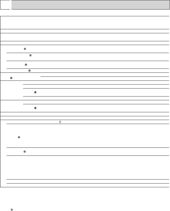
4 
 NOISE CRITERIA CURVES
MUZ-GE25VA MUZ-GE25VAH |
MUZ-GE35VA MUZ-GE35VAH |
FUNCTION SPL(dB(A)) |
LINE |
|
|
|
|
COOLING |
47 |
|
|
|
|
|
|
|
|
|
HEATING |
48 |
|
|
|
|
|
BAR |
90 |
|
|
|
|
|
|
|
BAR |
90 |
|
|
|
|
|
|
|
|
|
||
0.0002 MICRO |
80 |
|
|
|
|
|
|
|
0.0002 MICRO |
80 |
70 |
|
|
|
|
|
|
NC-70 |
70 |
||
re |
|
|
|
|
|
|
|
|
re |
|
OCTAVE BAND SOUND PRESSURE LEVEL, 0dB |
60 |
|
|
|
|
|
|
|
OCTAVE BAND SOUND PRESSURE LEVEL, dB |
60 |
|
|
|
|
|
|
|
NC-60 |
|
||
50 |
|
|
|
|
|
|
|
50 |
||
|
|
|
|
|
|
|
NC-50 |
|
||
40 |
|
|
|
|
|
|
|
40 |
||
|
|
|
|
|
|
|
NC-40 |
|
||
30 |
|
|
|
|
|
|
|
30 |
||
|
|
|
|
|
|
|
NC-30 |
|
||
20 |
|
|
|
|
|
|
|
20 |
||
|
|
|
|
NC-10 |
|
NC-20 |
|
|||
|
|
|
|
|
|
|
||||
10 |
|
|
|
|
|
|
|
10 |
||
|
125 |
250 |
500 |
1000 |
2000 |
4000 |
8000 |
|
||
|
63 |
|
|
|||||||
FUNCTION SPL(dB(A)) |
LINE |
|
|
|
COOLING |
47 |
|
|
|
|
|
|
HEATING |
48 |
|
|
|
|
|
|
|
|
|
|
NC-70 |
|
|
|
|
|
|
|
NC-60 |
|
|
|
|
|
|
|
NC-50 |
|
|
|
|
|
|
|
NC-40 |
|
|
|
|
|
|
|
NC-30 |
|
|
|
|
NC-10 |
|
NC-20 |
|
|
|
|
|
|
|
||
63 |
125 |
250 |
500 |
1000 |
2000 |
4000 |
8000 |
BAND CENTER FREQUENCIES, Hz |
BAND CENTER FREQUENCIES, Hz |
MUZ-GE42VA MUZ-GE42VAH |
MUZ-GE50VA MUZ-GE50VAH |
FUNCTION SPL(dB(A)) |
LINE |
|
|
|
|
COOLING |
50 |
|
|
|
|
|
|
|
|
|
HEATING |
51 |
|
|
|
|
|
BAR |
90 |
|
|
|
|
|
|
|
BAR |
90 |
|
|
|
|
|
|
|
|
|
||
0.0002 MICRO |
80 |
|
|
|
|
|
|
|
0.0002 MICRO |
80 |
70 |
|
|
|
|
|
|
NC-70 |
70 |
||
re |
|
|
|
|
|
|
|
|
re |
|
OCTAVE BAND SOUND PRESSURE LEVEL, 0dB |
60 |
|
|
|
|
|
|
|
OCTAVE BAND SOUND PRESSURE LEVEL, dB |
60 |
|
|
|
|
|
|
|
NC-60 |
|
||
50 |
|
|
|
|
|
|
|
50 |
||
|
|
|
|
|
|
|
NC-50 |
|
||
40 |
|
|
|
|
|
|
|
40 |
||
|
|
|
|
|
|
|
NC-40 |
|
||
30 |
|
|
|
|
|
|
|
30 |
||
|
|
|
|
|
|
|
NC-30 |
|
||
20 |
|
|
|
|
|
|
|
20 |
||
|
|
|
|
NC-10 |
|
NC-20 |
|
|||
|
|
|
|
|
|
|
||||
10 |
|
|
|
|
|
|
|
10 |
||
|
125 |
250 |
500 |
1000 |
2000 |
4000 |
8000 |
|
||
|
63 |
|
|
|||||||
FUNCTION SPL(dB(A)) |
LINE |
|
|
|
COOLING |
54 |
|
|
|
|
|
|
HEATING |
56 |
|
|
|
|
|
|
|
|
|
|
NC-70 |
|
|
|
|
|
|
|
NC-60 |
|
|
|
|
|
|
|
NC-50 |
|
|
|
|
|
|
|
NC-40 |
|
|
|
|
|
|
|
NC-30 |
|
|
|
|
NC-10 |
|
NC-20 |
|
|
|
|
|
|
|
||
63 |
125 |
250 |
500 |
1000 |
2000 |
4000 |
8000 |
BAND CENTER FREQUENCIES, Hz |
BAND CENTER FREQUENCIES, Hz |
7
|
|
MUZ-GE60VA |
MUZ-GE71VA |
FUNCTION SPL(dB(A)) |
LINE |
|
|
|
|
COOLING |
55 |
|
|
|
|
|
|
|
|
|
HEATING |
55 |
|
|
|
|
|
BAR |
90 |
|
|
|
|
|
|
|
BAR |
90 |
|
|
|
|
|
|
|
|
|
||
MICRO |
80 |
|
|
|
|
|
|
|
MICRO |
80 |
|
|
|
|
|
|
|
|
|
||
0.0002 |
70 |
|
|
|
|
|
|
NC-70 |
0.0002 |
70 |
|
|
|
|
|
|
|
|
|||
0dB re |
|
|
|
|
|
|
|
0dB re |
|
|
60 |
|
|
|
|
|
|
|
60 |
||
LEVEL, |
|
|
|
|
|
|
|
LEVEL, |
||
|
|
|
|
|
|
|
NC-60 |
|
||
50 |
|
|
|
|
|
|
|
50 |
||
PRESSURE |
|
|
|
|
|
|
|
PRESSURE |
||
|
|
|
|
|
|
|
NC-50 |
|
||
40 |
|
|
|
|
|
|
|
40 |
||
|
|
|
|
|
|
|
NC-40 |
|
||
SOUND |
|
|
|
|
|
|
|
SOUND |
|
|
30 |
|
|
|
|
|
|
|
30 |
||
|
|
|
|
|
|
|
NC-30 |
|
||
BAND |
|
|
|
|
|
|
|
BAND |
|
|
20 |
|
|
|
|
|
|
|
20 |
||
OCTAVE |
|
|
|
|
|
|
|
OCTAVE |
||
|
|
|
|
NC-10 |
|
NC-20 |
|
|||
|
|
|
|
|
|
|
||||
10 |
|
|
|
|
|
|
|
10 |
||
|
125 |
250 |
500 |
1000 |
2000 |
4000 |
8000 |
|
||
|
63 |
|
|
|||||||
FUNCTION SPL(dB(A)) |
LINE |
|
|
|
COOLING |
55 |
|
|
|
|
|
|
HEATING |
55 |
|
|
|
|
|
|
|
|
|
|
NC-70 |
|
|
|
|
|
|
|
NC-60 |
|
|
|
|
|
|
|
NC-50 |
|
|
|
|
|
|
|
NC-40 |
|
|
|
|
|
|
|
NC-30 |
|
|
|
|
NC-10 |
|
NC-20 |
|
|
|
|
|
|
|
||
63 |
125 |
250 |
500 |
1000 |
2000 |
4000 |
8000 |
BAND CENTER FREQUENCIES, Hz |
BAND CENTER FREQUENCIES, Hz |
Test conditions
Cooling: Dry-bulb temperature 35°C
Heating: Dry-bulb temperature 7°C Wet-bulb temperature 6°C
OUTDOOR UNIT
1 m MICROPHONE
8
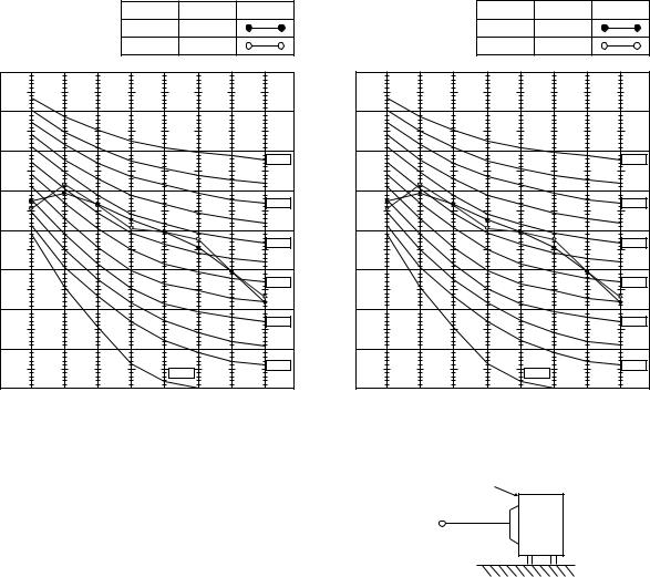
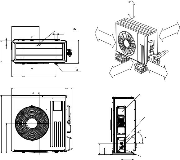
5 OUTLINES AND DIMENSIONS
MUZ-GE25VA MUZ-GE25VAH MUZ-GE35VA MUZ-GE35VAH MUZ-GE42VA MUZ-GE42VAH
Unit: mm
REQUIRED SPACE
100 mm or more
344.5 |
285 |
400 Air in
44
Air in
2 holes 10 X 21
Air out
22.3
Drain hole ø42 (MUZ-GE25/35/42VA) Drain hole ø33 (MUZ-GE25/35/42VAH)
Bolt pitch for installation 304~325
40 |
17.5 |
|
23
100 |
mm |
|
|
|
or |
|
more |
200 mm or more
Service panel
ormore mm 100
350 |
m |
|
m |
|
or |
|
more |
Handle
550
280 |
10 |
|
164.5 |
|
|
150 |
69 |
99.5 |
170.5 |
|
|
|
||
|
|
|
|
|
|
302.5 |
|
|
Service port |
|
500 Bolt pitch for installation |
|
|
|
|
800 |
|
|
|
Liquid refrigerant pipe joint Refrigerant pipe (flared) ø6.35
35 |
43 |
Gas refrigerant pipe joint Refrigerant pipe (flared) ø9.52
MUZ-GE50VA MUZ-GE50VAH
330
850
515
299
66
Air in
51 34
Air in 
170 Air out 500
840
121
430
500 mm or more
REQUIRED SPACE
Drain holes ø33(MUZ-GE50VA)
40 |
|
|
|
100 mm or more |
|||
360 |
100 |
mm |
|
|
|
|
|
|
|
|
|
|
|
|
|
|
|
or |
|
|
|
|
|
|
|
mo |
|
|
|
|
|
|
|
|
re |
|
|
|
|
4 holes 10 × 21 |
|
|
|
350 |
|
|
|
80 |
|
|
|
mm |
or |
|
|
|
|
500 mm or more |
|
|
more |
||
|
|
|
|
|
|||
|
|
|
|
|
|
||
|
|
|
|
|
|
|
|
|
|
|
|
Service panel |
|
|
|
|
|
|
|
Liquid refrigerant |
|||
|
|
|
|
pipe joint |
|
|
|
|
|
|
|
Refrigerant pipe |
|||
|
|
|
|
(flared) ø6.35 |
|
|
|
|
|
|
|
30° |
|
|
|
|
|
155 90 |
35° |
|
|
|
|
|
|
Gas refrigerant |
|
||||
|
|
|
|
pipe joint |
|
|
|
|
|
|
|
Refrigerant pipe |
|
||
|
|
|
198 |
(flared) ø12.7 |
|
|
|
9
|
|
MUZ-GE60VA MUZ-GE71VA |
Unit: mm |
417.5
Air in
330 |
50 |
Air out
175 500
840
109
880
452
REQUIRED SPACE
500 mm or more
Drain hole |
42 |
|
|
|
|
|
40 |
|
|
|
|
|
|
|
|
100 |
mm |
|
|
100 mm or more |
|
|
|
|
|
||
|
|
|
|
|
|
|
|
|
|
or |
|
|
|
|
360 |
|
more |
|
|
|
2-holes 10 21 |
|
|
350 |
|
|
|
|
|
|
|
mm |
|
|
|
|
|
|
|
|
|
|
|
|
|
|
or |
|
|
|
|
500 mm or more |
|
|
more |
|
|
|
|
|
|
|
81 |
|
|
|
|
|
|
|
|
|
|
Service panel |
|
|
Liquid refrigerant pipe joint Refrigerant pipe
(flared) Ø 6.35 (MUZ-GE60VA) Ø 9.52 (MUZ-GE71VA)
35
44
164.5 |
99.5 |
Gas refrigerant 195 pipe joint
Refrigerant pipe (flared) Ø 15.88
10
6 
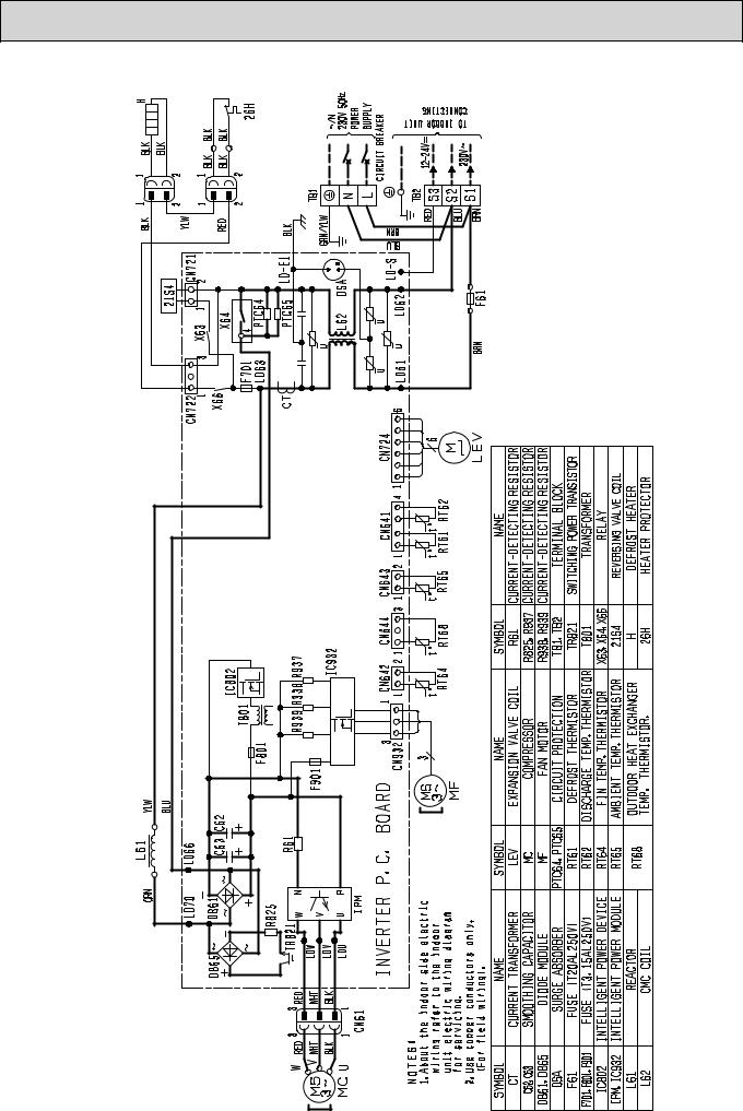
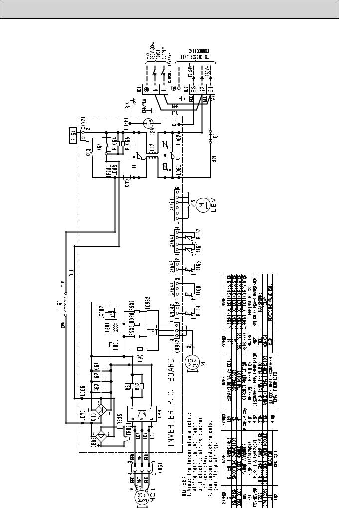
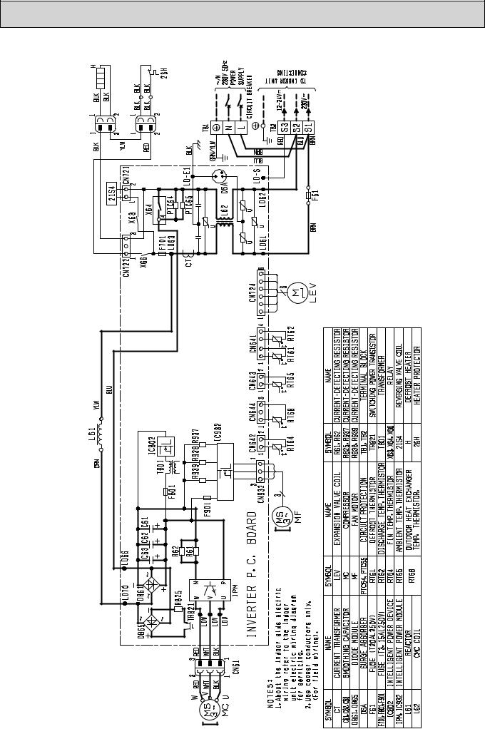
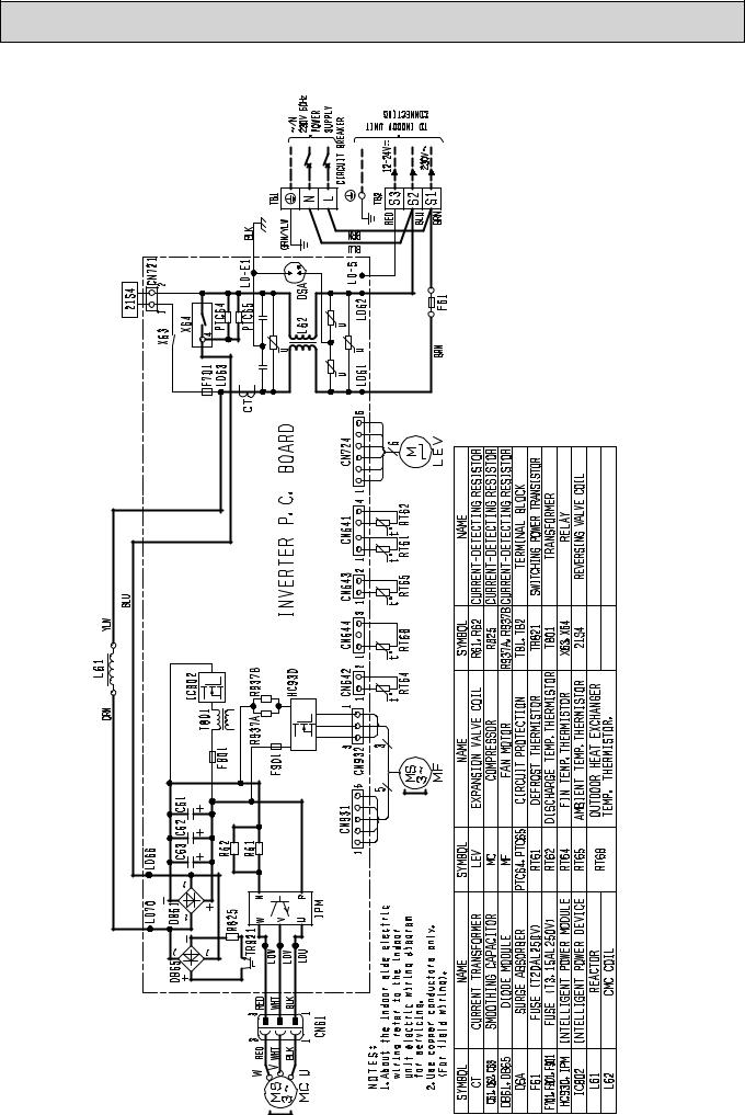
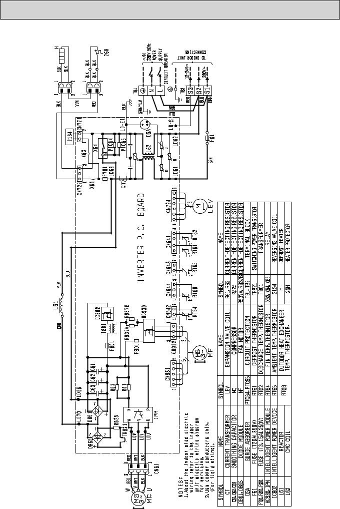
 WIRING DIAGRAM
MUZ-GE25VA MUZ-GE35VA
11
MUZ-GE25VAH MUZ-GE35VAH
12
MUZ-GE42VA
13
MUZ-GE42VAH
14
MUZ-GE50VA
15
MUZ-GE50VAH
16
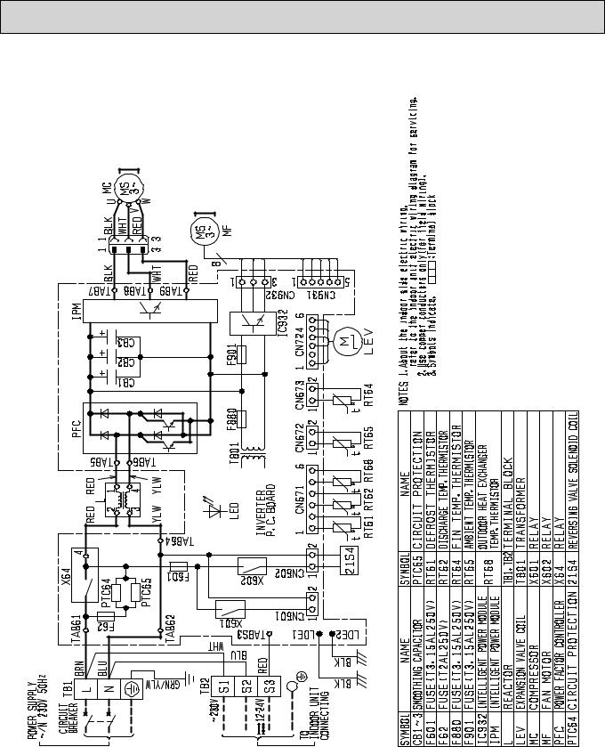
MUZ-GE60VA MUZ-GE71VA
17
7 
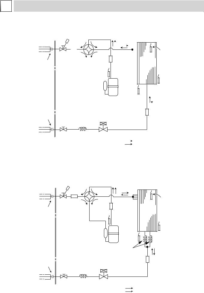
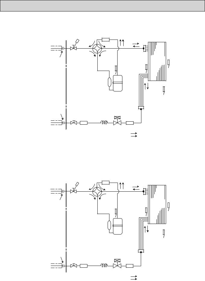
 REFRIGERANT SYSTEM DIAGRAM
MUZ-GE25VA MUZ-GE25VAH |
|
|
|
|
|
|
|
|
|
|
|
|
|
|
Unit: mm |
|||||
Refrigerant pipe |
ø9.52 |
|
|
4-way valve |
|
|
|
|
|
|
|
|
|
|
|
|
||||
(with heat insulator) |
|
|
|
|
|
|
|
|
|
|
|
|
|
|
||||||
|
|
|
|
|
|
|
|
|
|
|
|
|
|
|
|
|
|
|
||
|
|
Muffler |
|
|
|
|
|
|
|
|
|
|
|
|
|
|
Outdoor heat |
|||
|
|
|
|
|
|
|
|
|
|
|
|
|
|
|
|
|
|
|
|
|
|
|
|
|
|
|
|
|
|
|
|
|
|
|
|
|
|
|
|
|
|
|
|
Stop valve |
|
|
|
|
|
|
|
|
|
|
|
|
|
|
|
exchanger |
||
|
|
|
|
|
|
|
|
|
|
|
|
|
|
|
|
|
||||
|
|
|
|
|
|
|
|
|
|
|
|
|
|
|
|
|
temperature |
|||
|
|
(with service port) |
|
|
|
|
Muffler |
|
Outdoor |
thermistor |
||||||||||
Flared connection |
|
|
|
|
Discharge |
|
|
|
|
|
|
|
|
heat |
RT68 |
|||||
|
|
|
|
|
|
|
|
|
|
|
|
|||||||||
|
|
|
|
|
|
temperature |
|
|
|
|
|
|
|
exchanger |
|
|||||
|
|
|
|
|
|
thermistor |
|
|
|
|
|
|
|
|
|
|
|
|
||
|
|
|
|
|
|
RT62 |
Compressor |
|
|
|
|
|
Ambient |
|||||||
|
|
|
|
|
|
|
|
|
|
|
|
|
|
|||||||
|
|
|
|
|
|
|
|
|
|
|
|
|
|
|
|
|
|
|
|
temperature |
|
|
|
|
|
|
|
|
|
|
|
|
|
|
|
|
|
|
|
|
thermistor |
|
|
|
|
|
|
|
|
|
|
|
|
|
|
|
|
|
|
|
|
|
|
|
|
|
|
|
|
|
|
|
|
Defrost |
|
|
|
|
|
RT65 |
|||
|
|
|
|
|
|
|
|
|
|
|
|
|
|
|
|
|
||||
|
|
|
|
|
|
|
|
|
|
|
thermistor |
|
||||||||
|
|
|
|
|
|
|
|
|
|
|
RT61 |
|
|
|
|
|
|
|||
|
|
|
|
|
|
|
|
|
|
|
|
|
|
|
|
|
|
|
|
|
|
|
|
|
|
|
|
|
|
|
|
|
|
|
|
|
|
|
Strainer |
||
|
|
|
|
|
|
|
|
|
|
|
|
|
|
|
|
|
|
|||
Flared connection |
|
|
|
|
|
|
|
|
|
|
|
|
|
|
|
#100 |
|
|||
Capillary tube |
LEV |
|
|
|
|
|
|
|
|
|
R.V. coil |
|||||||||
|
|
|
|
|
|
|
|
|
|
|
||||||||||
|
|
ø3.0×ø2.0×240 |
|
|
|
|
|
|
|
|
|
|
|
|||||||
|
|
|
|
|
|
|
|
|
|
|
|
|
|
|
|
|
|
heating ON |
||
|
|
Stop valve |
|
|
|
|
|
|
|
|
|
|
|
|
cooling OFF |
|||||
|
|
|
|
|
|
|
|
|
|
|
|
|
|
|
|
|
||||
Refrigerant pipe |
ø6.35 (with strainar) |
|
|
|
|
|
|
|
|
|
Refrigerant flow in cooling |
|||||||||
|
|
|
|
|
|
|
|
|
||||||||||||
(with heat insulator) |
|
|
|
|
|
|
|
|
|
|
|
|
|
Refrigerant flow in heating |
||||||
MUZ-GE35VA MUZ-GE35VAH MUZ-GE42VA MUZ-GE42VAH
Unit: mm
Refrigerant pipe ø9.52 |
4-way valve |
|
|
|
|
(with heat insulator) |
|
|
|
||
|
|
|
|
|
|
|
Muffler |
|
|
|
Outdoor heat |
|
|
|
|
|
|
|
Stop valve |
|
|
|
exchanger |
|
|
|
|
temperature |
|
|
(with service port) |
|
|
|
|
Flared connection |
|
Muffler |
Outdoor |
thermistor |
|
Discharge |
|
heat |
RT68 |
||
|
temperature |
exchanger |
|
||
|
thermistor |
|
|
|
|
|
RT62 |
|
Compressor |
|
Ambient |
|
|
|
|
||
|
|
|
|
|
temperature |
|
|
|
|
|
thermistor |
|
|
|
Defrost |
|
RT65 |
|
|
|
|
|
|
|
|
|
thermistor |
|
|
|
|
|
RT61 |
|
|
|
|
|
Capillary tube |
|
|
|
|
|
ø3.0×ø1.8×600(×2) |
|
|
|
|
|
|
Strainer |
|
Flared connection |
|
LEV |
|
#100 |
|
Capillary tube |
|
|
|
||
|
|
R.V. coil |
|||
|
ø3.0×ø2.0×240 |
|
|
||
|
|
|
|
heating ON |
|
|
Stop valve |
|
|
cooling OFF |
|
|
|
|
|
|
|
Refrigerant pipe ø6.35 |
(with strainar) |
|
|
Refrigerant flow in cooling |
|
(with heat insulator) |
|
|
|
Refrigerant flow in heating |
|
18
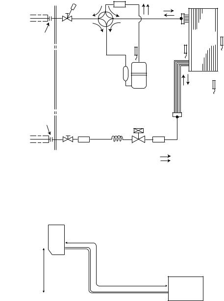
MUZ-GE50VA MUZ-GE50VAH |
|
|
|
Unit: mm |
Refrigerant pipe ø12.7 |
|
Muffler |
|
|
4-way valve |
#100 |
|
|
|
(with heat insulator) |
|
|
||
|
|
|
|
|
|
Stop valve |
|
|
|
Flared connection |
(with service port) |
Discharge |
Outdoor |
|
|
heat |
Ambient |
||
|
|
temperature |
exchanger |
temperature |
|
|
thermistor |
Defrost |
thermistor |
|
|
RT62 |
thermistor |
RT65 |
|
|
|
RT61 |
|
|
Compressor |
Outdoor heat |
|
|
|
||
|
|
exchanger |
|
|
|
temperature |
|
|
|
thermistor |
|
Flared connection |
|
RT68 |
|
LEV Strainer |
|
||
Receiver |
R.V. coil |
||
#100 |
|||
|
|
heating ON |
|
Stop valve |
Capillary tube |
cooling OFF |
|
Refrigerant pipe ø6.35 (with strainar) |
ø3.6×ø2.4×50 |
Refrigerant flow in cooling |
|
(with heat insulator) |
|
Refrigerant flow in heating |
MUZ-GE60VA
Refrigerant pipe ø15.88 |
|
Muffler |
|
4-way valve |
#100 |
||
(with heat insulator) |
|||
|
|
Stop valve |
|
|
|
|
(with service port) |
|
|
Outdoor |
|
Flared connection |
Discharge |
|
heat |
Ambient |
|
temperature |
Defrost |
exchanger |
temperature |
|
thermistor |
|
thermistor |
|
|
RT62 |
thermistor |
|
RT65 |
|
|
RT61 |
|
|
|
Compressor |
Outdoor heat |
|
|
|
|
|
|
|
|
|
|
exchanger |
|
|
|
|
temperature |
|
|
|
|
thermistor |
|
Flared connection |
|
|
RT68 |
|
LEV |
Strainer |
|
|
|
Strainer |
R.V. coil |
|
||
#100 |
|
#100 |
|
|
|
|
|
heating ON |
|
Stop valve |
Capillary tube |
|
cooling OFF |
|
Refrigerant pipe ø6.35 |
ø4.0×ø2.4×100 |
Refrigerant flow in cooling |
||
|
||||
(with heat insulator) |
|
Refrigerant flow in heating |
||
19
|
|
|
|
MUZ-GE71VA |
|
Unit: mm |
|
Refrigerant pipe ø15.88 |
|
Muffler |
|
4-way valve |
#100 |
||
(with heat insulator) |
|||
|
|
Stop valve |
|
|
|
|
(with service port) |
|
|
Outdoor |
|
Flared connection |
Discharge |
|
heat |
Ambient |
|
temperature |
Defrost |
exchanger |
temperature |
|
thermistor |
|
thermistor |
|
|
RT62 |
thermistor |
|
RT65 |
|
|
RT61 |
|
|
|
Compressor |
Outdoor heat |
|
|
|
|
|
|
|
|
|
|
exchanger |
|
|
|
|
temperature |
|
|
|
|
thermistor |
|
Flared connection |
|
|
RT68 |
|
LEV |
Strainer |
|
|
|
Strainer |
R.V. coil |
|
||
#100 |
|
#100 |
|
|
|
|
|
heating ON |
|
Stop valve |
Capillary tube |
|
cooling OFF |
|
|
|
|
||
Refrigerant pipe ø9.52 |
ø4.0×ø2.4×100 |
Refrigerant flow in cooling |
||
|
||||
(with heat insulator) |
|
Refrigerant flow in heating |
||
MAX. REFRIGERANT PIPING LENGTH and MAX. HEIGHT DIFFERENCE
|
|
|
|
|
|
|
|
|
Refrigerant piping: m |
|
|
|
|
|
|
|
Piping size O.D: mm |
|
||||||||||||||
|
|
|
|
Max. Length A |
|
|
|
Max. Height difference B |
|
|
Gas |
|
|
|
|
Liquid |
|
|||||||||||||||
MUZ-GE25/35/42 |
|
|
20 |
|
|
|
|
|
|
|
|
|
12 |
|
|
|
|
9.52 |
|
|
|
|
|
6.35 |
|
|||||||
MUZ-GE50 |
|
|
|
30 |
|
|
|
|
|
|
|
|
|
15 |
|
|
|
|
12.7 |
|
|
|
|
|
|
|||||||
MUZ-GE60 |
|
|
|
|
|
|
|
|
|
|
|
|
|
|
|
15.88 |
|
|
|
|
|
|
|
|
||||||||
MUZ-GE71 |
|
|
|
|
|
|
|
|
|
|
|
|
|
|
|
|
|
|
|
|
|
|
|
|
|
9.52 |
|
|||||
|
|
|
|
|
|
|
|
|
|
|
|
|
|
|
|
|
|
|
|
|
|
|
|
|
|
|
|
|
||||
|
|
|
|
|
Indoor |
|
|
|
|
|
|
|
|
|
|
|
|
|
|
|
|
|
|
|
|
|
|
|
|
|
||
|
|
|
|
|
unit |
|
|
|
|
|
|
|
|
|
|
|
|
|
|
|
|
|
|
|
|
|
|
|
|
|
||
|
|
|
|
|
|
|
|
|
|
|
|
|
|
|
|
|
|
|
|
|
|
|
|
|
|
|
|
|
|
|
|
|
|
|
|
|
|
Max. Height |
|
|
|
|
|
|
|
|
|
|
|
|
|
|
|
|
|
|
|
|
|
|
|||||
|
|
|
|
|
difference |
|
|
|
|
|
|
|
|
|
|
|
|
|
|
|
|
|
|
|
|
|
|
|||||
|
|
|
|
|
|
B |
|
|
|
|
|
|
|
|
|
|
|
|
|
|
|
|
|
|
|
|
|
|
|
|
|
|
|
|
|
|
|
|
|
|
|
|
|
|
|
|
|
Max. Length |
|
|
|
|
|
|
|
|
|
|
|
|
|
|
|||
|
|
|
|
|
|
|
|
|
|
|
|
|
|
|
A |
|
|
|
|
|
|
|
|
|
|
|
|
|
|
|
|
|
|
|
|
|
|
|
|
|
|
|
|
|
|
|
|
|
|
|
|
|
Outdoor unit |
|
|
|
|
|
|
|
|
|
|
||
|
|
|
|
|
|
|
|
|
|
|
|
|
|
|
|
|
|
|
|
|
|
|
|
|
|
|
||||||
ADDITIONAL REFRIGERANT CHARGE (R410A: g) |
|
|
|
|
|
|
|
|
|
|
|
|
|
|||||||||||||||||||
Model |
|
Outdoor unit |
|
|
|
|
|
|
|
|
|
|
Refrigerant piping length (one way) |
|
|
|
|
|||||||||||||||
|
precharged |
|
5 m |
|
|
6 m |
|
7 m |
|
8 m |
9 m |
10 m |
11 m |
|
12 m |
13 m |
|
14 m |
|
15 m |
20 m |
|||||||||||
|
|
|
|
|
|
|
|
|
|
|
||||||||||||||||||||||
MUZ-GE25 |
|
800 |
|
|
|
0 |
|
0 |
|
0 |
|
30 |
60 |
90 |
120 |
|
150 |
180 |
|
|
210 |
|
240 |
390 |
||||||||
MUZ-GE35/42 |
|
1,150 |
|
|
|
|
|
|
|
|
|
|||||||||||||||||||||
|
|
|
|
|
|
|
|
|
|
|
|
|
|
|
|
|
|
|
|
|
|
|
|
|
|
|
||||||
Calculation: X g = 30 g/m × (Refrigerant piping length (m) - 7) |
|
|
|
|
|
|
|
|
|
|
|
|
|
|
|
|
||||||||||||||||
Model |
|
Outdoor unit |
|
|
|
|
|
|
|
|
|
|
|
|
Refrigerant piping length (one way) |
|
|
|
|
|
|
|
||||||||||
|
precharged |
|
|
|
7 m |
|
|
|
10 m |
|
|
15 m |
|
|
20 m |
|
25 m |
|
|
30 m |
||||||||||||
|
|
|
|
|
|
|
|
|
|
|
|
|
|
|
||||||||||||||||||
MUZ-GE50 |
|
1,550 |
|
|
|
|
0 |
|
|
|
|
60 |
|
|
|
160 |
|
|
260 |
|
|
|
360 |
|
460 |
|||||||
Calculation: X g = 20 g/m × (Refrigerant piping length (m) – 7) |
|
|
|
|
|
|
|
|
|
|
|
|
|
|
|
|
||||||||||||||||
Model |
|
Outdoor unit |
|
|
|
|
|
|
|
|
|
|
|
|
Refrigerant piping length (one way) |
|
|
|
|
|
|
|
||||||||||
|
precharged |
|
|
|
7 m |
|
|
|
10 m |
|
|
15 m |
|
|
20 m |
|
25 m |
|
|
30 m |
||||||||||||
|
|
|
|
|
|
|
|
|
|
|
|
|
|
|
||||||||||||||||||
MUZ-GE60 |
|
1,550 |
|
|
|
|
0 |
|
|
|
|
0 |
|
|
|
100 |
|
|
200 |
|
|
|
300 |
|
400 |
|||||||
Calculation: X g = 20 g/m × (Refrigerant piping length (m) – 10) |
|
|
|
|
|
|
|
|
|
|
|
|
|
|
|
|
||||||||||||||||
|
|
|
|
|
|
|
|
|
|
|
|
|
|
|
|
|
|
|
|
|
|
|
||||||||||
Model |
|
Outdoor unit |
|
|
|
|
|
|
|
|
|
|
|
|
Refrigerant piping length (one way) |
|
|
|
|
|
|
|
||||||||||
|
precharged |
|
|
|
7 m |
|
|
|
10 m |
|
|
15 m |
|
|
20 m |
|
25 m |
|
|
30 m |
||||||||||||
|
|
|
|
|
|
|
|
|
|
|
|
|
|
|
||||||||||||||||||
MUZ-GE71 |
|
1,900 |
|
|
|
|
0 |
|
|
|
|
0 |
|
|
|
275 |
|
|
550 |
|
|
|
825 |
|
1,100 |
|||||||
Calculation: X g = 55 g/m × (Refrigerant piping length (m) – 10)
NOTE: Refrigerant piping exceeding 7 m requires additional refrigerant charge according to the calculation.
20
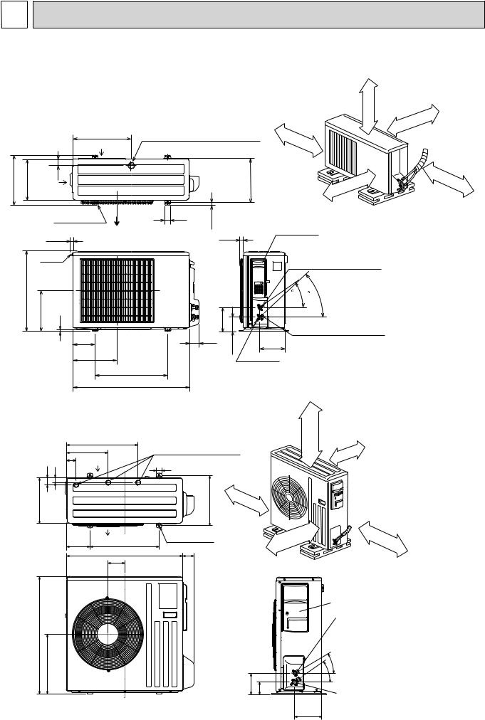
8 
 PERFORMANCE CURVES
MUZ-GE25VA MUZ-GE25VAH MUZ-GE35VA MUZ-GE35VAH MUZ-GE42VA MUZ-GE42VAH MUZ-GE50VA MUZ-GE50VAH MUZ-GE60VA MUZ-GE71VA
The standard specifications apply only to the operation of the air conditioner under normal conditions. Since operating conditions vary according to the areas where these units are installed, the following information has been provided to clarify the operating characteristics of the air conditioner under the conditions indicated by the performance curve.
(1)GUARANTEED VOLTAGE
198 ~ 264 V, 50 Hz
(2)AIR FLOW
Air flow should be set at MAX. |
|
|
|
||
(3) MAIN READINGS |
|
} |
|
||
(1) |
Indoor intake air wet-bulb temperature: |
°C [WB] |
|
||
(2) |
Indoor outlet air wet-bulb temperature: |
°C [WB] |
Cooling |
||
(3) |
Outdoor intake air dry-bulb temperature: |
°C [DB] |
|||
|
|||||
(4) Total input: |
W |
|
|||
(5) |
Indoor intake air dry-bulb temperature: |
°C [DB] |
} |
|
|
(6) |
Outdoor intake air wet-bulb temperature: |
°C [WB] |
Heating |
||
(7) Total input: |
W |
|
|||
Indoor air wet/dry-bulb temperature difference on the left side of the following chart shows the difference between the indoor intake air wet/dry-bulb temperature and the indoor outlet air wet/dry-bulb temperature for your reference at service.
How to measure the indoor air wet-bulb / dry-bulb temperature difference
1.Attach at least 2 sets of wet and dry-bulb thermometers to the indoor air intake as shown in the figure, and at least 2 sets of wet and dry-bulb thermometers to the indoor air outlet. The thermometers must be attached to the position where air speed is high.
2.Attach at least 2 sets of wet and dry-bulb thermometers to the outdoor air intake. Cover the thermometers to prevent direct rays of the sun.
3.Check that the air filter is cleaned.
4.Open windows and doors of room.
5.Press the EMERGENCY OPERATION switch once (twice) to start the EMERGENCY COOL (HEAT) MODE.
6.When system stabilizes after more than 15 minutes, measure temperature and take an average temperature.
7.10 minutes later, measure temperature again and check that the temperature does not change.
INDOOR UNIT |
|
OUTDOOR UNIT |
|
||||||||||||||||||||||||
|
|
|
|
|
|
|
|
|
|
|
|
|
|
|
|
|
|
|
|
|
|
|
|
|
|
|
|
|
|
|
|
|
|
|
|
|
|
|
|
|
|
|
|
|
|
|
|
|
|
|
|
|
|
|
|
|
|
|
|
|
|
|
|
|
|
|
|
|
|
|
|
|
|
|
|
|
|
|
|
|
|
|
|
|
|
|
|
|
|
|
|
|
|
|
|
|
|
|
|
|
|
|
|
|
|
|
|
|
|
|
|
|
|
|
|
|
|
|
|
|
|
|
|
|
|
|
|
|
|
|
|
|
|
|
|
|
|
|
|
|
|
|
|
|
|
|
|
|
|
|
|
|
|
|
|
|
|
|
|
|
|
|
|
|
|
|
|
|
|
|
|
|
|
|
|
|
|
|
|
|
|
|
|
|
|
|
|
|
|
|
|
|
|
|
|
|
|
|
|
|
|
|
|
|
|
|
|
|
|
|
|
|
|
|
|
|
|
|
|
|
|
|
|
|
|
|
|
|
|
|
|
|
|
|
|
|
|
|
|
|
|
|
|
|
|
|
|
|
|
|
|
|
|
|
|
|
|
|
|
|
|
|
|
|
|
|
|
|
|
|
|
|
|
|
|
|
|
|
|
|
|
|
|
|
|
|
|
|
|
|
|
|
|
|
|
|
|
|
|
|
|
|
|
|
|
|
|
|
|
|
|
|
|
|
|
|
|
|
|
|
|
|
|
|
|
|
|
|
|
|
|
|
|
|
|
|
|
|
|
|
|
|
|
|
|
|
|
|
|
|
|
|
|
|
|
|
|
|
|
|
|
|
|
|
|
|
|
|
|
|
|
|
|
|
|
|
|
|
|
|
|
|
|
|
|
|
|
|
|
|
|
Wet and dry-bulb |
Wet and dry-bulb |
thermometers |
thermometers |
FRONT VIEW |
BACK VIEW |
8-1. CAPACITY AND INPUT CURVES
Cooling capacity (at Rated frequency)
air Wet-bulb temperature |
difference (°C) |
Indoor |
|
6.6 |
8.4 |
10.4 |
10.2 |
9.3 |
9.7 |
|
1.5 |
|
|
|
|
|
|
|
|
|
|
|
6.1 |
7.7 |
9.5 |
9.4 |
8.6 |
8.9 |
factors |
1.4 |
|
|
|
|
|
|
|
Indoor intake air Wet-bulb |
|||
|
|
|
|
|
|
|
temperature( |
) |
|
|||||||||
|
|
|
|
|
|
|
|
|
||||||||||
|
|
|
|
|
|
|
|
|
|
|
|
|
|
|
|
|||
5.6 |
7.1 |
8.7 |
8.6 |
7.9 |
8.2 |
correction |
1.3 |
|
|
|
|
|
|
|
|
|
|
|
5.1 |
6.5 |
8.0 |
7.9 |
7.2 |
7.5 |
1.2 |
|
|
|
|
|
|
|
|
|
26 |
|
|
|
|
|
|
|
|
|
|
|
|
|
||||||||
|
|
|
|
|
|
|
|
|
|
|
|
|
|
|
|
|
|
|
4.6 |
5.9 |
7.2 |
7.1 |
6.5 |
6.8 |
Capacity |
1.1 |
|
|
|
|
|
|
|
|
|
24 |
|
|
|
|
|
|
|
|
|
|
|
|
|
|
|
|
|
|
||
4.2 |
5.3 |
6.5 |
6.4 |
5.8 |
6.1 |
1.0 |
|
|
|
|
|
|
|
|
|
|
|
|
|
|
|
|
|
|
|
|
|
|
|
|
|||||||
3.7 |
4.7 |
5.7 |
5.7 |
5.2 |
5.4 |
|
0.9 |
|
|
|
|
|
|
|
|
|
|
22 |
|
|
|
|
|
|
|
|
|
|
|
20 |
|||||||
|
|
|
|
|
|
|
|
|
|
|
|
|
|
|
|
|
|
|
GE25VA-MUZ GE25VAH-MUZ |
GE35VA-MUZ GE35VAH-MUZ |
GE42VA-MUZ GE42VAH-MUZ |
GE50VA-MUZ GE50VAH-MUZ |
|
|
|
|
|
|
|
|
|
|
|
|
|
|
18 |
|
GE60VA-MUZ |
GE71VA-MUZ |
-10 |
-5 |
0 |
5 |
10 |
15 |
20 |
25 |
30 |
35 |
40 |
45 |
||||
|
|
|
Outdoor intake air Dry-bulb temperature(°C) |
|
|
|
||||||||||||
|
|
|
|
|
|
|
|
|
|
|
|
|||||||
21
 Loading...