


Lossnay
Remote Controller

1. Summary
Technical manual detailing the control and operation of commercial-type Lossnay units (LGH-RX5-E Series).
Possible System Configurations
(1) When using only the Lossnay remote controller. (2) Linking Lossnay and City Multi units.
(3) Linking Mr. Slim.
(4) Lossnay central control systems.
(5) Linking with external equipment (BMS).
2. Applicable Models
● Lossnay (LGH-RX type)
These models have temperature sensors at return stale indoor air (RA) and outside air intake (OA) sides and can automatically switch to ventilation (Lossnay/By-pass) mode.
LGH-15RX5 -E |
LGH-25RX5-E |
LGH-35RX5-E |
LGH-50RX5 -E |
LGH-65RX5-E |
|
|
|
|
|
LGH-80RX5-E |
LGH-100RX5 -E |
LGH-150RX5-E |
LGH-200RX5-E |
|
|
|
|
|
|
● Lossnay Remote Controller (PZ-60DR-E)
It is possible to control all of the function of LGH-RX5-E, such as, Extra-Low-fan speed, weekly timer. Use when operating from 1 to 15 Lossnay units together at the same time.
PZ-60DR-E is not M-NET control, however, LGH-RX5-E can be use with PZ-60DR-E in the M-NET system. (Refer to page C-78).
● Lossnay Remote Controller (PZ-41SLB-E)
Use when operating from 1 to 15 Lossnay units together at the same time. When using M-NET transmission to operate from a centralized remote controller, use the PZ-60DR-E OR PZ-52SF-E.
It can start and stop the unit, change fan speed, and switch the ventilation mode. It also includes indicators that show errors and when filter maintenance is required Function is limited in case of LGH-RX5-E (Refer to page C-91).
● Lossnay M-NET Remote Controller (PZ-52SF-E)
Use with Mitsubishi Electric Air conditioner Network system (MELANS) (Refer to page C-92). Because the remote controller is power-supplied using the M-NET transmission line, it cannot be linked with Mr. Slim and other such systems that do not use M-NET. It can start and stop the unit, change fan speed, and switch the ventilation mode. It also includes indicators that show errors and when filter maintenance is required Function is limited in case of LGH-RX5-E (Refer to page C-92).
Please refer to the technical documentation for City Multi, Mr. Slim systems and the central controller (MELANS).
C-3

3. Terminology
● Interlocked Lossnay
A Lossnay linked to City Multi or Mr. Slim indoor units that has been set to interlocked group setting to receive signals and operate via indoor unit’s remote controller. (Remote controller to indoor unit to Lossnay.)
● Non interlocked Lossnay
A Lossnay that is not set to interlocked group setting with City Multi or Mr. Slim indoor units. It operates using direct operating signals from the Lossnay remote controller and/or centralized remote controller.
● Ventilation Mode
Controls the Lossnay damper and permits selection of heat recovery (heat exchange), By-pass or auto modes.
● Timer control. (PZ-60DR-E)
PZ-60DR-E has weekly timer and simple timer.
• weekly timer : The operation pattern for each day of the week and the air-volume by time zone can be set (up to eight zones per day).
• simple timer : Three setting is available , start-timer only, stop time only or start & stop.
●Delayed Operation
A Lossnay that has been set to interlocked group setting with the indoor unit will have its operation delayed for 30 minutes after the operation of the indoor unit. When using PZ-41SLB-E, delayed operation can be set for 10, 20, 30, 40, 50 and 60 minutes.
●External Control Input
•An input signal from an external device used to operate Lossnay. It is compatible with 12V-24V DC or uncharged a-contact signal.
•Switching High Low or Extra-Low fan speed is available by external input (CO2 sensor or other equipment is connected).
•Switching By-pass is available by external input.
●Operation Mode
Used for selecting enabling/disabling of the on/off control signal from an external device, and for setting interlocked operation of the external device and Lossnay.
Please Refer to page C-23 for details.
( |
ON/OFF interlock: |
Enables both “ON → OFF” and “OFF → ON” external signals. |
|
ON interlock: |
Enables “OFF → ON” external signal. Disables |
“ON → OFF” external signal. |
|
OFF interlock: |
Enables “ON → OFF” external signal. Disables |
“OFF → ON” external signal. |
|
External control priority: |
Same as on/off interlock but the OFF signal from the remote controller is ignored when the |
||
external control signal is ON.
● Setting Pulse Input
When the control signal from the external device outputs a pulse such as the one shown below, pulse input setting is performed by Lossnay. (Optional setting DIP switch 2-2 ON)
200 ms or more
● Operation in Cold Areas
When the outdoor air is less than -10°C, continuous fan operation for drawing in supply air is cancelled and intermittent operation is started.
● RA (Return Air)
Abbreviation for return air, which is the air drawn in from inside.
● OA (Outdoor Air)
Abbreviation for outdoor air, which is the air drawn in from outside.
C-4

4. System Features and Examples
4.1Features
Classification |
|
Item |
Notes/Cautions |
Control |
• |
Multiple unit operation |
Maximum 15 units with PZ-60DR-E & PZ-41SLB-E; 16 |
|
|
|
units with PZ-52SF-E or other M-NET controllers. |
|
• |
Remote controller operation |
Last condition priority before turning off the unit. |
|
• |
External device operation and external |
Signal : 12VDC, 24VDC, uncharged a-contact. |
|
|
pulse control |
|
|
• |
External monitor signal output and sup- |
Uncharged a-contact (external monitor/supply air fan |
|
|
ply air fan monitor output |
monitor change). |
|
• |
External control operation mode setting |
ON/OFF, ON, OFF and external control priority ON/OFF |
|
|
|
mode. |
|
• |
Timer control |
Weekly timer & simple timer available for PZ-60DR-E. |
|
• |
Delayed start |
Delayed time can be varied only when the PZ-41SLB-E is |
|
|
|
connected. |
|
• |
Automatic recovery following power sup- |
Automatic power recovery is fixed when PZ-60DR-E or |
|
|
ply interruption (*1) |
PZ-41SLB-E is connected. |
|
• |
Power supply start/stop function |
Function cannot be performed when PZ-41SLB-E is con- |
|
|
|
nected. |
|
• |
High/low/Extra-Low change input |
Uncharged a-contact (Remote display adaptor (PAC-SA88HA-E) is required.) |
|
• |
Remote/local control change |
Uncharged a-contact (Remote ON/OFF adaptor (PAC-SE55RAE) is |
|
|
|
required.)(Function cannot be performed when using PZ-41SLB-E.) |
|
• |
M-NET air conditioning operation. |
Only when M-NET transmission cable is connected. |
|
• |
System controller by Mitsubishi building |
Only when M-NET transmission cable is connected. |
|
|
air control management system |
|
|
• |
Interlocked with Mr. Slim |
Function cannot be performed with PZ-41SLB-E. |
|
|
|
|
Function |
• |
Lossnay (heat recovery) ventilation/auto- |
Also external By-pass switcing is available(Remote dis- |
|
|
matic By-pass ventilation switch |
play adaptor (PAC-SA88HA-E) is required). |
|
• |
For cold area operation |
|
|
|
|
|
Installation |
• |
Two non polar wires for remote controller |
For PZ-60DR-E, PZ-41SLB-E connection: ø 0.65 to 1.2 |
|
|
|
PVC cable or 0.3 mm2 to 1.25 mm2 strand wire. |
|
|
|
For M-NET connection: 1.25 mm2 to 2.00 m2 shielded |
|
|
|
wire or equivalent. |
|
• |
Address setting unnecessary |
Excluding central controller system (except automatic |
|
|
|
address). |
|
• |
Test operation switch |
For Lossnay single unit test operation. |
|
|
|
|
Maintenance |
• |
Filter maintenance display |
Filter, core maintenance display for PZ-60DR-E. |
|
|
(remote controller display) |
|
|
• |
Inspection display |
Error code indication for PZ-60DR-E. |
|
|
(remote controller, control board LED) |
|
|
• |
M-NET power supply display |
|
|
|
(control board LED) |
|
|
|
|
|
*1 The operation condition is saved, and when the power is turned off and then back on, the operation condition returns to the previous requested condition. (When using PZ-60DR-E, PZ-41SLB-E, the start/stop condition from an external device is not saved.)
C-5
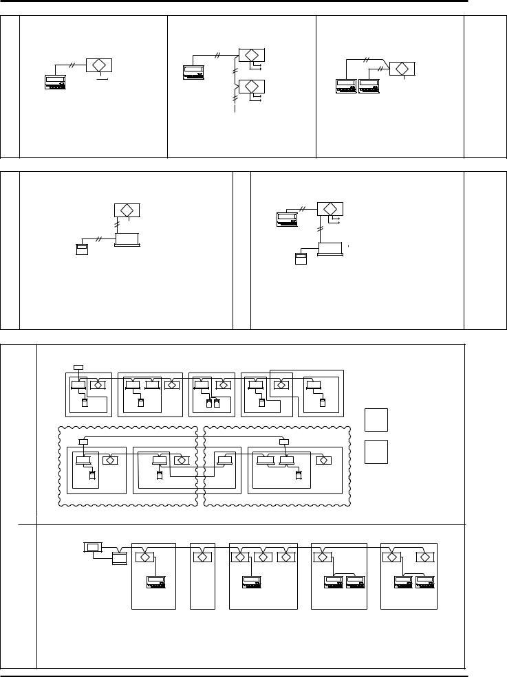
4.2System Examples
Basic System (Refer to page C-11)
One Lossnay with one remote controller
Non-polar |
Lossnay |
Two wires |
|

 Power supply
Remote controller
PZ-60DR-E or PZ-41SLB-E
●A simple system in which Lossnay is operated independently with one remote controller.
Multiple Lossnay units with one remote controller
Non-polar |
Lossnay |
|
Two wires |
(Main) |
|
|
||
|
Power supply |
|
|
Lossnay |
|
Remote |
(Sub) |
|
controller |
||
|
||
PZ-60DR-E or |
Power supply |
|
PZ-41SLB-E |
||
|
●Up to 15 Lossnay units can be controlled at one time with one remote controller.
Two remote controller system with one Lossnay
Non-polar |
|
Two wires |
Lossnay |
|

 Power supply
Remote controller
PZ-60DR-E or PZ-41SLB-E
●Lossnay can be controlled from two remote locations.
●The remote controller gives priority to the last operation function request.
with an Air Conditioning Unit |
(Refer to page C-13) |
Operation |
|
Operating with Mr. Slim
Lossnay

 Power supply
 Power supply
Mr. Slim Remote (indoor unit) controller
●The Lossnay remote controller (PZ-60DR-E, PZ-41SLB-E) cannot be used with this system.
●Use MA remote controller of Mr.Slim for switching Lossnay ON/OFF or the fan speed.
●The ventilation mode is “automatic ventilation”.
Operating with an External Device (Refer to page C-22)
Operating with an external device |
|
|
Non-polar |
Lossnay |
● Selection of inter- |
Two wires |
|
locked operation |
|
|
|
|
Power supply |
mode is possible. |
|
● Delayed start inter- |
|
Remote controller |
|
locked operation is |
PZ-60DR-E or |
|
possible. |
PZ-41SLB-E
 Power supply
Indoor unit
Remote controller
●Lossnay operation will be performed via the external device.
●Level signal or pulse signal input (12V DC, 24V DC, uncharged a-con- tact) is possible.
System |
City Multi and Lossnay Interlocked System |
M-NET |
Centralized Management System |
|
|
|
|
Air conditioning device and system control
Outdoor unit
Indoor |
Lossnay |
|
Indoor |
Indoor Lossnay |
Lossnay |
Indoor |
Lossnay |
Indoor |
|
|
|
unit |
Indoor |
|
|
||||
unit |
|
|
unit |
|
unit |
unit |
|
|
unit |
MA remote controller |
|
MA remote controller |
MA remote controller |
MA remote controller |
|
MA remote controller |
|||
Interlock-Group 1 |
Interlock-Group 2 |
Interlock-Group 3 |
Interlock-Group 4 |
|
Interlock-Group 5 |
||||
Refrigerant 1 |
|
|
|
Refrigerant 2 |
|
|
|
||
|
Outdoor unit |
|
|
|
|
|
Outdoor unit |
||
|
|
|
|
Lossnay |
|
|
|
|
|
Indoor |
Lossnay |
|
Indoor |
Indoor |
Indoor unit |
Indoor |
Lossnay |
||
unit |
|
|
|
unit |
|
||||
|
|
|
|
unit |
|
|
unit |
|
|
MA remote |
|
|
|
|
|
|
|||
|
|
MA remote controller |
|
MA remotecontroller |
|||||
controller |
|
|
|
|
|
|
|
|
|
Interlock-Group 1 |
|
Interlock-Group 2 |
|
Interlock-Group 3 |
|
||||
Group setting
Interlocked operation setting
● One Lossnay can be interlocked with 16 indoor units. In addition, PZ-60DR-E (non M-NET) can be connected for each Lossnay units.
Centralized controller
Power Lossnay |
Lossnay |
Lossnay Lossnay Lossnay |
Lossnay |
Lossnay |
Lossnay |
supply |
|
|
|
|
|
unit |
|
|
|
|
|
Lossnay |
|
Lossnay |
Lossnay |
|
Lossnay |
remote controller |
|
remote controller |
remote controller |
remote controller |
|
PZ-60DR-E |
|
PZ-60DR-E |
PZ-60DR-E |
PZ-60DR-E |
|
Group 1 |
Group 2 |
Group 3 |
Group 4 |
Group 5 |
|
●Detailed control such as start/stop, fan speed Extra-Low and ventilation mode control is possible from the Lossnay remote controller PZ-60DR-E.
●PZ-52SF-E (M-NET remote controller) can be used instead of PZ-60DR-E. However, function is limited and connecting position is different.
●Start/stop, fan speed and ventilation mode control is possible from the centralized controller.
●Controller can set up the group including maximum of 16 indoor or Lossnay units.
C-6

Two remote controller system with multiple Lossnay units

 Power supply
 Power supply
Remote controller
PZ-60DR-E or
PZ-41SLB-E
●It is also possible to operate two remote controller units when using multiple Lossnay units.
Interlocking multiple units
When the operation signal is an uncharged a-contact signal
Lossnay |
|
|
A/C |
A/C |
A/C |
Power supply |
Power supply |
Power supply |
Power supply |
|||
Remote controller |
Air conditioning |
|
Air conditioning |
Air conditioning |
||
PZ-60DR-E or |
unit side remote |
unit side remote |
unit side remote |
|||
PZ-41SLB-E |
controller |
|
controller |
|
controller |
|
●Interlocking is possible from multiple air conditioning units, etc. (excluding pulse input)
(Separately sold parts are necessary depending on the operation signal).
Interlocking/individual combined systems
Interlock settings are possible with the inclusion of a group setting. (Joint use of the air conditioner remote controller and Lossnay remote controller is possible.)
|
|
Operation settings |
|
Centralized |
|
Indoor unit of |
Lossnay (02) |
controller |
Outdoor |
air conditioner |
|
(000) |
(01) |
|
|
unit (51) |
|
||
|
|
|
|
|
|
MA remote |
Lossnay remote |
|
|
controller |
controller |
|
|
|
(PZ-60DR-E) |
|
|
Group 1 |
Group 2 |
( ) address
●Applicable indoor units are C type or later (for use with MA remote controller) models
●Set the different groups of indoor unit of air conditioner and Lossnay unit.
Use Lossnay remote controller PZ-60DR-E or PZ-41SLB-E .
(Do not use PZ-52SF-E).
Lossnay transmission connection terminal
Remote controller input terminal
2 

1 

TM4 PZ-60DR-E
Transmission wires
Setting
Change the setting on the main/sub switch (SW1) on the second and subsequent Lossnay units to “Sub”.
|
|
|
|
Main/Sub selection |
||||
|
|
|
-E) |
|
switch |
|||
Power |
|
|
|
(SW1) |
||||
|
|
Power |
Main Sub |
|||||
supply |
|
|
supply |
|
|
|
|
|
|
|
|
|
|
||||
|
|
|
|
|
|
|
|
|
|
device (Factory setting: main) |
|||||||
Power |
Lossnay |
|
|
|
|
|
||
supply |
|
|
|
Connect to |
||||
|
|
|
||||||
|
|
|
|
|||||
|
|
|
|
remote |
||||
|
|
|
Second |
controller |
||||
|
|
|
(PZ-60DR-E) |
|||||
|
|
|
||||||
|
|
|
Lossnay |
|
|
|
|
|
Power |
|
|
|
Connect |
||||
supply |
|
|
|
to third |
||||
MAX 15 units |
|
|
|
Lossnay |
||||
|
|
|
|
|
|
|
|
|
Transmission cable
Use Lossnay remote controller PZ-60DR-E .
(Do not use PZ-41SLB-E).
Lossnay transmission connection terminal
M-NET transmission cable input terminal block
TB5
A B S
|
|
|
|
|
|
|
|
Remote controller |
|
|
|
|
|
|
|
|
|
Shielded wire |
||||||||
|
|
|
|
|
|
|
|
input terminal |
M-NET
transmission cable
and PZ-52SF-E
2
1 

TM4 PZ-60DR-E
Transmission wires
Address Setting
SA1 SA2
10 digit |
1 digit |
Address setting switch
●When the address number has been changed, the data in the memory is automatically reset.
C-7

4.3System Selection
Interlocked with City Multi (Refer to page C-14)
Lossnay operation when indoor unit is stopped |
● |
|
Lossnay stopping when indoor unit is operating |
● |
|
|
|
|
Switching Lossnay fan speed |
|
|
|
When interlocked with indoor unit for compatibility with both R22, R407C and R410A |
High/Low |
|
When interlocked with indoor unit for other than the above |
Fixed to high |
Ventilation mode |
Fixed to automatic |
|
Filter maintenance indicator |
● |
|
Lossnay error indicator |
● |
|
Delayed operation |
● |
|
External control operating mode selection |
× |
|
Number of indoor units for interlocked group setting with one Lossnay unit |
16 units |
|
Number of Lossnay units for interlocked group setting with one indoor unit |
One unit |
|
* All Lossnay functions including Extra-Low fan speed can be controlled from PZ-60DR-E.
Interlocked with Mr. Slim (Refer to page C-13)
When using A-control remote controller
|
Lossnay operation when indoor unit is stopped |
● |
|
Lossnay stopping when indoor unit is operating |
× |
|
Lossnay fan speed switching |
High/Low |
Other common items |
|
|
|
Lossnay error indicator |
× |
|
Ventilation mode |
Fixed to automatic |
|
|
|
|
Filter maintenance indicator |
× |
|
Delayed operation |
● |
|
External control operating mode selection |
× |
|
Number of indoor units for interlocked group setting with one Lossnay unit |
One unit |
|
Number of Lossnay units for interlocked group setting with one indoor unit |
One unit |
Incase of PZ-60DR-E |
|
|
|
|
|||
|
|
Air |
|
|
Air |
Lossnay |
|
|
|
conditioner |
|
|
conditioner |
|
|
|
|
MA remote |
|
|
|
M-NET transmission cable |
|
|
|
|
|
||||
|
|
controller |
|
|
|
|
|
|
|
|
|
|
|
|
|
PZ-60DR-E can be used
Incase of PZ-52SF-E
Air conditioner
MA remote controller
Mr.Slim (A-control)
indoor unit
Remote controller
Air |
Lossnay |
|
conditioner |
||
|
M-NET transmission cable
PZ-52SF-E can be used
Lossnay unit |
Lossnay remote |
LGH-RX type |
controller |
|
PZ-60DR-E, |
|
PZ-41SLB-E |
|
cannot be used. |
Slim-Lossnay connecting cable (Enclosed accessory with Lossnay unit)
Independent Lossnay Unit (Not interlocked with City Multi or Mr. Slim systems.)
Start/Stop |
● |
|
Fan speed switching |
High/Low/Extra Low |
|
Ventilation mode |
Heat ex. / |
|
By-pass/ Auto |
||
|
||
Filter maintenance indicator |
● |
|
Lossnay error indicator |
● |
|
Delayed operation |
● |
|
External control operating mode selection |
● |
|
Number of Lossnay units |
15 units |
|
Number of remote controllers |
Two units |
* All Lossnay functions including Extra-Low fan speed can be controlled from PZ-60DR-E.
Lossnay unit
LGH-RX type
|
|
|
|
|
External signal source |
|
|
|
|
|
|
||
|
|
|
|
|
for interlocking |
|
Lossnay remote controller |
||||||
to the Lossnay |
||||||
(PZ-60DR-E, PZ41SLB-E) |
||||||
|
||||||
Interlocked with external device (BMS) (Refer to page C-22)
Start/Stop |
● |
Fan speed switching |
Fixed to high |
|
|
Ventilation mode switching |
Fixed to automatic |
Filter maintenance indicator |
× |
Lossnay error indicator |
× |
Delayed operation |
● |
External control operating mode selection |
● |
*● : Available
×: Not Available
External signal source for interlocking
to the Lossnay
Lossnay unit
LGH-RX type
C-8
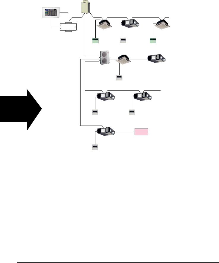
Centralized Controller System
Centralized controller
AG-150A
Outdoor unit
Interlocked with
City Multi indoor units
Indoor unit |
LOSSNAY RX5 |
Indoor unit |
Power supply unit |
|
|
(PAC-SC51KUA) |
|
M-NET remote |
M-NET remote |
LOSSNAY remote |
|
controller |
controller |
controller |
|
PZ-60DR-E |
|
Interlocked with
Mr. Slim indoor units
Mr.Slim |
Mr.Slim |
LOSSNAY RX5 |
indoor unit |
|
|
outdoor unit |
|
|
|
|
|
|
Mr.Slim |
|
|
remote controller |
|
LOSSNAY units only
LOSSNAY RX5 |
LOSSNAY RX5 |
LOSSNAY remote |
LOSSNAY remote |
controller |
controller |
PZ-60DR-E |
PZ-60DR-E |
Interlocked with external devices
LOSSNAY RX5 |
Ext. signal source |
LOSSNAY remote controller PZ-60DR-E
C-9

Reference: Remote controller for the Lossnay and indoor unit
Refer to the technical documentation related to the Remote controller for the indoor unit.
Remote controllers for Lossnay unit
Lossnay remote controller |
Lossnay remote controller |
Lossnay M-NET remote controller |
|
(PZ-60DR-E) |
(PZ-41SLB-E) |
(PZ-52SF-E) |
|
*non M-NET protocol |
*non M-NET protocol |
|
|
Advanced Lossnay remote controller. |
With Lossnay interlock switches |
Without Lossnay interlock switches |
|
|
and indicators. |
|
and indicators. |
|
2CONTROLLERS |
INTERLOCKED |
CENTRAL INTERLOCKED |
|
AUTO |
||
|
HEAT EX. |
||
|
BY-PASS HEAT EX. |
||
|
BY-PASS |
||
|
|
|
AUTO |
|
CHECK |
FILTER |
CHECK |
|
NOT AVAILABLE FILTER |
||
|
SETTING |
MIN. DELAYED |
|
|
|
|
ON/OFF |
|
DELAY START |
FILTER |
FILTER |
|
|
PZ-41SLB-E |
|
Remote controllers for City Multi indoor unit
MA remote controller (PAR-21MAA)
*non M-NET protocol With Lossnay interlock switches and indicators.
TIME SUN MON TUE WED THU FRI SAT
TIMER |
Hr |
ON |
AFTER |
AFTER |
OFF |
ERROR CODE |
|
FUNCTION |
|
|
FILTER |
|
|
WEEKLY |
|
|
SIMPLE |
ONLY1Hr. |
|
AUTO OFF |
|
TEMP. |
|
|
ON/OFF |
|
MENU |
ON/OFF |
|
FILTER |
BACK |
MONITOR/SET |
DAY |
|
CHECK TEST |
PAR-21MAA |
CLOCK |
OPERATION |
CLEAR |
|
ME remote controller (PAR-F27MEA)
Without Lossnay interlock switches and indicators.
|
CENTRALLY CONTROLLED |
1Hr. |
|
|
|
DAILY |
ON OFF |
|
|
|
AUTO OFF |
CLOCK |
|
|
|
|
REMAINDER |
|
FILTER |
|
|
|
|
CHECK MODE |
STAND BY |
|
|
|
TEST RUN |
|
ERROR CODE |
NOT AVAILABLE |
LIMIT TEMP. |
|
DEFROST |
|
|||
|
TEMP. |
|
ON/OFF |
|
|
|
CLOCK→ON→OFF |
|
FILTER |
|
|
|
|
|
|
|
|
|
CHECK TEST |
PAR-F27MEA |
TIMER SET |
|
|
|
Remote controllers for Mr. Slim indoor unit
PAR-21MAA
TIME SUN MON TUE WED THU FRI SAT
TIMER |
Hr |
ON |
AFTER |
AFTER |
OFF |
|
ERROR CODE |
|
ONLY1Hr. 


FUNCTION |
FILTER |
WEEKLY |
SIMPLE |
AUTO OFF |
|
TEMP. |
|
|
ON/OFF |
|
MENU |
ON/OFF |
|
FILTER |
BACK |
MONITOR/SET |
DAY |
|
CHECK TEST |
PAR-21MAA |
CLOCK |
OPERATION |
CLEAR |
|
C-10
4.4Basic System
4.4.1 System Summary
Design Example 1 Basic system
Non-polar |
Lossnay |
Two wires |
|

 Power supply
Remote controller
PZ-60DR-E or PZ-41SLB-E
●This is a simple system.
A Lossnay is operated independently with one remote controller.

 Design Example 2 Lossnay control of multiple units
Non-polar
Two wires
Remote controller PZ-60DR-E or PZ-41SLB-E
Lossnay  (Main)
 Power supply Lossnay
 (Sub)
(Sub) 
 Power supply
●Up to 15 Lossnay units can be controlled at one time with one remote controller switch.

 Design Example 3 Two remote controllers system
● The Lossnay can be controlled
Non-polar |
|
from two remote locations. |
|
|
● The remote controller gives pri- |
||
Two wires |
Lossnay |
||
ority to the last touch. |
|||
|
|||
|
|
||
|
Power supply |
|
|
Remote controller |
|
|
|
PZ-60DR-E or PZ-41SLB-E |
|
||
4.4.2 Operation of Multiple Units
Feature |
One remote controller can operate from one to 15 Lossnay units. PZ-60DR-E has many functions.such |
||
as Extra-Low fan speed, however, PZ-41SLB has limited function. |
|||
|
|||
|
|
||
Ordered part |
Remote controller |
||
PZ-60DR-E, PZ-41SLB-E |
|||
|
|||
|
|
|
|
|
• |
Also connect the power to the second and following Lossnay units. |
|
Notes |
• |
The maximum extension of the transmission cable is 500 m or less (between Lossnay and remote |
|
|
controller switch, between Lossnay and Lossnay). |
||
|
|
||
|
• |
The main or Sub setting on the Lossnay is necessary. |
|
|
|
|
|
When operating multiple Lossnay units
|
|
|
|
Main/Sub selection |
||||
|
|
|
-E) |
|
switch |
|||
Power |
|
|
|
(SW1) |
||||
|
|
Power |
Main Sub |
|||||
supply |
|
|
supply |
|
|
|
|
|
|
|
|
|
|
||||
|
|
|
|
|
|
|
|
|
|
device (Factory setting: main) |
|||||||
Power |
Lossnay |
|
|
|
|
|
||
supply |
|
|
|
Connect to |
||||
|
|
|
||||||
|
|
|
|
|||||
|
|
|
|
remote |
||||
|
|
|
Second |
controller |
||||
|
|
|
(PZ-60DR-E) |
|||||
|
|
|
||||||
|
|
|
Lossnay |
|
|
|
|
|
Power |
|
|
|
Connect |
||||
supply |
|
|
|
to third |
||||
MAX 15 units |
|
|
|
Lossnay |
||||
|
|
|
|
|
|
|
|
|
Transmission cable
(1)Connect from Lossnay Unit 1 to Lossnay Unit 2, and from Unit 2 to Unit 3 and so on up to a maximum of 15 units using a transmission cable (PVC insulated PVC jacketed and either between 0.65 and 1.2, or between 0.3 mm2 and 1.25 mm2 in cross section).
(2)Change the setting on the main/sub switch (SW1) on the second and subsequent Lossnay units to “Sub”.
CAUTION:
Don’t tighten screws of terminal block with a torque larger than 0.5 Nm. It could damage the PCB.
Note:
●Up to four 0.3 mm2 stranded wires or  0.65 PVC wires can be connected to one input terminal.
●For other types of wire, up to two can be connected.
●The operation signal and pulse signal can be connected to the external device of the main Lossnay only.
●Connect the power to each respective Lossnay unit.
●When the LGH-150RX5 and LGH-200RX5 types are connected, they operate at low fan speed even if extra low fan speed is selected.
C-11

4.4.3 Operation with two Remote controllers
|
Characteristics |
|
Remote controller |
Note |
||||||||
• |
Lossnay can be operated from two remote locations. |
|
|
|
|
|
|
|
|
• Use only up to two remote controllers |
||
• |
Lossnay conditions can be checked from two remote |
|
Lossnay remote controller |
(Operation will not go normally if three |
||||||||
|
locations. |
|
|
PZ-60DR-E, PZ-41SLB-E |
remote controller switches are con- |
|||||||
• |
The remote controller gives priority to the last touch. |
|
|
|
|
|
|
|
|
nected.) |
||
|
|
|
|
|
|
|
|
|
|
|
|
|
System Example |
|
|
|
|
|
|
|
|
|
|
||
|
Transmission |
|
|
|
|
|
|
|
|
|
|
|
|
cable extension |
Lossnay |
Lossnay |
|
||||||||
|
is 500 m or less |
|
||||||||||
|
0.65 to 1.2 |
|
|
|
|
|
|
|
|
|
|
MAX 15 units. |
|
PVC cable or |
|
|
|
|
|
|
|
|
|
||
|
|
|
|
|
|
|
|
|
|
|
||
|
0.3 mm2 to 1.25 mm2 |
|
|
|
|
Power supply |
|
|
Power supply |
|
||
|
|
|
|
|
|
|
|
|||||
|
|
|
|
|
|
|
|
|||||
|
strand wire. |
|
|
|
|
|
|
|
||||
|
|
|
|
|
|
|
|
|||||
|
|
|
|
|
|
|
|
|
|
|
||
Remote controller
PZ-60DR-E or PZ-41SLB-E
|
Lossnay |
Lossnay |
|
|
|
|
|
|
|
MAX 15 units. |
|
|
Power supply |
Power supply |
|
|
|
|
Remote controller |
|
|
||
Transmission |
PZ-60DR-E or PZ-41SLB-E |
|
|
||
cable extension |
|
|
|
|
|
is 500 m or less |
|
|
Lossnay |
Lossnay |
|
0.65 to 1.2 |
|
|
|||
PVC cable or |
|
|
|
|
|
0.3 mm2 to 1.25 mm2 |
|
|
|
|
|
strand wire. |
|
|
Power supply |
Power supply |
|
|
|
|
|||
|
Remote controller |
Remote controller |
|
|
|
|
PZ-60DR-E or |
PZ-60DR-E or |
|
|
|
|
PZ-41SLB-E |
PZ-41SLB-E |
|
|
|
Operation Method
The operation is the same with each remote controller. In this case, the Lossnay gives operating priority to the last button push.
C-12

4.5Interlocking with Mr. Slim
4.5.1 Interlocked Mr. Slim and Lossnay System
Features
● It is possible to Interlock Mr. Slim indoor units with Lossnay operation.
System Example
Mr. Slim outdoor unit
|
|
|
|
|
|
|
|
|
|
|
|
|
|
|
|
|
|
|
|
|
|
|
|
|
|
|
|
|
|
|
|
|
|
Mr.Slim indoor unit |
|
|
|
|
Lossnay unit |
||||||||
|
|
|
|
|
|
||||||||||
|
|
|
|
||||||||||||
|
|
|
|
|
|
|
|
|
|
|
|
|
|
||
|
|
|
|
|
|
|
|
|
|
|
|
|
|
||
|
|
|
|
|
|
|
|
|
|
|
|
|
|
||
|
|
|
|
|
|
|
|
|
|
|
|
|
|
||
|
|
|
|
|
|
|
|
|
|
|
|
Slim-Lossnay LGH-RX type |
|||
|
|
|
|
|
|
|
|
|
|
|
|
connection cable |
|||
|
|
|
|
|
|
|
|
|
|
|
|
(Enclosed accessory with Lossnay unit) |
|||
Remote controller |
|||||||||||||||
|
|
|
|||||||||||||
Lossnay Function Table (Interlocked settings)
Item |
Details |
|
|
Number of indoor units that can be set to interlocked opera- |
One unit |
tion with one Lossnay unit in each group |
|
|
|
Number of Lossnay units that can be set to interlocked oper- |
One unit |
ation with one indoor unit |
|
|
|
Operation of Lossnay unit only |
Possible |
(When indoor unit is stopped) |
|
|
|
Independent Lossnay unit start and stop |
Not possible |
(When indoor unit is operating) |
|
|
|
Delayed operation |
30 minutes delayed operation of Lossnay when indoor unit |
(Optional setting) |
cooling/heating operation is started (Lossnay Dip-SW setting). |
|
|
Switching fan speed |
High/Low |
|
|
Ventilation mode |
Fixed to automatic |
|
|
Filter indicator |
Not possible |
|
|
Error |
Not possible |
|
|
Restrictions and precautions |
* The Lossnay remote controller (PZ-60DR-E, PZ-41SLB-E) |
|
cannot be used on systems interlocked with Mr. Slim. |
|
|
C-13

4.6Combining with City Multi
4.6.1Independent Lossnay System with Lossnay M-NET Remote Controller and MELANS
Features
●The Mitsubishi Electric air-conditioner network system (MELANS) can operate and monitor each group of Lossnay units and City Multi indoor units.
●Can also use the Lossnay M-NET remote controller to operate.
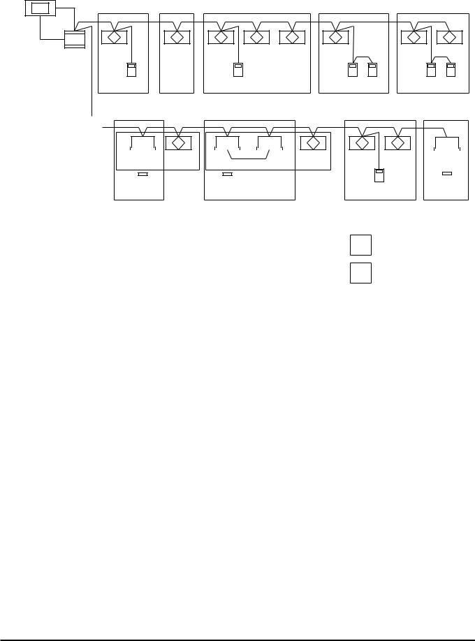
System Examples: 1 (Lossnay Non M-NET Remote Controller PZ-60DR-E)
The following groups can be configured.
Centralized controller (000) |
|
|
|
|
|
|
( |
) address |
|
|
|
|
|
|
|
||
M-NET |
|
|
|
|
|
|
|
|
Power |
Lossnay |
Lossnay |
Lossnay |
Lossnay |
Lossnay |
Lossnay |
Lossnay |
Lossnay |
(001) |
(002) |
(003) |
(004) |
(005) |
(006) |
(007) |
(008) |
|
supply |
|
|
|
|
|
|
|
|
unit |
|
|
|
|
|
|
|
|
|
Lossnay remote |
|
Lossnay remote |
|
Lossnay remote |
Lossnay remote |
||
|
controller PZ-60DR-E |
|
controller PZ-60DR-E |
|
controller PZ-60DR-E |
controller PZ-60DR-E |
||
|
Group1 |
Group2 |
Group3 |
|
|
Group4 |
Group5 |
|
 M-NET
M-NET
Outdoor unit (059)
Indoor |
Lossnay |
Indoor |
|
unit |
(010) |
unit |
|
(009) |
|
(011) |
|
MA Remote |
Lossnay remote |
MA Remote |
|
controller |
controller |
||
controller PZ-60DR-E |
|||
|
|
||
Group6 |
|
Group7 |
Indoor |
Lossnay |
Lossnay |
Lossnay |
Indoor |
unit |
(013) |
(014) |
(015) |
unit |
(012) |
|
|
|
(016) |
|
Lossnay remote |
Lossnay remote |
MA Remote |
|
|
controller |
|||
|
controller PZ-60DR-E |
controller PZ-60DR-E |
||
|
|
|||
|
|
Group8 |
|
Group9 |
Group 1 : One Lossnay unit and one Lossnay remote controller. Group 2 : Without a Lossnay remote controller.
Group 3 : Multiple Lossnay units and one Lossnay remote controller. Group 4 : One Lossnay unit and two Lossnay remote controllers. Group 5 : Multiple Lossnay units and two Lossnay remote controllers.
Group 6 : One Lossnay unit is interlocked to one indoor unit(PZ-60DR-E is not necesally).
Group 7 : One Lossnay unit is interlocked to multiple indoor units(PZ-60DR-E is not neccesally).
Group 8 : Multiple Lossnay units connected to indoor unit transmission cable side and one Lossnay remote controller.
Group 9 : Without Lossnay units.
Group setting
Interlocked operation setting
Caution:
●Hard wire connection from PZ-60DR-E is required independent from M-NET line. If change the Group setting in the future, it is required to change the wiring of PZ-60DR-E.
●In this application, Lossnay remote controller PZ-41SLB-E cannot be used.
C-14
System Examples: 2 (Lossnay M-NET Remote Controller PZ-52SF-E)
The following groups can be configured.
● Further information please refer LGH-RX4 Technical Manual.
Centralized controller (000) |
( ) address |
|
Power |
|
|
|
|
|
|
Lossnay |
Lossnay |
Lossnay |
Lossnay |
Lossnay |
Lossnay |
|
Lossnay |
Lossnay |
|||||
(001) |
(002) |
(003) |
(004) |
(005) |
(006) |
|
(007) |
(008) |
||||||||||||
supply |
|
|
|
|
|
|
|
|
|
|
|
|
|
|
|
|||||
unit |
(101) |
|
|
(103) |
|
(106) |
(156) |
(107) |
(157) |
|||||||||||
|
|
|
|
|
|
|
|
|
|
|
Lossnay M-NET remote |
|
Lossnay M-NET remote |
|
Lossnay M-NET remote |
Lossnay M-NET remote |
||||
|
|
|
|
|
|
|
|
|
|
|
|
controller PZ-52SF-E |
|
controller PZ-52SF-E |
|
controller PZ-52SF-E |
controller PZ-52SF-E |
|||
|
|
|
|
|
|
|
|
|
Group1 |
Group2 |
Group3 |
|
|
Group4 |
|
Group5 |
|
|||
|
|
|
|
|
|
|
|
|
|
|
|
|
|
|
|
|
|
|
|
|
|
|
|
|
|
|
|
|
|
|
|
|
|
|
|
|
|
|
|
|
|
|
|
|
|
|
|
|
|
|
|
|
|
|
|
|
|
|
|
|
|
|
Outdoor unit |
|
|
|
|
|
|
|
|
|
|
|
|
|
|
|
|
|
|
|
|
|
|
|
|
(059) |
|
|
|
|
|
|
|
|
|
|
|
|
|
|
|
|
|
|
|
|
|
|
|
|
|
|
|
|
|
|
|
|
|
|
|
|
|
|
|
|
|
|
|
|
|
|
|
|
|
|
Indoor |
|
|
|
Lossnay |
Indoor |
|
|
|
Indoor |
Lossnay |
Lossnay |
Lossnay |
Indoor |
|
|
|
|||||||
|
unit |
|
|
|
(010) |
unit |
|
|
|
unit |
(013) |
(014) |
(015) |
unit |
|
|
|
|||||||
|
(009) |
|
|
|
|
|
(011) |
|
|
|
|
(012) |
|
|
|
(016) |
|
|
|
|
||||
|
|
|
|
|
|
|
|
|
|
|
|
|
|
|
|
|
|
|
|
|
|
|
||
|
MA Remote |
|
MA Remote |
|
|
|
Lossnay M-NET remote |
MA Remote |
||||||||||||||||
|
controller |
|
controller |
|
|
|
controller PZ-52SF-E (114) |
controller |
||||||||||||||||
|
Group6 |
|
Group7 |
|
|
|
Group8 |
|
Group9 |
|||||||||||||||
Group 1 : One Lossnay unit and one Lossnay M-NET remote controller. Group 2 : Without a Lossnay M-NET remote controller.
Group 3 : Multiple Lossnay units and one Lossnay M-NET remote controller. Group 4 : One Lossnay unit and two Lossnay M-NET remote controllers. Group 5 : Multiple Lossnay units and two Lossnay M-NET remote controllers. Group 6 : One Lossnay unit is interlocked to one indoor unit.(PZ-60DR-E is not
necesally)
Group 7 : One Lossnay unit is interlocked to multiple indoor units.(PZ-60DR-E is not neccesally)
Group 8 : Multiple Lossnay units connected to indoor unit transmission cable side and one Lossnay M-NET remote controller.
Group 9 : Without Lossnay units.
Group setting
Interlocked operation setting
Caution:
●If change the Group setting in the future, no need to change the M-NET wiring, Just change the address setting from centralized controller.
●In this application, Lossnay remote controller PZ-41SLB-E cannot be used.
C-15

Lossnay Function Table (Group Setting)
Item |
Details |
|
|
|
|
Number of Lossnay remote controllers and/or MELANS |
Five units |
|
(Number of Lossnay remote controller(PZ-60DR-E or PZ- |
||
remote controllers that can be connected to one Lossnay unit |
||
52SF-E) is two units max.) |
||
|
||
|
|
|
Operation of two remote controllers in one group |
Possible |
|
|
|
|
Switching fan speed |
High/Low (Extra-Low from PZ-60DR-E) |
|
|
|
|
Ventilation mode |
Heat exchange / By-pass / Automatic |
|
|
|
|
Filter maintenance indicator |
3000 hours / No display |
|
|
|
|
Error |
Display |
|
|
|
Controller Function Table
|
|
|
Local Remote |
|
|
MELANS Series |
|
||||
|
|
|
|
|
|
|
|
|
|
|
|
|
|
Lossnay |
Lossnay |
Remote |
|
Simple |
Group |
System |
Schedule |
ON/OFF |
Centralized |
|
Model |
remote |
remote |
|
remote |
remote |
remote |
remote |
|||
|
controller |
controller |
controller |
controller |
controller |
controller |
timer |
controller |
controller |
||
|
|
|
|
|
|
|
|
|
|
|
|
|
|
PZ-52SF-E |
PZ-60DR-E |
PAR-21MAA |
PAC-SE51CRA |
PAC-SC30GRA |
PAC-SF44SRA |
PAC-YT34STA |
PAC-YT40ANRA |
AG-150A |
|
|
|
(M-NET) |
|
PAR-F27MEA |
PAC-YT51CRA |
|
|
|
|
|
|
|
|
|
|
|
|
|
|
|
|
|
|
No. of controllable (Groups/Units) |
1 Group/16 Units |
1 Group/15 Units |
|
|
|
|
50 Group/50 Units |
50 Group/50 Units |
16 Group/50 Units |
50 Group/50 Units |
|
|
|
|
|
|
|
|
|
|
|
|
|
|
Start/Stop |
« |
« |
|
|
|
|
n |
n |
n |
n |
Operation |
Switching air volume |
« |
« |
|
|
|
|
n |
× |
× |
n |
|
|
|
|
|
|||||||
|
Switching Ventilation mode |
« |
« |
|
|
|
|
n |
× |
× |
n |
|
Priority instructions to local remote |
× |
× |
|
|
|
|
n |
*1 |
× |
n |
|
controller (Local permitted) |
|
|
|
|
||||||
|
|
|
|
|
|
||||||
|
|
|
|
|
|
|
|
|
|
|
|
|
|
|
|
|
|
|
|
|
|
|
|
|
Status (Operation/Stop) |
« |
« |
|
|
|
|
n |
n |
n |
n |
|
Switching air volume |
« |
« |
|
|
|
|
« |
× |
× |
« |
Monitoring |
Error information |
« |
« |
|
|
|
|
n |
n |
× |
n |
|
Ventilation mode |
« |
« |
Not applicable with non-interlocked |
« |
× |
× |
« |
|||
|
Error |
« |
« |
Lossnay units |
|
n |
n |
« |
n |
||
|
|
|
|
|
|
|
|
|
|
|
|
|
Filter maintenance indicator |
« |
« |
|
|
|
|
« |
× |
× |
« |
|
Local permitted |
« |
« |
|
|
|
|
« |
× |
× |
« |
|
Weekly |
× |
« |
|
|
|
|
× |
« |
× |
« |
Scheduling/ Recording |
Minimum setting (minutes) |
× |
1 |
|
|
|
|
× |
5 |
× |
1 |
|
Stop/Starts per day |
× |
16 |
|
|
|
|
× |
16 |
× |
24 |
|
Stop/Starts per week |
× |
112 |
|
|
|
|
× |
112 |
× |
24x7*2 |
|
|
|
|
|
|
|
|
|
|
|
|
|
Error record |
× |
« |
|
|
|
|
« |
× |
× |
« |
Switches and display |
|
n: Group/batch |
|
|
« : Group only (or function available) |
||||||
|
|
|
: Available under some condition |
× : Not available |
|
|
|||||
|
|
|
*1 Available as a scheduled operation |
|
|
|
|
||||
|
|
|
*2 You can set a schedule for the year and a weekly schedule for individual seasons. |
||||||||
●For details about the operation and display of the Lossnay remote controller (PZ-60DR-E), Refer to page C-78.
●For details about the operation and display of the Lossnay M-NET remote controller (PZ-52SF-E), Refer to page C-92.
●For details about the operation and display of the centralized controller (AG-150A), Refer to page C-93.
C-16

4.6.2 City Multi and Lossnay Interlocked System
Characteristics
●It is possible to interlock City Multi indoor units with Lossnay operation.
●Independent Lossnay operation can also be performed using MA remote controller or ME remote controller.
●Non M-NET Lossnay remote controller PZ-60DR-E can be used with any Lossnay units in this application.
System Examples
The following groups can be configured.
Single Refrigerant System
Outdoor unit (051)
Non M-NET Lossnay remote controller PZ-41SLB-E cannot be used with any group in this application.
( ) address
|
|
|
|
|
|
|
|
|
|
|
|
|
|
|
|
|
|
|
|
|
|
|
|
|
|
|
|
|
|
|
|
|
|
|
Indoor |
|
|
Lossnay |
Indoor |
|
|
|
|
Indoor Lossnay |
Indoor |
|
|
Lossnay |
Indoor |
|
|
|
Lossnay |
Indoor |
|
|
|
||||||||||||
unit |
|
|
(002) |
unit |
|
|
|
|
unit |
(005) |
unit |
|
(007) |
unit |
|
|
|
(009) |
unit |
|
|
|
||||||||||||
(001) |
|
|
|
(003) |
|
|
|
|
(004) |
|
(006) |
|
|
|
|
(008) |
|
|
|
|
(010) |
|
|
|
||||||||||
MA |
|
|
|
|
|
|
|
|
|
|
|
|
|
|
|
|
|
|
|
|
|
|
|
|
|
|
|
|
|
|
|
|
||
|
|
|
|
|
|
|
|
|
|
|
|
|
|
|
|
|
|
|
|
|
|
|
|
|
|
|
|
|
|
|
|
|
||
Remote |
MA Remote |
|
|
|
MA Remote |
MA Remote |
|
MA Remote |
||||||||||||||||||||||||||
controller |
|
controller |
|
|
|
controller |
controller |
|
controller |
|||||||||||||||||||||||||
Group1 |
|
Group2 |
|
|
Group3 |
|
|
|
Group4 |
|
|
|
Group5 |
|||||||||||||||||||||
Group 1 : One Lossnay unit is interlocked to one indoor unit. Group 2 : One Lossnay unit is interlocked to multiple indoor units.
Group 3 : One indoor unit with two remote controllers is interlocked to one Lossnay unit. Group 4, 5 : Multiple groups are interlocked to one Lossnay unit.
Group setting
Interlocked operation setting
Multiple Refrigerant Systems
|
( ) address |
Refrigerant 1 |
Refrigerant 2 |
Outdoor unit (051) |
Outdoor unit (055) |
Indoor |
Lossnay |
Indoor |
Lossnay |
Indoor |
Indoor |
Indoor |
Lossnay |
unit |
(002) |
unit |
(004) |
unit |
unit |
unit |
(008) |
(001) |
|
(003) |
|
(005) |
(006) |
(007) |
Group setting |
MA Remote |
|
MA Remote |
|
|
MA Remote |
|
Interlocked |
controller |
|
controller |
|
|
controller |
|
|
Group1 |
|
Group2 |
|
|
Group3 |
|
operation setting |
|
|
|
|
|
Group 1 : One Lossnay unit is interlocked to one indoor unit.
Group 2 : One Lossnay unit is interlocked to multiple indoor units (with different refrigerants). Group 3 : One Lossnay unit is interlocked to multiple indoor units (with same refrigerant).
C-17

Lossnay Function Table (Interlocked Settings)
|
Item |
Details |
|
|
|
Number of indoor units that can be set to interlocked opera- |
16 units per group |
|
tion with one Lossnay unit in each group |
|
|
|
|
|
Number of Lossnay units that can be set to interlocked oper- |
one unit |
|
ation with one indoor unit |
|
|
|
|
|
Independent Lossnay start/stop operation |
Possible |
|
|
|
|
Delayed operation |
30-minutes delayed operation when indoor unit cooling/heat- |
|
(Optional setting by Lossnay PCB) |
ing operation is started |
|
|
|
|
Fan speed switching |
Indoor unit compatible with both R22, |
High/Low |
|
R407C and R410A |
|
|
|
|
|
Units other than the above |
Fixed to high |
|
|
|
Ventilation mode |
Fixed to automatic |
|
|
|
|
Filter maintenance indicator |
3000 hours / No display |
|
|
|
|
Error |
Display |
|
|
|
|
Restrictions and precautions |
* Lossnays cannot be interlocked to the indoor units using |
|
|
|
K-transmission converter. |
|
|
|
Note:
● In case of PZ-60DR-E is installed, additional function is available.
Lossnay Controller Function Table
|
|
Local Remote |
|
|
MELANS Series |
|
||
|
Lossnay |
Lossnay Remote |
Simple |
Group |
System |
Schedule |
ON/OFF |
Centralized |
Model |
remote |
remote |
remote |
remote |
remote |
remote |
||
controller controller controller controller controller controller |
timer |
controller controller |
||||||
|
|
PZ-52SF-E |
PZ-60DR-E |
PAR-21MAA PAC-SE51CRA |
PAC-SC30GRA PAC-SF44SRA PAC-YT34STA PAC-YT40ANRA |
AG-150A |
|||||
|
|
|
|
PAR-F27MEA PAC-YT51CRA |
|
|
|
|
|
||
No. of controllable (Groups (G)/Units) |
1 Group/16 Units |
1 Group/15 Units |
1 Group/16 Units |
1 Group/16 Units |
8 Group/16 Units |
50 Group/50 Units 50 Group/50 Units |
16 Group/50 Units 50 Group/50 Units |
||||
Operation |
Start/Stop |
« |
« |
« |
« |
n |
n |
n |
n |
n |
|
Switching air volume |
« |
« |
« |
× |
« |
« |
× |
× |
« |
||
|
|||||||||||
|
Switching ventilation mode |
« |
« |
× |
× |
× |
× |
× |
× |
× |
|
|
Prohibit Local |
× |
× |
× |
× |
× |
n |
*2 |
× |
n |
|
|
|
||||||||||
|
Status (Operation/Stop) |
« |
« |
« |
× |
« |
*1 |
n |
n |
n |
|
|
|
||||||||||
Monitoring |
Switching air volume |
« |
« |
« |
× |
« |
× |
× |
× |
« |
|
Error information |
« |
« |
« |
« |
n |
n |
n |
× |
n |
||
|
Ventilation mode |
« |
« |
× |
× |
× |
× |
× |
× |
× |
|
|
Error |
« |
« |
« |
« |
n |
n |
n |
n |
n |
|
|
Filter maintenance indicator |
« |
« |
« |
× |
« |
« |
× |
× |
« |
|
|
Permit/Prohibit for remote control |
× |
« |
« |
« |
« |
« |
× |
× |
« |
|
Scheduling/ Recording |
Weekly |
× |
« |
× |
× |
× |
× |
« |
× |
« |
|
Stop/Starts per day |
× |
16 |
2 |
× |
× |
× |
16 |
× |
24 |
||
|
|||||||||||
|
Stop/Starts per week |
× |
112 |
× |
× |
× |
× |
112 |
× |
24x7*3 |
|
|
Minimum setting (minutes) |
× |
1 |
10 |
× |
× |
× |
5 |
× |
1 |
|
|
Error record |
× |
« |
× |
× |
× |
« |
× |
× |
« |
|
Switches and display |
n: Group/batch |
« : Group only (or function available) |
|
|
: Available under some condition |
× : Not available |
|
|
*1 |
Does not display which interlocked Lossnay unit is operating in which group |
|
|
*2 |
Available as schedule operation |
|
|
*3 |
You can set a schedule for the year and a weekly schedule for individual seasons. |
|
●For details about the operation or display of the remote controller (PAR-F27MEA, PAR-21MAA), please refer to the specific remote controller manuals.
C-18

4.6.3MA Remote Controller/ME Remote Controller in Combination with Lossnay Non-M-NET Remote Controller (PZ-60DR-E)
System
Combining MA, ME and Lossnay Non M-NET remote controllers is permitted.
● In case of combination with Lossnay M-NET remote controller (PZ-52SF-E) please refer LGH-RX4 Technical Manual.
Combining Indoor Unit of Air Conditioner Remote Control and Lossnay Remote Control
Indoor Unit |
Lossnay LGH-RX5 type |
|
|
Model for MA remote control (Type C or later) |
« |
|
|
Model for other than MA remote control (Type B or earlier) |
× |
|
|
« : Compatible × : Incompatible |
|
System Examples: 1
Centralized controller (000)
Interlocked operation setting
Power |
|
Indoor unit of |
Lossnay |
|
Outdoor unit |
air conditioner |
(002) |
|
|
supply |
(001) |
|
|
|
(051) |
|
|
||
unit |
|
|
|
|
|
|
|
|
|
|
|
MA remote |
Lossnay remote |
|
|
|
controller |
controller |
|
|
|
(101) |
PZ-60DR-E |
( ) address |
Setting Method
(1)Make the Group setting for the indoor unit.
(2)Make the Group setting for the Lossnay unit.
(3)Set the indoor unit and Lossnay unit for interlocked operation.
When using the centralized controller, make both the Group setting and operation setting with centralized controller.
Characteristics
(1)When the indoor unit is set for interlocked operation in one group:
Interlocked Lossnay operation is possible with indoor unit remote controller. In this case, operation can switch between High/Low/Off. It is possible to switch Lossnay operation only between High/Low/Off with the indoor unit remote controller.
It is possible to controll the Lossnay unit from Lossnay remote controller PZ-60DR-E. More additional function such as Extra Low fan speed is available.
(2)When two or more indoor units in different groups are set for interlocked operation, the Lossnay will operate if at least one group operates. The Lossnay will stop operation if all groups stop operation.
It is possible to switch the Lossnay only between High/Low when other groups are operating with indoor unit remote controller.
It is possible to controll the Lossnay unit from Lossnay remote controller PZ-60DR-E. More additional function such as Extra Low fan speed is available.
Note:
●If the display on the MA, ME or other indoor unit remote controllers is cancelled, the indoor unit remote controller will not show the ventilation display even if Lossnay is operating via the Lossnay remote controller PZ-60DR-E.
Note:
Power supply limitation of transmission cable for indoor unit.
●Indoor units + ME remote controllers (compact remote controllers) is less than or equal to 40 units.
●Indoor units are less than or equal to 20 units.
(MA remote controllers and Lossnay units are not included in the 20 units, listed above.)
C-19

System Examples: 2
A sophisticated system including City Multi can also be configured.
Centralized controller (000)
( ) address
M-MET
|
Power |
Lossnay |
Lossnay |
Lossnay |
Lossnay |
Lossnay |
Lossnay |
|
Lossnay Lossnay(008) |
||
|
(001) |
(002) |
(003) |
(004) |
(005) |
|
(006) |
|
(007) |
||
|
supply |
|
|
|
|
|
|
|
|
|
|
|
unit |
|
|
|
|
|
|
|
|
|
|
|
|
Lossnay remote |
|
Lossnay remote |
|
|
|
Lossnay remote |
Lossnay remote |
||
|
Outdoor unit |
controller PZ-60DR-E |
|
controller PZ-60DR-E |
|
|
|
controller PZ-60DR-E |
controller PZ-60DR-E |
||
|
Group1 |
Group2 |
Group3 |
|
|
|
Group4 |
|
Group5 |
||
|
(059) |
|
|
|
|
||||||
|
M-MET |
|
|
|
|
|
|
|
|
|
|
|
Indoor unit |
Lossnay |
Indoor unit |
Indoor unit |
Lossnay |
|
Lossnay |
Lossnay |
Indoor unit |
||
|
(009) |
(010) |
(011) |
(012) |
(013) |
|
|
(014) |
(015) |
|
(016) |
|
|
(109) |
|
(111) |
|
|
|
|
|
|
(116) |
|
ME |
Lossnay remote |
ME |
|
Lossnay remote |
|
Lossnay remote |
|
ME |
||
|
remote controller |
controller PZ-60DR-E |
remote controller |
controller PZ-60DR-E |
|
controller PZ-60DR-E |
|
remote controller |
|||
|
Group6 |
|
Group7 |
|
|
|
Group8 |
|
Group9 |
||
|
|
|
|
|
|
|
|
|
|
|
Group setting |
|
|
|
|
|
|
|
|
|
|
|
Interlocked |
|
|
|
|
|
|
|
|
|
|
|
operation setting |
Group 1 |
: One Lossnay unit and one Lossnay remote controller. |
|
|
|
|
|
|
||||
Group 2 |
: Without Lossnay remote controller. |
|
|
|
|
|
|
|
|||
Group 3 |
: Multiple Lossnay units and one Lossnay remote controller. |
|
|
|
|
|
|||||
Group 4 |
: One Lossnay unit and two Lossnay remote controllers. |
|
|
|
|
|
|
||||
Group 5 |
: Multiple Lossnay units and two Lossnay remote controllers. |
|
|
|
|
|
|||||
Group 6 |
: One Lossnay unit is interlocked to one indoor unit. (PZ-60DR-E is not necessary) |
|
|
||||||||
Group 7 |
: One Lossnay unit is interlocked to multiple indoor units. (PZ-60DR-E is not necessary) |
||||||||||
Group 8 |
: Multiple Lossnay units connected to an indoor unit transmission cable |
|
|
||||||||
|
and one Lossnay remote controller. |
|
|
|
|
|
|
|
|||
Group 9 |
: Without Lossnay units. |
|
|
|
|
|
|
|
|
|
|
Note:
●Hard wire connection from PZ-60DR-E is required independent from M-NET line. If change the Group setting in the future, it is required to change the wiring of PZ-60DR-E.
●Do not use Lossnay remote controller PZ-41SLB-E.
C-20
4.6.4 When Using the LONWORKS® Compatible Adaptor (LMAP02-E) to Connect to LONWORKS®
By using the LON® adaptor (model name: LMAP02-E) to connect to LONWORKS®, it is possible to control and observe Lossnay operation on a building management system.
* For specifications and functions of the LON® adaptor, refer to the materials regarding the LONWORKS® compatible adaptor.
Table of Functions
|
|
Individual Lossnay |
Interlocked Lossnay |
|
|
Contents |
(Lossnay not set |
(Lossnay set for |
|
|
for interlocked |
interlocked opera- |
||
|
|
|||
|
|
operation) |
tion with City Multi) |
|
|
|
|
|
|
|
ON/OFF |
« |
× |
|
Operation |
Switch fan to High/Low |
« |
× |
|
Switch ventilation mode |
« |
× |
||
|
||||
|
Prohibit local ON/OFF operation |
« |
× |
|
|
Operation condition |
« |
× |
|
|
Fan speed |
« |
× |
|
Monitoring |
Ventilation mode (conditions) |
« |
× |
|
Errors |
« |
« |
||
|
||||
|
Filter maintenance indicator |
« |
× |
|
|
Prohibit local ON/OFF operation |
« |
× |
« : Available ×: Not Available
System Example
(Using M-NET)
|
|
M-NET |
|
Building |
LMAP02-E |
|
|
management |
|
Lossnay |
Lossnay |
system |
|
||
|
|
|
|
LONWORKS |
|
Lossnay |
Lossnay |
|
|
remote controller |
remote controller |
|
|
PZ-60DR-E |
PZ-60DR-E |
|
LMAP02-E |
|
|
|
M-NET |
Lossnay |
Lossnay |
|
|
Lossnay |
Lossnay |
|
|
remote controller |
remote controller |
|
|
PZ-60DR-E |
PZ-60DR-E |
Connect the M-NET transmission cable to TB5 A,B of the Lossnay terminal block. (Refer to page C-71). The Lossnay remote controller (PZ-41SLB-E) cannot be used with this system.
Up to 50 units can be connected with one LMAP02-E.
For details about the system or connection cables of the LMAP02-E, refer to its technical materials.
*LONWORKS® is a registered international trademark, registered in the U.S.A. to the Echelon Corporation.
C-21

5.Examples of Applications Using Various Input and Output Terminals
Various applications are possible by using the input/output terminals and connectors as shown below.
Input/Output Specifications
|
Terminal |
|
Specification |
Page |
|
|
|
|
|
||
1 |
External control input |
TM2 is the input terminal block for start/stop the Lossnay unit using external |
C-26/C-27 |
||
|
terminal block for |
equipment, such as a Mr. Slim (A-control) indoor unit or the BMS (Building |
C-28/C-73 |
||
|
start/stop the Lossnay |
Management System). |
|
|
|
|
unit |
Use voltage (12V-24V DC) or uncharged a-contact for signal input. |
|
||
|
|
(Both voltage and no-voltage signals are compatible with pulse input; a pulse |
|
||
|
(TM2 1 2 3) |
signal duration of 200 ms or more is needed. Set DIP switch 2-2 to ON.) |
|
||
|
|
|
|
||
2 |
Lossnay operation moni- |
Output terminal during Lossnay unit operation. (uncharged a-contact signal output.) |
C-26/C-27 |
||
|
tor output terminal block |
Output delay function 1 is possible by DIP switch 2-8 |
C-70/C-74 |
||
|
or |
Contactor rating: |
Max 240V AC, |
2A |
|
|
Output delay function 1 |
|
24V DC, |
2A |
|
|
|
|
Min 220V AC, |
100mA |
|
|
(TM4 9 0) |
|
5V DC, |
100mA |
|
|
|
|
|
||
3 |
Lossnay malfunction |
Output terminal during Lossnay unit malfunction. (uncharged a-contact signal output.) |
C-26/C-27 |
||
|
monitor output terminal |
Contactor rating: |
Max 240V AC, |
1A |
|
|
block |
|
24V DC, |
1A |
|
|
|
|
Min 220V AC, |
100mA |
|
|
(TM3 7 8) |
|
5V DC, |
100mA |
|
|
|
|
|
||
4 |
By-pass monitor output |
Output terminal during Lossnay unit malfunction. (uncharged a-contact signal output.) |
C-26/C-27 |
||
|
terminal block |
Output delay function 2 is possible by DIP switch 5-6 |
C-75 |
||
|
or |
Contactor rating: |
Max 240V AC, |
1A |
|
|
Output delay function 2 |
|
24V DC, |
1A |
|
|
|
|
Min 220V AC, |
100mA |
|
|
(TM3 6 7) |
|
5V DC, |
100mA |
|
|
|
|
|
|
|
5 |
External control input |
Input connector for switching By-pass. |
|
C-28/C-29 |
|
|
connector for By-pass |
Establish the wire connection by inserting the optional remote display adaptor |
C-70 |
||
|
(CN 16) |
(PAC-SA88HA-E) in the connector CN16 (Ventilation mode selector). |
|
||
|
|
|
|
||
6 |
External control input |
Input connector for switching Hight/Low/Extra-Low fan speed. |
C-28/C-70 |
||
|
connector for fan speed |
Using marketed CO2 sensor, etc., make connection by inserting the optional |
|
||
|
(CN 16) |
remote display adaptor (PAC-SA88HA-E) in the connector CN16. |
|
||
|
|
|
|
|
|
Lossnay Main/Sub Setting
If multiple Lossnay system begin operation by one signal from an indoor unit of air conditioner or the like, make sure the unit connected to the signal cable from the indoor unit of air conditioner is set to “Main,” and all the others are set to “Sub.”
|
|
|
|
Main/Sub selection |
||||
|
|
41SLB-E) |
|
switch |
||||
Power |
|
|
(SW1) |
|||||
|
|
Power |
Main Sub |
|||||
supply |
|
|
supply |
|
|
|
|
|
|
|
|
|
|
||||
|
|
|
|
|
|
|
|
|
|
device (Factory setting: main) |
|||||||
Power |
Lossnay |
|
|
|
|
|
||
supply |
|
|
|
Connect to |
||||
|
|
|
||||||
|
|
|
|
|||||
|
|
|
|
remote |
||||
|
|
|
Second |
controller |
||||
|
|
|
(PZ-60DR-E) |
|||||
|
|
|
||||||
|
|
|
Lossnay |
|
|
|
|
|
Power |
|
|
|
Connect |
||||
supply MAX 15 units |
|
|
|
to third |
||||
Transmission cable |
Lossnay |
|||||||
C-22
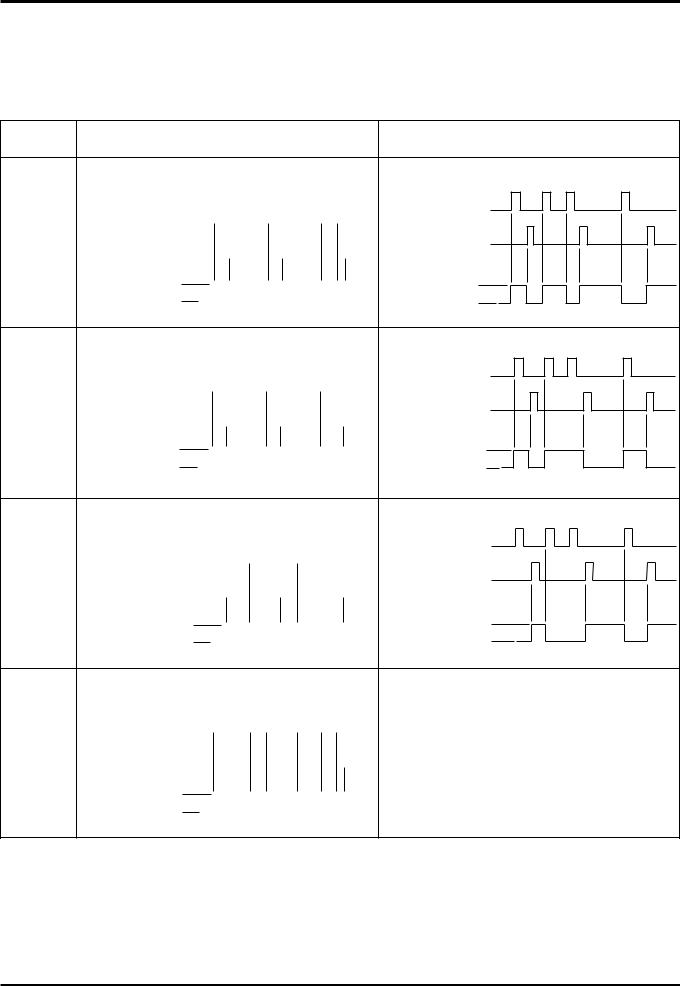
5.1External Control Operating Mode Selection
There are four modes when operating using signals from external equipment.
1.ON/OFF interlock (the chosen function from either external signal or remote control switch has priority)
2.ON interlock
3.OFF interlock
4.External priority ON/OFF interlock
Operating Signal
Mode |
When external signal is level signal. |
When external signal is pulse signal. |
|
(Optional setting) |
|||
|
|
ON/OFF |
External signal |
|
|
|
|
|
|
|
|
|
|
|
|
|
|
|
|
|
|
|
|
|
|
External signal |
|
|
|
|
|
|
|
|
|
|
|
|
|
|
|
|
|
|
|
|
|
|
|
||
inter- |
Remote controller |
|
|
|
|
|
|
|
|
|
|
|
|
|
|
|
|
Remote controller |
||||||
|
|
|
|
|
|
|
|
|||||||||||||||||
|
|
|
|
|
|
|
|
|
|
|
|
|
|
|
|
|
|
|
|
|
|
|
|
[ON/OFF] button pressed |
lock |
[ON/OFF] button pressed |
|
|
|
||||||||||||||||||||
|
|
|
|
|
||||||||||||||||||||
|
Operating Operating |
|
|
|
|
|
|
|
|
|
|
|
|
|
|
Operating Operating |
||||||||
|
|
|
|
|
|
|
|
|
|
|
|
|
|
|||||||||||
|
condition Stopped |
|
|
|
|
|
|
|
|
|
|
|
|
|
|
|
|
condition Stopped |
||||||
|
|
|
|
|
|
|
|
|
|
|
|
|
||||||||||||
ON |
External signal |
|
|
|
|
|
|
|
|
|
|
|
|
|
|
|
|
|
External signal |
||
|
|
|
|
|
|
|
|
|
|
|
|
|
|
|
|
|
Remote controller |
||||
|
|
|
|
|
|
|
|
|
|||||||||||||
|
|
|
|
|
|
|
|
|
|
|
|
|
|
|
|
|
|
|
|||
inter- |
Remote controller |
|
|
|
|
|
|
|
|
|
|
|
|
||||||||
|
|
|
|
|
|
|
|
|
|
|
|
||||||||||
|
|
|
|
|
|
|
|
|
|
|
|
[ON/OFF] button pressed |
|||||||||
lock |
[ON/OFF] button pressed |
|
|
|
|
|
|
|
|
|
|
|
|
|
|
|
|||||
|
Operating |
Operating |
|
|
|
|
|
|
|
|
|
Operating |
Operating |
||||||||
|
|
|
|
|
|
|
|
|
|
|
|
|
|
|
|
||||||
|
condition |
Stopped |
|
|
|
|
|
|
|
|
|
|
condition |
Stopped |
|||||||
|
|
|
|
|
|
|
|
|
|
|
|||||||||||
OFF |
External signal |
|
|
|
|
|
|
|
|
|
|
|
|
|
|
|
|
|
|
|
External signal |
||
|
|
|
|
|
|
|
|
|
|
|
|
|
|
|
|
|
|
|
Remote controller |
||||
|
|
|
|
|
|
|
|
|
|||||||||||||||
|
|
|
|
|
|
|
|
|
|
|
|
|
|
|
|
|
|
|
|
|
|||
inter- |
Remote controller |
|
|
|
|
|
|
|
|
|
|
|
|
|
|
|
|
|
|||||
|
|
|
|
|
|
|
|
|
|
|
|
|
|
|
|||||||||
|
|
|
|
|
|
|
|
|
|
[ON/OFF] button pressed |
|||||||||||||
lock |
[ON/OFF] button pressed |
|
|
|
|
||||||||||||||||||
|
|
|
|
|
|
||||||||||||||||||
|
Operating |
Operating |
|
|
|
|
|
|
|
|
|
|
Operating |
Operating |
|||||||||
|
|
|
|
|
|
|
|
|
|
|
|||||||||||||
|
condition |
Stopped |
|
|
|
|
|
|
|
|
|
|
|
|
|
condition |
Stopped |
||||||
|
|
|
|
|
|
|
|
|
|
||||||||||||||
External |
External signal |
|
|
|
|
|
|
|
|
|
|
|
|
|
|
|
|
|
|
|
|
|
|
|
|
|
|
|
|
|
|
|
|
|
|
|
|
|
|
|
|
|
|||
priority |
|
|
|
|
|
|
|
|
|
|
|
|
|
|
|
|
|
|
|
|
||
|
|
|
|
|
|
|
|
|
|
|
|
|||||||||||
ON/OFF |
Remote controller |
|
|
|
|
|
|
|
|
This mode does not exist. |
||||||||||||
|
|
|
|
|
|
|
|
|||||||||||||||
inter- |
[ON/OFF] button pressed |
|
|
|
|
|
|
|
|
|
|
|||||||||||
|
|
|
|
|
|
|
|
|
|
|||||||||||||
lock |
Operating |
Operating |
|
|
|
|
|
|
|
|
|
|
||||||||||
|
|
|
|
|
|
|
|
|
|
|
||||||||||||
|
condition |
Stopped |
|
|
|
|
|
|
|
|
|
|
|
|
|
|
||||||
Setting Method
When PZ-41SLB-E is used, use the remote controller to set. (Refer to page C-91)
When PZ-41SLB-E is not used, use the DIP switch 5-7,8 to set. (Refer to page C-76)
C-23

5.2Delayed Interlocked Operation
It is possible to delay operation of the Lossnay if an external device is operating. (Energy saving capability.)
<When PZ-41SLB-E is used> (Refer to page C-91, Remote controller to be set)
●Choose from 10, 20, 30, 40, 50, and 60 minute delayed Lossnay operation.
●Delayed operation does not occur if the Lossnay operation was cancelled within the last two hours.
(When turned off for a short time, during a lunch break, for example, if the direction to restart operation is given within two hours, the Lossnay will restart immediately.)
● If an operation button is pressed on the remote controller while the delay timer is operating, the delayed operation is cancelled and normal operation begins.
<When PZ-41SLB-E is not used>
Delays Lossnay operation for 30 minutes.when City Multi or Mr.Slim starts operating or when a external device starts operating. (Refer to page C-74)
5.3Multiple External Device Operation (PZ-60DR-E, PZ-41SLB-E, M-NET)
When there are multiple air conditioners or other external devices
Characteristics |
Ordered parts |
|
Notes |
Lossnay operates at the same time as |
Remote controller |
• |
Can receive level signal, uncharged |
any of the external devices. |
|
|
a-contact external signals. |
|
|
• |
If the external device is a pulse sig- |
|
|
|
nal or charged signal, multiple con- |
|
|
|
nections cannot be made. |
|
|
|
|
System Example
When the Operation Signal is a Uncharged a-contact Level Signal.
(Signal cable between Lossnay and remote controller must be more than 500 m.)
φ 0.65 to 1.2 PVC cable or
0.3 mm2 to 1.25 mm2 strand wire.
|
|
|
Uncharged a-contact |
Uncharged a-contact |
Uncharged a-contact |
||||||||||||||||||
Lossnay |
|
|
|
|
|
|
|
|
|
|
|
|
|
|
|
|
|
|
|
|
|||
|
|
|
Indoor unit of |
|
|
|
|
Indoor unit of |
|
|
|
|
|
Indoor unit of |
|
|
|||||||
|
|
|
air conditioner 1 |
|
|
|
air conditioner 2 |
|
|
|
|
air conditioner 4 |
|
|
|||||||||
|
|
|
Power supply |
Power supply |
|
|
|
|
|
|
|
Power supply |
|
|
|
|
|
|
|
|
Power supply |
||
|
|
|
|
|
|||||||||||||||||||
|
|
|
|
|
|
|
|||||||||||||||||
|
|
|
|
|
|
|
|
|
|
|
|
|
|
|
|
|
|
|
|
|
|
|
|
|
|
|
|
|
|
|
|
|
|
|
|
|
|
|
|
|
|
|
|
|
|
|
|
Lossnay Remote |
Indoor unit |
Indoor unit |
Indoor unit |
controller |
remote controller |
remote controller |
remote controller |
PZ-60DR-E |
|
|
|
* Illustration shows an example when using PZ-60DR-E
C-24
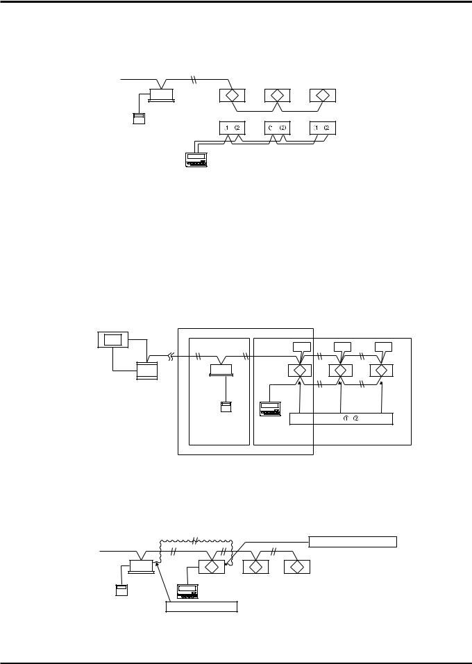
5.4Multiple Lossnay Units Interlocked with One Indoor Unit (M-NET only)
[Example: System 1]
Set the Main/Sub switch of the Lossnay connected to the M-NET transmission cable to “Main,” set the other Lossnay units to “Sub,” and connect 1 and 2 of the Lossnay remote controller (PZ-60DR-E or PZ-41SLB-E) transmission cable terminal (TM4) to the corresponding terminal on the next unit.
M-NET transmission cable |
|
|
Indoor unit |
|
|
TM4 |
TM4 |
TM4 |
MA remote |
|
|
controller |
|
|
Lossnay |
Lossnay |
Lossnay |
(Main) |
(Sub) |
(Sub) |
Lossnay Remote controller |
|
|
PZ-60DR-E or PZ-41SB-E |
|
|
Note:
Make the setting of the first Lossnay unit and the indoor unit to be interlocked.
It is not necessary to set the address or control for other Lossnay units, directly.
Malfunctions of the Lossnay units for sub units will not appear on the remote controller.
[Example: System 2]
When you want to also monitor and manage the Sub set Lossnay malfunctions via a centralized controller, wire all of the TM4 of Lossnays, set the main/sub switch of the Lossnay of the smallest address to “Main”, and set other Lossnays at “Sub.” From the centralized controller, set indoor unit and Lossnays group registration, respectively, and set the interlock with an indoor unit and a Lossnay of the smallest address in a group.
Centralized controller AG-150A
Power supply unit
M-NET |
TB5 |
TB5 |
TB5 |
|||
transmission cable |
||||||
|
|
|
|
|
||
Indoor unit |
Main |
|
Sub |
|
Sub |
|
(001) |
Lossnay |
Lossnay |
Local |
|
Lossnay |
|
|
|
|||||
|
(010) |
(011) |
transmission |
(012) |
||
|
|
|
cable |
|
|
|
MA |
Lossnay |
TM4 |
|
|
|
|
remote |
remote |
|
|
|
|
|
controller |
controller |
|
|
|
|
|
Group1 |
PZ-60DR-E Group2 |
|
|
|
|
|
Interlocked setting
The inside of ( ) is an address number.
[Example: System 3]
Use the Lossnay remote controller to set the indoor units of air conditioner and Lossnay units to separate groups. Both interlocked operation of an indoor unit of air conditioner and Lossnay units can be performed independently by connecting the remote display output for the indoor unit and the external control input for the Lossnay unit.
M-NET |
External control input (TM2) |
|
transmission cable |
||
|
Indoor unit |
Lossnay |
Lossnay |
Lossnay |
|
Lossnay remote controller |
|
|
MA remote |
(PZ-60DR-E) |
|
|
Remote display output |
|
|
|
controller |
|
|
|
Note:
Do not make the setting of the indoor and Lossnay units to be interlocked, because the ventilation switch on the MA remote controller will become invalid, and the error indicator for the Lossnay unit will appear only on the Lossnay remote controller.
C-25
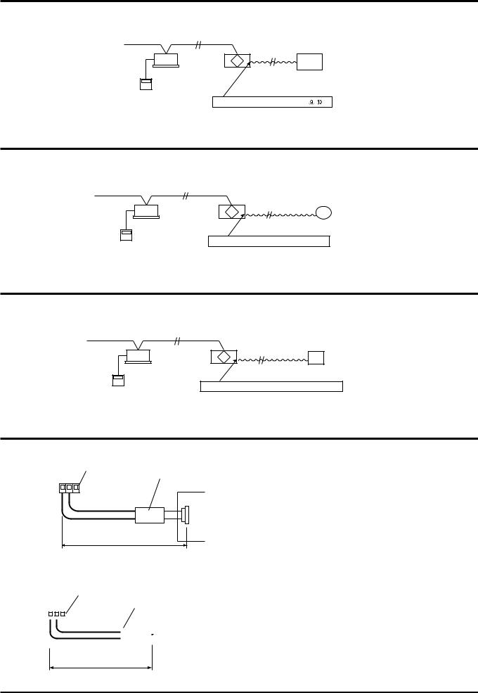
5.5Operation monitor output (Refer to page C-70)
[Example System]
M-NET transmission cable
|
Lossnay |
|
Indoor unit |
Electrically operated damper/ |
|
|
||
|
Booster fan etc. |
|
MA remote |
Operation monitor output (TM4 |
) |
controller |
||
5.6Malfunction monitor output (Refer to page C-69)
[Example System]
M-NET transmission cable
Indoor unit
MA remote controller
Lossnay
Malfunction indicator (Lamp or monitoring unit) Malfunction monitor output (TM3 
 )
)
5.7By-pass operation monitor output (Refer to page C-69)
[Example System]
M-NET transmission cable
Indoor unit
MA remote controller
Lossnay
By-pass operation indicator (Lamp or booster fan etc) By-pass Operation monitor output (TM3
 )
)
5.8Connection Method
1. When using Mitsubishi Mr.Slim air conditioner with MA Remote controller. (Refer to page C-67)
Lossnay External controller input (TM2) |
Slim-Lossnay connection cable |
123 |
(Enclosed accessory) |
|
|
|
CN2L |
|
White |
|
Mr. Slim (Indoor unit) |
|
Red |
Within 500 m |
Printed circuit board |
|
Connect the interlocking cable connector side to CN2L on the circuit board for the indoor Mr.Slim unit, then connect the lead wire side to the 1 and 2. of the input terminal block (TM2) for the Lossnay external controller input. (No polarity)
2. When the external device has a charged operating signal of 12 VDC or 24 VDC. (Refer to page C-68)
Lossnay External control input (TM2)
123 |
|
0.5 mm2 to 1 mm2 sheathed PVC cable |
||||||
|
|
|
|
|
|
|
|
|
|
|
|
|
|
|
External device |
||
|
|
|
|
|
|
|
|
|
|
|
|
|
|
|
|
|
|
|
|
|
|
|
|
|
|
|
|
|
|
|
|
|
|
|
|
12 or 24 VDC
Overall connection extension length
(Follow the operation manual for the external equipment.)
Connect the operating signal (wire) from the external device via the remote output to 1 and 2. on the external control input terminal block (TM2). (No polarity)
C-26

3. When the external device has an uncharged a-contact signal.(Refer to page C-68)
Lossnay External controller input (TM2)
1230.5 mm2 to 1 mm2 sheathed PVC cable External device
Uncharge a-contact
Within 500 m
Connect the operating signal (wire) from the external device via the remote output to 1 and 3 on the external control input terminal block (TM2).
Caution:
●If an optocoupler or any othe type of polar coupler is used at the uncharged a-contact, connect the positive side to 3 and the negative side to 1.
4. Multiple uncharged a-contacts.
Remote output component |
|
|
|
|
|
|
||||||
|
|
|
|
|
|
|
|
External |
|
|
Power |
|
|
|
|
|
|
|
|
|
|
||||
|
|
|
|
|
|
|
|
device |
|
|
|
|
|
|
|
|
|
|
|
|
|
|
|
|
External device |
|
|
|
|
|
|
|
|
|
|
|
|
operation switch |
|
|
|
|
|
|
|
|
|
|
|
Power |
|
|
Lossnay |
|
|
|
External |
|
|
|||||
|
|
|
|
|||||||||
|
|
1 |
|
|
|
device |
|
|
|
|||
External control |
2 |
|
|
|
|
|
|
|
External device |
|||
input (TM2) |
3 |
|
|
|
|
|
|
|
operation switch |
|||
|
|
|
|
|
|
|
|
|
|
|
|
Power |
|
|
|
|
|
|
|
|
External |
|
|
||
|
|
|
|
|
|
|
|
|
|
|||
|
|
|
|
|
|
|
|
device |
|
|
|
|
|
|
|
|
|
|
|
|
|
|
|
|
External device |
|
|
|
|
|
|
|
|
|
|
|
|
operation switch |
|
|
|
|
|
|
|
|
|
|
|
|
|
|
|
|
|
|
|
|
|
|
|
|
Power |
|
|
|
|
|
|
|
|
|
External |
|
|
||
|
|
|
|
|
|
|
|
|
|
|||
|
|
|
|
|
|
|
|
device |
|
|
|
|
|
|
|
|
|
500 m or less |
|
|
|
|
|
External device |
|
|
|
|
|
|
|
|
|
|
|
operation switch |
||
|
|
|
|
|
|
|
|
|
|
|
|
|
Connect the operating signal (wire) from the external device via the remote output to 1 and 3 on the external control input terminal block (TM2).
Caution:
●If an optocoupler or any othe type of polar coupler is used at the uncharged a-contact, connect the positive side to 3 and the negative side to 1.
5. When connect to an Electrically operated damper, or take Operation monitor output.
|
Power Supply |
|
|
|
|
|
|
Monitor output |
|
|
|
||
|
terminal (TM4) |
|
|
|
||
Electrically |
0 |
|
|
|
|
|
operated |
|
|
|
|
|
|
damper |
9 |
|
Contactor rating |
|
||
|
|
|
|
|
||
|
|
|
|
Max |
240 VAC, |
2 A |
|
|
|
|
|
24 VDC, |
2 A |
|
|
|
|
|
||
|
|
|
|
Min |
220 VAC, |
100 mA |
Lamp |
|
|
|
|
5 VDC, |
100 mA |
|
|
|
|
|
|
|
Connect the power supply cable from the Electrically operated damper to 9 and 0 of the monitor output terminal block (TM4) with reference to the wire connection diagram.
Operation monitor output with delay function 1 can be possible. (Refer to function setting 6 (refer to C-74) “Setting for TM4 9 0”).
Note:
●Don’t tighten screws of terminal block with a torque larger than 0.5Nm. It could damage the PCB.
●Response times to external input signals are as shown in the following table.
External Signal |
Response Time |
|
|
Level Signal |
Max. 7 sec. |
|
|
Pulse Signal |
Max. 200 msec |
|
|
6. When take Malfunction monitor output, or take By-pass operation monitor output (Refer to page C-75)
Bypass operation indicator |
|
|
|
|
|
|
Power |
Monitor output terminal |
|
|
|
|
TM3 |
By-pass operation signal |
|||
Lamp or |
Supply |
|
|||
6 |
contactor rating |
|
|||
|
|
||||
monitoring unit |
|
|
|||
|
|
Max |
240 VAC, |
1A |
|
|
|
7 |
|||
|
|
|
24 VDC, |
1A |
|
|
|
|
|
||
Malfunction indicator |
|
8 |
Min |
220 VAC, |
100 mA |
|
|
|
5 VDC, |
100 mA |
|
Malfunction signal
C-27

7. ON/OFF power operation without using the remote controller.
Switch
TM1
Power source for LOSSNAY
Lossnay
TM2
1 2 3
Connect as shown in the wiring diagram to the left.
When the Switch ON, the LOSSNAY unit will begin to operate.
*LOSSNAY FAN speed can be selected (High/Low) through DIP switch 2-4 and 2-5.
*Ventilation mode (LOSSNAY/By-pass) is set to automatic.
5.9When switching High/Low/Extra-Low fan speed externally (when CO2 sensor or other equipment is connected)
Using marketed CO2 sensor, etc., make connection by inserting the optional remote display adaptor (PAC-SA88HA-E) in the connector CN16 (High/Low selector) as shown by the figure.
● To force High fan speed externally
CO2 sensor, etc. |
|
Remote display |
|
|
|
|
||
(When CO2 |
|
adaptor (Optional) |
Lossnay |
|||||
increases: Closed) |
PAC-SA88HA-E |
control board |
||||||
SW1 |
|
Brown 1 |
|
|
|
|
|
|
|
|
|
|
|
|
|
||
|
Red 2 |
|
|
|
|
|
|
|
|
|
Orange 3 |
|
|
|
|
|
|
|
|
Yellow 4 |
|
|
|
|
|
|
|
|
Green 5 |
|
|
|
Fan speed/ |
||
|
|
|
|
|
Ventilation |
|||
SW1: High fan speed operation switch |
|
|
|
|
|
mode selection |
||
|
|
|
|
|||||
Not used. Insulate completely. |
||||||||
(When closed: For High fan speed operation) |
Max wiring length 10 m |
|||||||
When SW1 is “ON”, fan speed of the Lossnay will be set to “High”(Extra-High) regardless of the remote control setting. Use this in such a way that it ventilates at Low or Extra-Low fan speed normally, and when the external sensor detects contamination of indoor air, it changes to High (Extra High) fan speed operation.
● To force Low fan speed externally
CO2 sensor, etc. |
Remote display |
|
|
(When CO2 |
adaptor (Optional) |
Lossnay |
|
increases: Closed) |
PAC-SA88HA-E |
control board |
|
|
Brown 1 |
|
|
SW1 |
Red 2 |
|
|
Orange 3 |
|
|
|
|
|
|
|
|
Yellow 4 |
|
Fan speed/ |
|
|
||
|
Green 5 |
|
|
|
|
Ventilation |
|
|
|
|
mode selection |
SW1: Low fan speed operation switch |
Not used. Insulate completely. |
||
(When closed: For Low fan speed operation) |
Max wiring length 10 m |
||
When SW1 is "ON", fan speed of the Lossnay will be set to “Low” regardless of the remote control setting.
Use this in such a way that it ventilates at High fan speed normally, and when the external sensor detect that the indoor air contamination is low, it changes to Low fan speed operation.
● To force Extra-Low fan speed externally
CO2 sensor, etc. |
Remote display |
|
|
(When CO2 |
adaptor (Optional) |
Lossnay |
|
increases: Closed) |
PAC-SA88HA-E |
control board |
|
|
Brown 1 |
|
|
|
Red 2 |
|
|
SW1 |
Orange 3 |
|
|
Yellow 4 |
|
Fan speed/ |
|
|
|||
|
|
||
|
Green 5 |
|
|
|
|
Ventilation |
|
|
|
|
mode selection |
SW1: Low fan speed operation switch |
Not used. Insulate completely. |
||
(When closed: For Low fan speed operation) |
Max wiring length 10 m |
||
When SW1 is "ON", fan speed of the Lossnay will be set to “Extra-Low” regardless of the remote control setting.
Use this in such a way that it ventilates at High fan speed normally, and when the external sensor detects that the indoor air contamination is low, it changes to Extra-Low fan speed operation.
*For the LGH-150RX5 and LGH-200RX5 types, fan speed of the Lossnay will be “Low”.
C-28
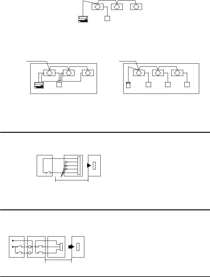
1When using PZ-60DR-E or PZ-41SLB-E to connect multiple Lossnay units
●Connect the sensor to the Lossnay set to “Main”.
●It is not necessary to connect to any Lossnay with the “Sub” setting.
●Connect any sensor, etc., with the external change input to the Lossnay unit set to “Main”.
●Any Lossnay with the “Sub” setting will operate at the same High/Low setting as the Lossnay with the “Main” setting when there is sensor signal input.
Main |
Sub |
Sub |
Lossnay |
Lossnay |
Lossnay |
(Main) |
(Sub) |
(Sub) |
CO2 sensor
PZ-60DR-E or PZ-41SLB-E
2When using M-NET for a group of multiple units
●Even if the units are in the same group, you can only change operation to High/Low for Lossnay units connected to the sensor.
CASE 1 : PZ-60DR-E |
|
|
CASE 2 : PZ-52SF-E |
|
|
Main |
Sub |
Sub |
|
|
|
Lossnay |
Lossnay |
Lossnay |
Lossnay |
Lossnay |
Lossnay |
PZ-60DR-E |
CO2 sensor |
|
PZ-52SF-E |
CO2 sensor |
CO2 sensor CO2 sensor |
|
Group |
|
|
Group |
|
Note:
● When using the M-NET system, the fan speed being input by the sensor signal will not be displayed on the remote controller.
5.10 When switching By-pass externally
Establish the wire connection by inserting the optional remote display adaptor (PAC-SA88HA-E) in the connector CN16 (Ventilation mode selector).
|
Remote display |
Lossnay |
|
|
adaptor (Optional) |
||
|
PAC-SA88HA-E |
control board |
|
|
Brown 1 |
|
|
|
Red 2 |
|
|
|
Orange 3 |
|
|
|
|
|
|
SW1 |
Yellow 4 |
|
Fan speed/ |
|
|||
Green 5 |
|
||
|
|
||
|
|
|
Ventilation |
|
|
|
mode selection |
SW1: Bypass ventilation operation switch |
Not used. Insulate completely. |
||
(When closed: For Bypass ventilation operation) |
Max wiring length 10 m |
||
With SW1 is “ON”, the ventilation mode of Lossnay is changed to the By-pass ventilation regardless of the setting on the remote controller.
*When the outdoor air temperature drops lower than 8°C, it changes to the heat exchanger ventilation. (Display of the remote controller does not change.)
5.11 When using the remote/local switching and the ON/OFF input (level signal)
The remoto controller (PZ-41SLB-E) cannot be used.Insert the optional remote ON/OFF adaptor (PAC-SE55RA-E) in CN32 on the Lossnay control PCB.
Remote control circuit
supply |
SW2 |
|
power |
||
SW1 |
||
Relay |
||
|
Remote ON/OFF
adaptor Lossnay control Relay circuit (PAC-SE55RA-E) board
Orange 1
X |
X |
Red 2 |
|
||
|
|
|
Y |
Y |
Brown 3 |
|
||
|
|
Max wiring length 10 m
SW1: When this is ON, Lossnay cannot turn ON/OFF by the Remote Controller (PZ-60DR-E, PZ-52SF-E).
SW2: When SW1 is ON, Lossnay can be turned ON by setting SW2 at ON or turned OFF by setting SW2 at OFF.
SW1: Remote/local selector switch
SW2: ON/OFF switch
X, Y : Relay (Contactor rating DC 1 mA)
C-29
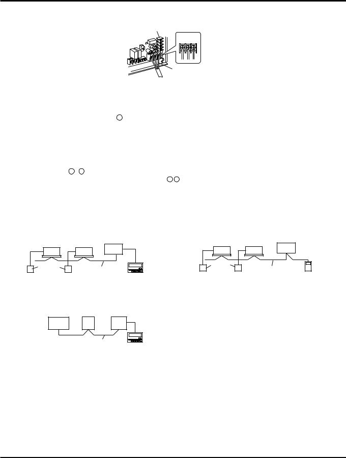
5.12When connecting to the City Multi, Lossnay remote controller (PZ-52SF-E) or Mitsubishi Electric Air-Conditioner Network System
(MELANS)
If centralized control is performed according the wire connection shown in this section, the remote controller (PZ-41SLB-E) cannot be used.
M-NET transmission cable input terminal block
TB5
A B S
Shielded wire
 M-NET transmission cable
● One shielded wire is connected to TB5 S on the PCB on terminal.Address setting is required. (Refer to function setting section.)
M-NET transmission cable: Connect any of the City Multi indoor unit, or Mitsubishi Electric Air-Conditioner Network System (MELANS) - to the Lossnay.
● Connecting positions are different for the Remote Controller PZ-60DR-E and PZ-52SF-E.
PZ-60DR-E:
Connect to TM4 1, 2 on the PCB. (Refer to page C-71 “When connecting with Remote Controller (PZ-60DR-E)”.)
PZ-52SF-E:
Connect to TB5 A , B on the same terminal block as for theM-NET transmission wires.
●Securely connect the M-NET transmission wires to TB5 A B .(No-Polar) Type: (Shielded wire, CVVS/CPEVS)
Wire diameter: 1.25 mm2 to 2.0 mm2
When interlocking with Mitsubishi Free Plan air conditioner
● Incase of PZ-60DR-E |
● Incase of PZ-52SF-E |
|
|||
Indoor unit |
Indoor unit |
Indoor unit |
Indoor unit |
|
|
of air conditioner |
of air conditioner |
of air conditioner |
of air conditioner |
|
|
|
Lossnay |
|
Lossnay |
|
|
MA remote |
M-NET transmission |
MA remote |
M-NET transmission |
|
|
controller |
|
||||
controller |
cable |
cable |
PZ-52SF-E |
||
PZ-60DR-E |
|||||
|
|
|
|
||
When connecting to PZ-60DR-E and MELANS
● Connect the power feeding unit.
(Optional) |
Power |
MELANS |
Lossnay |
supply unit |
M-NET transmission cable
PZ-60DR-E
*Limit the total length of transmission wires no longer than 500 m. Limit the wiring length between Lossnay and the power supply unit (Optional) or the outdoor unit no longer than 200 m.
CAUTION:
●Don’t tighten screws on the terminal block with a torque larger than 0.5 Nm. It may damage the PCB.
●Always use shielded wires only for the M-NET transmission wires, and finish the shield properly.
C-30
 Loading...