


 Loading...
Liftmaster 8550WLB, Wled, WLED-267, 8587W, 8587WL User Manual
...Wi-Fi® Garage Door Openers
Belt Drive Models |
8550W•8550WL•8550WLB•8550WLB-267•8557W |
|
WLED•WLED-267 |
Chain Drive Models |
8587W•8587WL |
FOR RESIDENTIAL USE ONLY |
• Please read this manual and the safety materials |
|
carefully! |
|
• The door WILL NOT CLOSE unless the Protector |
|
System® is connected and properly aligned. |
|
• Periodic checks of the garage door opener are |
|
required to ensure safe operation. |
|
• This garage door opener is ONLY compatible with |
|
myQ® and Security+ 2.0® accessories. |
|
• DO NOT install on a one-piece door if using devices |
|
or features providing unattended close. Unattended |
|
devices and features are to be used ONLY with |
|
sectional doors. |
|
• Attach warning labels to the location indicated on |
|
label. |
|
Register your garage door opener to receive updates and offers from LiftMaster |
SM
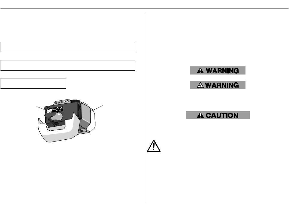
Take a photo of the camera icon including the points ( ).
).
Send it in by texting the photo to 71403 (US)
or visit www.liftmaster.photo (Global)
LiftMaster
300 Windsor Drive
Oak Brook, IL 60523

Table of Contents
Preparation . . . . . . . . . . . . . . . . . . . . . . . . . . . . . . . . . . . . . . . . . . . 3
Carton Inventory Models 8550W, 8550WL, 8550WLB,
8550WLB-267, 8557W, WLED, and WLED-267 . . . . . . . . . . . . . . . . . . . 6 Carton Inventory Models 8587W and 8587WL . . . . . . . . . . . . . . . . . . . . 7
Assembly. . . . . . . . . . . . . . . . . . . . . . . . . . . . . . . . . . . . . . . . . . . . . 8
Models 8550W, 8550WL, 8550WLB, 8550WLB-267
8557W, WLED, and WLED-267 . . . . . . . . . . . . . . . . . . . . . . . . . . . . . . . . 8 Models 8587W and 8587WL. . . . . . . . . . . . . . . . . . . . . . . . . . . . . . . . . . 10
Installation . . . . . . . . . . . . . . . . . . . . . . . . . . . . . . . . . . . . . . . . . . 12 Install the Door Control . . . . . . . . . . . . . . . . . . . . . . . . . . . . . . . . . . 20 Install the Protector System® . . . . . . . . . . . . . . . . . . . . . . . . . . . . . . 22 Power . . . . . . . . . . . . . . . . . . . . . . . . . . . . . . . . . . . . . . . . . . . . . . 26 Adjustments. . . . . . . . . . . . . . . . . . . . . . . . . . . . . . . . . . . . . . . . . . 28 Battery Backup . . . . . . . . . . . . . . . . . . . . . . . . . . . . . . . . . . . . . . . . 31 Operation . . . . . . . . . . . . . . . . . . . . . . . . . . . . . . . . . . . . . . . . . . . 33 Maintenance . . . . . . . . . . . . . . . . . . . . . . . . . . . . . . . . . . . . . . . . . 40 Troubleshooting . . . . . . . . . . . . . . . . . . . . . . . . . . . . . . . . . . . . . . . 41 Accessories . . . . . . . . . . . . . . . . . . . . . . . . . . . . . . . . . . . . . . . . . . 43 Warranty . . . . . . . . . . . . . . . . . . . . . . . . . . . . . . . . . . . . . . . . . . . . 44 Repair Parts
Models 8550W, 8550WL, 8550WLB,
8550WLB-267 and 8557W . . . . . . . . . . . . . . . . . . . . . . . . . . . . . . . . 45-47 Models WLED and WLED-267 . . . . . . . . . . . . . . . . . . . . . . . . . . . . . 48-49 Models 8587W and 8587WL. . . . . . . . . . . . . . . . . . . . . . . . . . . . . . . 50-51
2
Preparation

 Serial Number
Write down the following information for future reference:
myQ Serial Number:
Product S/N:
Date of Purchase:
//
Product S/N
myQ Serial Number
Safety Symbol and Signal Word Review
This garage door opener has been designed and tested to offer safe service provided it is installed, operated, maintained and tested in strict accordance with the instructions and warnings contained in this manual.
When you see these Safety Symbols and Signal Words on the following pages, they will alert you to the possibility of serious injury or death if you do not comply with the warnings that accompany them. The hazard may come from something mechanical or from electric shock. Read the warnings carefully.
Mechanical
Electrical
When you see this Signal Word on the following pages, it will alert you to the possibility of damage to your garage door and/or the garage door opener if you do not comply with the cautionary statements that accompany it. Read them carefully.
WARNING: This product can expose you to chemicals including lead, which are known to the State of California to cause cancer or birth defects or other reproductive harm. For more information go to www.P65Warnings.ca.gov
Unattended Operation
The Timer-to-Close (TTC) feature, the myQ Smartphone Control app, and myQ Garage Door and Gate Monitor are examples of unattended close and are to be used ONLY with sectional doors. Any device or feature that allows the door to close without being in the line of sight of the door is considered unattended close. The Timer-to-Close (TTC) feature, the myQ Smartphone Control, and any other myQ devices are to be used ONLY with sectional doors.
3
Preparation
Before You Connect with Your Smartphone
Monitor and control your garage door from anywhere using the myQ app. You will need:
•Wi-Fi enabled smartphone, tablet or laptop
•Broadband Internet Connection
•Wi-Fi signal in the garage (2.4 Ghz, 802.11b/g/n required)
•Password for your home network (router's main account, not guest network)
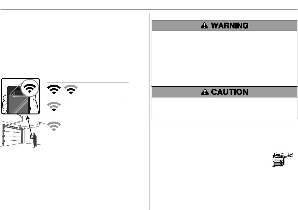
Test the Wi-Fi Signal Strength
Make sure your mobile device is connected to your Wi-Fi network. Hold your mobile device in the place where your garage door opener will be installed and check the Wi-Fi signal strength.
Check Signal Strength. If you see:
Wi-Fi signal is strong.
The garage door opener will connect to your Wi-Fi network.
Wi-Fi signal is weak.
The garage door opener may connect to your Wi-Fi network. If not, try one of the options below to improve the Wi-Fi signal:
No Wi-Fi signal.
The garage door opener will not be able to connect to your Wi-Fi network. Try one of the options below to improve the Wi-Fi signal:
• Move your router closer to the garage door opener to minimize interference from walls and other objects
• Buy a Wi-Fi range extender
For compatible router specifications and help, visit LiftMaster.com/customer-support.
See page 35 to connect the garage door opener to a mobile device.
Check the Door
To prevent possible SERIOUS INJURY orDEATH:
•ALWAYScall a trained doorsystems technician if garage doorbinds, sticks, or is out of balance. An unbalanced garage doormay NOT reverse when required.
•NEVER try to loosen, move oradjust garage door, doorsprings, cables, pulleys, brackets ortheirhardware, ALL of which are underEXTREME tension.
•Disable ALL locks and remove ALL ropes connected to garage doorBEFORE installation and operating garage dooropenerto avoid entanglement.
•DO NOT install on a one-piece doorif using devices orfeatures providing unattended close. Unattended devices and features are to be used ONLYwith sectional doors.
To prevent damage to garage doorand opener:
•ALWAYSdisable locks BEFORE installing and operating the opener.
•ONLYoperate garage dooropenerat 120V, 60 Hz to avoid malfunction and damage.
Before you begin:
1.Disable locks and remove any ropes connected to the garage door.
2.Lift the doorhalfway up. Release the door. If balanced, it should stay in place, supported entirely by its springs.
3.Raise and lowerthe doorto check forbinding orsticking. If yourdoorbinds, sticks, oris out of balance, call a trained door systems technician.
4.Check the seal on the bottom of the door. Any gap between the floorand the bottom of the doormust not exceed 1/4" (6 mm). Otherwise, the safety reversal system may not work properly.
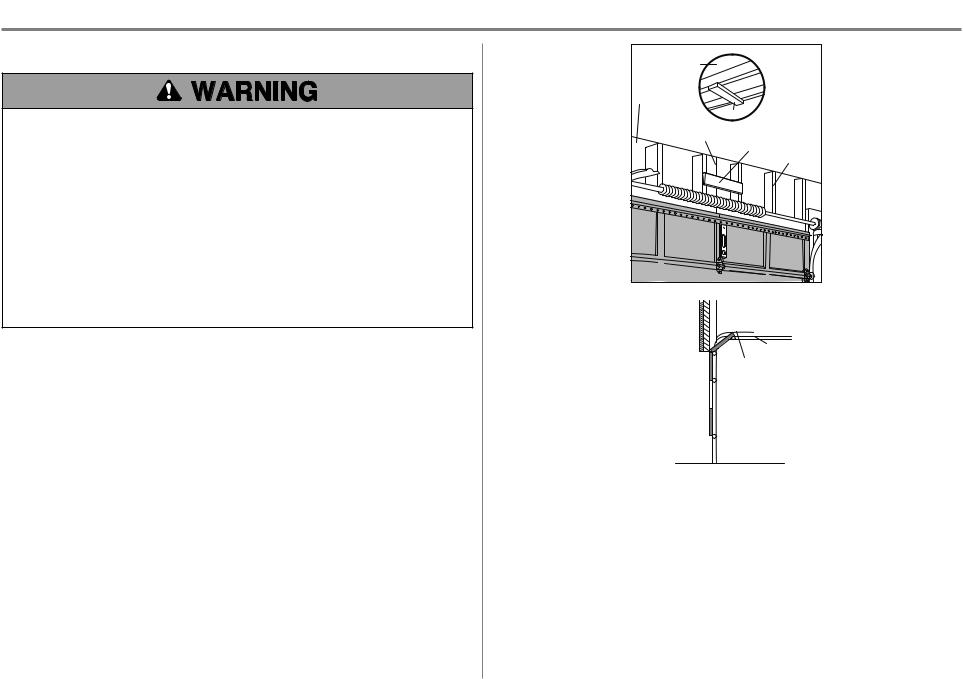
5.The openershould be installed above the centerof the door. If there is a torsion spring orcenterbearing plate in the way of the headerbracket, it may be installed within 4 feet (1.2 m)to the left orright of the doorcenter. See page 11.
Torsion Extension
Spring OR Spring
4

Preparation
Tools Needed
5/32
3/16
5/16 |
7/16 |
1/2
5/8 1/4
7/16 |
9/16 |
|
5
Preparation
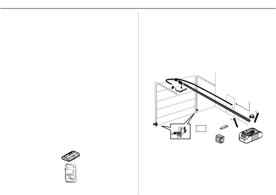
Carton Inventory: Models 8550W, 8550WL, 8550WLB, 8550WLB-267, 8557WL, WLED and WLED-267
Accessories will vary depending on the garage door opener model purchased. Depending on your specific model, other accessories may be included with your garage door opener. The instructions for these accessories will be attached to the accessory and are not included in this manual. The images throughout this manual are for reference and your product may look different.
A.Header bracket
B.Pulley and bracket
C.Door bracket
D.Curved door arm
E.Straight door arm
F.Trolley
G.Emergency release rope and handle
H.Rail
I.Garage door opener
J.Sprocket cover with hex screws
K.Belt
L.Door control
M.White and red/white wire
N.The Protector System®
Safety reversing sensors with white and white/black wire attached: Sending sensor (1), receiving sensor (1), and safety sensor brackets (2)
O.Safety labels and literature
P.Rail grease
Q.Battery (If applicable)
Security+ 2.0® Accessories
893MAX
3- Button Remote Control
880LMW
Smart Control Panel®
Installation
Hex Bolt 5/16"-18 x 7/8" (4) |
Lock Washer 5/16" (4) |
Lag Screw 5/16"-9 x 1-5/8" (2) |
Self-Threading Screw 1/4"-14 x 5/8" (2) |
Clevis Pin 5/16" x 2-3/4" (1) |
Ring Fastener (3) |
Clevis Pin 5/16" x 1-1/4" (1) |
Carriage Bolt 1/4"-20 x 1/2" (2) |
Clevis Pin 5/16" x 1" (1) |
Wing Nut 1/4"-20 (2) |
Nut 5/16"-18 (4) |
|
Door Control Hardware
Screw 6AB x 1" (2) |
Drywall Anchors (2) |
Screw 6-32 x 1" (2) |
|
A 
 B
B
C |
F |
K |
|
|
G |
D |
|
E |
|
|
|
|
|
H |
L
M NOT
PROVIDED
J
|
|
NOT PROVIDED |
N |
O |
P |
|
||
|
|
|
|
Q |
I |
|
|
6
Preparation
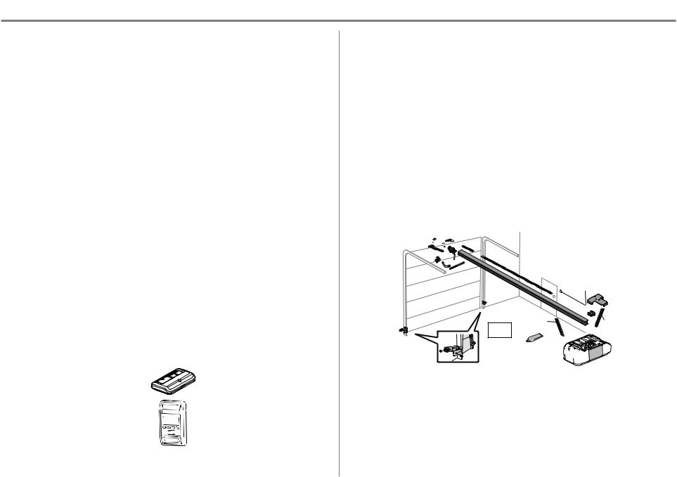
Carton Inventory: Models 8587W and 8587WL
Accessories will vary depending on the garage door opener model purchased. Depending on your specific model, other accessories may be included with your garage door opener. The instructions for these accessories will be attached to the accessory and are not included in this manual. The images throughout this manual are for reference and your product may look different.
Garage Door Opener Assembly
A.Header bracket
B.Pulley and bracket
C.Door bracket
D.Curved door arm
E.Straight door arm
F.Trolley
G.Emergency release rope and handle
H.Rail
I.Garage door opener
J.Chain spreader
K.Chassis support bracket
L.Chain
M.Door control
N.White and red/white wire
O.The Protector System®
Safety reversing sensors with white and white/black wire attached: Sending sensor (1), receiving sensor (1), and safety sensor brackets (2)
P.Safety labels and literature
Q.Rail grease
Security+ 2.0® Accessories
893MAX
3- Button Remote Control
880LMW
Smart Control Panel®
Hardware
Assembly
Chassis Support Bracket Hardware
Screw #8-32 x 3/8" (2)
Hex Bolts 1/4"-20 x 5/8" (2)
Lock Washers (2)
Washered Bolt 5/16"-18 x 1/2" (2)
Installation
Hex Bolt 5/16"-18 x 7/8" (4)
Lag Screw 5/16"-9 x 1-5/8" (2)
Lag Screw 5/16"-18 x 1-5/8" (2)
Clevis Pin 5/16" x 2-3/4" (1)
Clevis Pin 5/16" x 1-1/4" (1)
Clevis Pin 5/16" x 1" (1)
Nut 5/16"-18 (4)
Lock Washer 5/16"-16 (4)
Door Control Hardware
Screw 6AB x 1" (2)
Screw 6-32 x 1" (2)
Chain Spreader Hardware
Screw #8-32 x 3/8" (2)
Rail Hardware
Washered Bolts and Lock Washer (mounted in the top of the garage door opener)
Self-Threading Screw 1/4"-14 x 5/8" (2)
Ring Fastener (3)
Carriage Bolt 1/4"-20 x 1/2" (2)
Wing Nut 1/4"-20 (2)
Hex Bolt 1/4"-20 x 5/8" (2)
Lock Nut 1/4"-20 (2)
Lag Screw 1/4" x 1-1/2" (4)
Drywall Anchors (2)
A


 B
B


C F


 L
L
 G
G
D
E
H
|
|
|
M |
|
|
|
K |
|
|
|
N |
|
|
NOT |
J |
|
|
|
|
|
|
PROVIDED |
|
|
P |
|
NOT |
|
|
PROVIDED |
|
|
|
Q |
|
O |
|
|
|
|
|
|
I 

7
Assembly
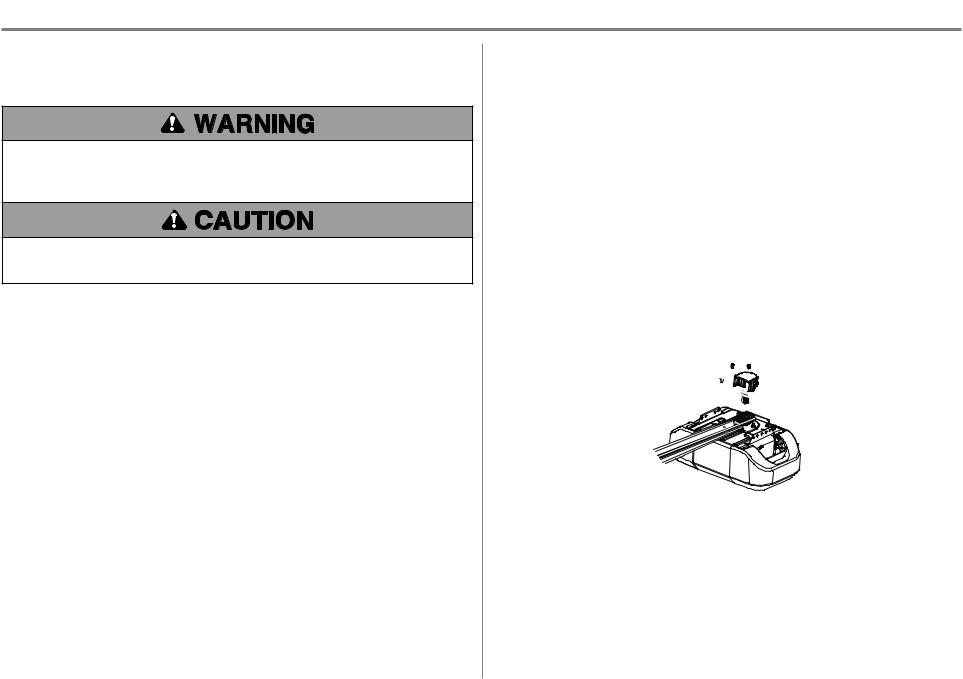
1 Attach the Rail to the Garage Door Opener
Models 8550W, 8550WL, 8550WLB, 8550WLB-267, 8557W, WLED,
and WLED-267
To avoid possible SERIOUS INJURY to finger from moving garage door opener:
•ALWAYS keep hand clear of sprocket while operating opener.
•Securely attach sprocket cover BEFORE operating.
To avoid SERIOUS damage to garage door opener, use ONLY those bolts/fasteners mounted in the top of the opener.
NOTE: ONLY use the bolts removed from the garage door opener. Place the garage door opener on the packing material to prevent scratching.
1.Models 8550W, 8550WL, 8550WLB, 8550WLB-267, WLED, and WLED-267:
Remove the two bolts from the top of the garage door opener.
Model 8557W: Remove bolt and lock nut from the top of the garage door opener.
2.Align the rail and the styrofoam over the sprocket. Cut the tape from the rail, belt, and styrofoam.
3.Models 8550W, 8550WL, 8550WLB, 8550WLB-267, WLED, and WLED-267:
Fasten the rail with the previously removed bolts.
Model 8557W: Fasten the rail with the previously removed washered bolt and lock nut.
4.Position the belt around the garage door opener sprocket.
5.Attach the sprocket cover over the garage door opener sprocket and attach with hex screws.
6.Align the rail and the styrofoam over the sprocket. Cut the tape from the rail, belt, and styrofoam.
7.Position the belt around the garage door opener sprocket.
8.Attach the sprocket cover over the garage door opener sprocket and attach with hex screws.
HARDWARE
Washered Bolt 5/16"-18x1/2" |
Lock Nut |
Hex Screw |
(Mounted in the garage door opener) |
(Mounted in the |
#8x3/8" |
Models 8550W, 8550WL, 8550WLB, |
garage door opener) |
(Packed with the |
8550WLB-267, WLED, and WLED-267 (2) |
Model 8557W (1) |
sprocket cover) |
Model 8557W (1) |
|
|
MODELS 8550W, 8550WL, 8550WLB, 8550WLB-267, WLED, AND WLED-267 |
|
|
Washered Bolt |
Hex Screw |
|
5/16"-18x1/2" |
#8x3/8" |
|
MODEL 8557W
Washered Bolt Lock Nut |
Hex Screw |
5/16"-18x1/2" |
#8x3/8" |
8
Assembly
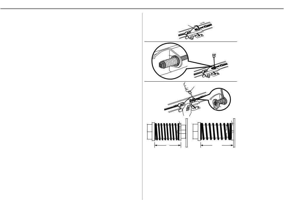
2 Tighten the Belt
Models 8550W, 8550WL, 8550WLB, 8550WLB-267, 8557W, WLED,
and WLED-267
1.By hand, thread the spring trolley nut on the threaded shaft until it is finger tight against the trolley. Do not use any tools.
2.Insert a flathead screwdriver tip into one of the nut ring slots and brace it firmly against the trolley.
3.Tighten the spring trolley nut with an adjustable wrench or a 7/16" open end wrench about a quarter turn until the spring releases and snaps the nut ring against the trolley. This sets the spring to optimum belt tension.
1 |
(To motor unit) |
Spring Trolley Nut
2
Nut ring slot
3
Nut Ring |
Nut Ring |
BEFORE |
AFTER RELEASE |
1" |
1-1/4" |
(2.5 cm) |
(3.18 cm) |
9
Assembly
1 Attach the Rail to the Garage Door Opener
Models 8587W and 8587WL
To avoid SERIOUS damage to garage door opener, use ONLY those bolts/fasteners mounted in the top of the opener.
NOTE: ONLY use the bolts removed from the garage door opener. Place the garage door opener on the packing material to prevent scratching.
1.Remove bolt and lock nut from the top of the garage door opener.
2.Align the rail and the styrofoam over the sprocket. Cut the tape from the rail, chain, and styrofoam.
3.Fasten the rail with the previously removed washered bolt and lock nut.
4.Position the chain around the garage door opener sprocket.
5.Attach the chain spreader to the garage door opener with screws.
6.Guide the chain around the selected groove in the chain spreader, to engage either the 8-tooth or 6-tooth sprocket.
NOTE: The 6-tooth sprocket is for use with Carriage House Doors and the 8-tooth sprocket is for use with regular doors.
HARDWARE
Washered Bolt |
Lock Nut |
|
5/16"-18x1/2" |
||
(Mounted in the |
||
(Mounted in the garage |
||
garage door opener) |
||
door opener) |
||
|
||
Washered Bolt |
Hex Screws 8-32x1" |
|
|
||
5/16"-18x1/2" |
Washers |
|
|
||
Lock |
|
|
Nut |
|
Chain Spreader |
6-Tooth Chain Spreader |
8-Tooth |
|
Sprocket |
Sprocket |
Motor Unit Mounting Plate |
Motor Unit Mounting Plate |
|
10
Assembly
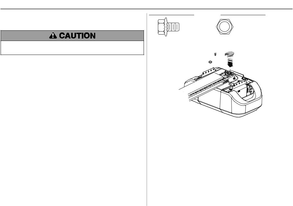
2 Attach the Chassis Support Bracket
Models 8587W and 8587WL
To avoid possible SERIOUS INJURY to finger from moving garage door opener:
•ALWAYS keep hand clear of sprocket while operating opener.
•Securely attach sprocket cover BEFORE operating.
1.Position the chassis support bracket on the unit.
2.Attach the bracket to the rail with 1/4"-20 x 5/8" hex bolts and lock washers. Do not overtighten.
3.Attach the bracket to the opener by inserting a 5/16"-18 x 1/2" washered screw through a hole in each side flange and a matching hole in the bracket. Complete the connection by inserting the #8-32 x 3/8" screw through the back flange and the hole in rail support.
HEX BOLT
LOCK |
1/4"-20X5/8" |
|
|
WASHER |
SCREW |
|
|
|
#8-32X3/8" |
|
WASHERD BOLT |
|
5/16"-18X1/2" |
3 Tighten the Chain
1.Loosen the inner nut and lock washer on the trolley threaded shaft.
2.Tighten the outer nut until the chain is a 1/2" above the base of the rail at the midpoint of the rail.
3.Re-tighten the inner nut.
Slack in the chain is normal when the door is closed. No readjustment is necessary.
1/2" (13 MM)
11
Installation
IMPORTANT INSTALLATION INSTRUCTIONS
To reduce the risk of SEVERE INJURY or DEATH:
1.READ AND FOLLOW ALL INSTALLATION WARNINGS AND INSTRUCTIONS.
2.Install garage door opener ONLY on properly balanced and lubricated garage door. An improperly balanced door may NOT reverse when required and could result in SEVERE INJURY or DEATH.
3.ALL repairs to cables, spring assemblies and other hardware MUST be made by a trained door systems technician BEFORE installing opener.
4.Disable ALL locks and remove ALL ropes connected to garage door BEFORE installing opener to avoid entanglement.
5.Where possible, install the door opener 7 feet (2.13 m) or more above the floor.
6.Mount the emergency release within reach, but at least 6 feet (1.83 m) above the floor and avoiding contact with vehicles to avoid accidental release.
7.NEVER connect garage door opener to power source until instructed to do so.
8.NEVER wear watches, rings or loose clothing while installing or servicing opener. They could be caught in garage door or opener mechanisms.
9. Install wall-mounted garage door control:
•within sight of the garage door.
•out of reach of small children at a minimum height of 5 feet (1.5 m)above floors, landings, steps orany otheradjacent walking surface.
•away from ALL moving parts of the door.
10.Place entrapment warning label on wall next to garage doorcontrol in a prominent location.
11.Place emergency release/safety reverse test label in plain view on inside of garage door.
12.Upon completion of installation, test safety reversal system. Door MUST reverse on contact with a 1-1/2" (3.8 cm)high object (ora 2x4 laid flat)on the floor.
13.DO NOT install on a one-piece doorif using devices orfeatures providing unattended close. Unattended devices and features are to be used ONLYwith sectional doors.
12
Installation
1 Determine the Header Bracket Location
To prevent possible SERIOUS INJURY or DEATH:
•Header bracket MUST be RIGIDLY fastened to structural support on header wall or ceiling, otherwise garage door might NOT reverse when required. DO NOT install header bracket over drywall.
•Concrete anchors MUST be used if mounting header bracket or 2x4 into masonry.
•NEVER try to loosen, move or adjust garage door, springs, cables, pulleys, brackets, or their hardware, ALL of which are under EXTREME tension.
•ALWAYS call a trained door systems technician if garage door binds, sticks, or is out of balance. An unbalanced garage door might NOT reverse when required.
•DO NOT enable the Timer-to-Close functionality if operating either one-piece or swinging garage doors. To be enabled ONLY when operating a sectional door.
Close the door and mark the inside vertical centerline of the garage door.
Extend the line onto the header wall above the door. You can fasten the header bracket within 4 feet (1.22 m) of the left or right of the door center only if a torsion spring or center bearing plate is in the way; or you can attach it to the ceiling when clearance is minimal. (It may be mounted on the wall upside down if necessary, to gain approximately 1/2" (1 cm). If you need to install the header bracket on a 2x4 (on wall or ceiling), use lag screws (not provided) to securely fasten the 2x4 to structural supports.
Open your door to the highest point of travel as shown. Draw an intersecting horizontal line on the header wall 2" (5 cm) above the high point. This height will provide travel clearance for the top edge of the door.
NOTE: If the total number of inches exceeds the height available in your garage, use the maximum height possible, or refer to page 14 for ceiling installation.
Unfinished |
|
OPTIONAL |
|
CEILING |
|
Ceiling |
|
|
|
MOUNT FOR |
|
|
|
|
Header Wall |
|
HEADER |
|
BRACKET |
|
|
|
|
|
2x4 |
|
Vertical Centerline |
|
|
of Garage Door |
|
Structural |
|
2x4 |
|
|
Supports |
|
|
|
Level 
 (Optional)
 Header Wall


 2" (5 cm)
Track
Highest Point
of Travel
 Door
Door
SECTIONAL DOOR WITH CURVED TRACK
13
Installation
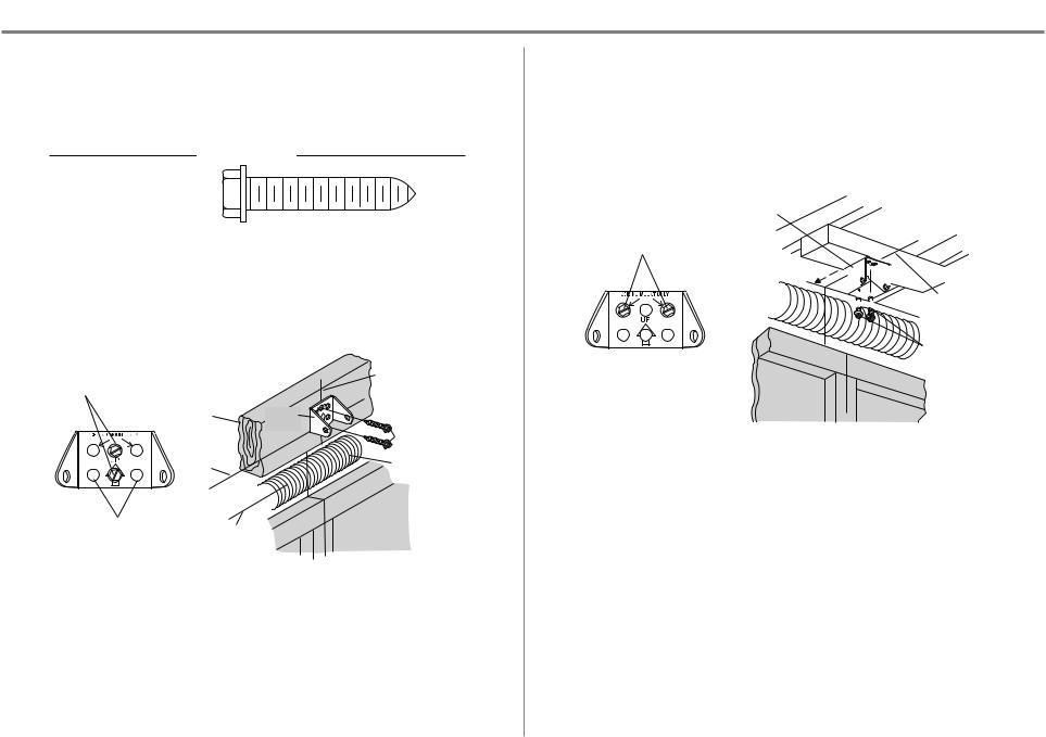
2 Install the Header Bracket
You can attach the header bracket either to the wall above the garage door, or to the ceiling. Follow the instructions which will work best for your particular requirements. Do not install the header bracket over drywall. If installing into masonry, use concrete anchors (not provided).
HARDWARE
LAG SCREW 5/16"-9X1-5/8"
OPTION A - WALL INSTALLATION
1.Center the bracket on the vertical centerline with the bottom edge of the bracket on the horizontal line as shown (with the arrow pointing toward the ceiling).
2.Mark the vertical set of bracket holes (do not use the holes designated for ceiling mount). Drill 3/16" pilot holes and fasten the bracket securely to a structural support with lag screws.
|
|
(Header Wall) |
Vertical |
|
|
|
|
Wall Mount |
|
|
Centerline of |
|
|
Garage Door |
|
|
|
|
|
|
2x4 Structural |
|
|
|
Support |
Header |
|
|
|
Bracket |
|
|
|
|
Lag Screw |
|
Horizontal |
|
5/16"-9 x 1-5/8" |
|
|
|
|
|
Line |
|
Door Spring |
|
|
|
|
Optional |
|
|
(Garage Door) |
Highest Point of |
|
||
Mounting |
|
||
Garage Door |
|
|
|
Holes |
|
|
|
Travel |
|
|
|
|
|
|
|
OPTION B - CEILING INSTALLATION
1.Extend the vertical centerline onto the ceiling as shown.
2.Centerthe bracket on the vertical mark, no more than 6" (15 cm)from the wall. Make sure the arrow is pointing toward the wall. The bracket can be mounted flush against the ceiling when clearance is minimal.
3.Mark the side holes. Drill 3/16" pilot holes and fasten bracket securely to a structural support with the hardware provided.
Header |
(Finished Ceiling) |
|
Bracket |
||
|
Ceiling Mounting Holes
6" (15 cm)
Maximum 


Door Spring 


 Vertical
Centerline of
Garage Door
Lag Screw 5/16"-9 x 1-5/8"
(Header Wall)
(Garage Door)
14
Installation
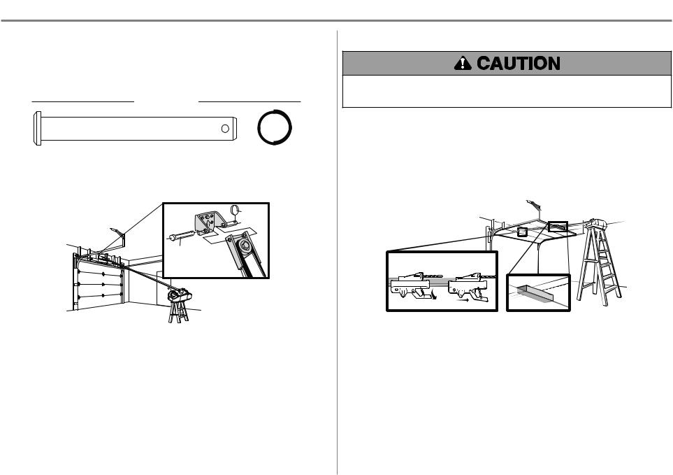
3 Attach the Rail to the Header Bracket
1.Align the rail with the header bracket. Insert the clevis pin through the holes in the header bracket and rail. Secure with the ring fastener.
NOTE: Use the packing material as a protective base for the garage door opener.
HARDWARE
Clevis Pin 5/16" x 2-3/4" |
Ring Fastener |
Ring |
Fastener |
Clevis Pin |
5/16" X 2-3/4" |
4 Position the Garage Door Opener
To prevent damage to garage door, rest garage door opener rail on 2x4 placed on top section of door.
1.Remove the packing material and lift the garage door opener onto a ladder.
2.Fully open the door and place a 2x4 (laid flat) under the rail.
A 2x4 is ideal for setting the distance between the rail and the door. If the ladder is not tall enough you will need help at this point. If the door hits the trolley when it is raised, pull the trolley release arm down to disconnect the inner and outer trolley. Slide the outer trolley toward the garage door opener. The trolley can remain disconnected until instructed.
CONNECTED DISCONNECTED
15
Installation
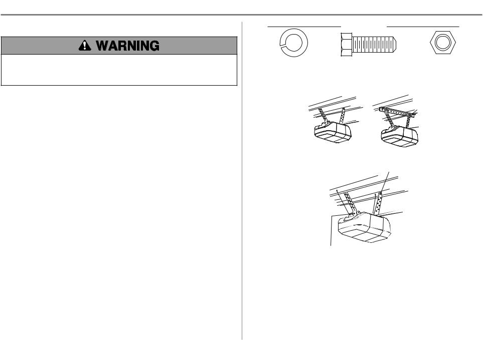
5 Hang the Garage Door Opener
To avoid possible SERIOUS INJURY from a falling garage door opener, fasten it SECURELY to structural supports of the garage. Concrete anchors MUST be used if installing ANY brackets into masonry.
Hanging your garage door opener will vary depending on your garage. Two representative installations are shown. Yours may be different. Hanging brackets should be angled (Figure 1) to provide rigid support. On finished ceilings (Figure 2), attach a sturdy metal bracket to structural supports before installing the opener. This bracket and fastening hardware are not provided.
1.Measure the distance from each side of the motor unit to the structural support.
2.Cut both pieces of the hanging bracket to required lengths.
3.Drill 3/16" pilot holes in the structural supports.
4.Attach one end of each bracket to a support with 5/16"-18 x 1-7/8" lag screws (not provided).
5.Fasten the opener to the hanging brackets with 5/16"-18 x 7/8" hex bolts, lock washers and nuts.
6.Check to make sure the rail is centered over the door (or in line with the header bracket if the bracket is not centered above the door).
7.Remove the 2x4. Operate the door manually. If the door hits the rail, raise the header bracket.
NOTE: DO NOT connect power to opener at this time.
HARDWARE
Lock Washer 5/16" |
Hex Bolt 5/16"- 18x7/8" |
Nut 5/16"-18 |
|
FIGURE 1 |
|
FIGURE 2 |
|
Unfinished Ceiling |
Finished Ceiling |
|
|
Not Provided
FIGURE 3 |
(Not Provided) |
|
Lag Screws |
|
5/16"- 18x1-7/8" |
Measure
Distance
Hex Bolt 5/16"- 18x7/8", Lock Washer 5/16", Nut 5/16"-18
16
Loading...