


Wall Mount Wi-Fi® Garage Door Opener
Model 8500W
For Residential Use
Install On Sectional Doors With Torsion Assemblies Only
This product is intended for installation only by trained garage door technicians. This product may require adjustments to door springs and/or track configurations. This product is not intended for use on low headroom tracks with outside pickup drum or garage doors utilizing extension springs.
•Please read this manual and the enclosed safety materials carefully!
•The door WILL NOT CLOSE unless the Protector System® and cable tension monitor are connected and properly aligned.
•Periodic checks of the garage door opener are required to ensure safe operation.
•The model number is located on the front cover of the opener.
•This garage door opener is ONLY compatible with MyQ® and Security+ 2.0® accessories.
•Attach warning labels to the location indicated on label.
Register your garage door opener to receive updates and offers from LiftMaster
|
Take a photo of the |
SM |
camera icon including |
|
the points ( ). |
Send it in by texting the photo to 71403 (US) or visit www.liftmaster.photo (Global)
LiftMaster
300 Windsor Drive
Oak Brook, IL 60523

Table of Contents |
|
MYQ SERIAL NUMBER |
2 |
UNATTENDED OPERATION |
2 |
INTRODUCTION |
2 |
Safety Symbol and Signal Word Review...... |
2 |
Planning ........................................................ |
3 |
Before You Connect with Your Smartphone 4 |
|
Preparing Your Garage Door ........................ |
5 |
Tools Needed ................................................ |
5 |
Carton Inventory ........................................... |
6 |
Included Accessories.................................... |
6 |
Hardware....................................................... |
6 |
Additional Items You May Need ................... |
6 |
ASSEMBLY |
7 |
Attach the Collar to the |
|
Garage Door Opener ..................................... |
7 |
Attach Mounting Bracket to |
|
Garage Door Opener ..................................... |
8 |
INSTALLATION |
8 |
Position and Mount the |
|
Garage Door Opener ..................................... |
9 |
Attach the Emergency Release Rope |
|
and Handle .................................................. |
10 |
Install Automatic Door Lock ....................... |
10 |
Attach the Cable Tension |
|
Monitor (Required) ..................................... |
11 |
Install the Door Control |
|
(Smart Control Panel®)............................... |
12 |
Install MyQ® Remote LED Light ................. |
13 |
Install the Protector System® .................... |
14 |
Connect Power............................................ |
17 |
Install the Battery Backup ........................... |
19 |
ADJUSTMENT |
20 |
Program the Travel ..................................... |
20 |
Test the Safety Reversal System ................ |
21 |
Test the Protector System® ....................... |
21 |
Test Cable Tension Monitor........................ |
22 |
Test Automatic Door Lock.......................... |
22 |
To Open the Door Manually........................ |
22 |
OPERATION |
23 |
Using Your Garage Door Opener................ |
24 |
Connect with Your Smartphone ................. |
25 |
Using the Door Control............................... |
26 |
PROGRAMMING |
28 |
893MAX Remote Control............................ |
28 |
Reprogramming MyQ® Remote |
|
LED Light..................................................... |
29 |
To Erase the Memory.................................. |
29 |
HomeLink® .................................................. |
30 |
MAINTENANCE |
31 |
Care of Your Garage Door Opener.............. |
31 |
TROUBLESHOOTING |
32 |
Diagnostic Chart.......................................... |
32 |
Additional Troubleshooting......................... |
33 |
REPAIR PARTS |
35 |
Installation Parts ......................................... |
35 |
Garage Door Opener Assembly Parts......... |
36 |
CONTACT INFORMATION |
36 |
ACCESSORIES |
37 |
WARRANTY |
38 |
Automatic Garage Door Opener |
|
Safety & Maintenance Guide |
39 |
MyQ® Serial Number
Write down the following information for future reference:
MyQ® Serial Number:
Product S/N: |
Serial Numbers |
Date of Purchase:
Unattended Operation
The Timer-to-Close (TTC) feature, the MyQ® Smartphone Control app, and MyQ® Garage Door and Gate Monitor are examples of unattended close and are to be used ONLY with sectional doors. Any device or feature that allows the door to close without being in the line of sight of the door is considered unattended close. The Timer-to-Close (TTC) feature, the MyQ® Smartphone Control, and any other MyQ® devices are to be used ONLY with sectional doors.
MyQ Remote LED Light must be installed to enable use of Timer To Close or MyQ Smartphone Control of the door.
Introduction
Safety Symbol and Signal Word Review
This garage door opener has been designed and tested to offer safe service provided it is installed, operated, maintained and tested in strict accordance with the instructions and warnings contained in this manual.
When you see these Safety Symbols and Signal Words on the following pages, they will alert you to the possibility of serious injury or death if you do not comply with the warnings that accompany them. The hazard may come from something mechanical or from electric shock. Read the warnings carefully.
When you see this Signal Word on the following pages, it will alert you to the possibility of damage to your garage door and/or the garage door opener if you do not comply with the cautionary statements that accompany it. Read them carefully.
Mechanical
Electrical
WARNING: This product can expose you to chemicals including lead, which are known to the State of California to cause cancer or birth defects or other reproductive harm. For more information go to www.P65Warnings.ca.gov
2

Introduction
Planning
Survey your area to see if any of the conditions below apply to your installation. Depending on your requirements, additional materials may be required.
THIS DOOR OPENER IS COMPATIBLE WITH:
•Doors that use a torsion bar and springs. The torsion bar must be 1" (2.5 cm) diameter. NOT compatible with reverse wound drums.
•4-6" (10-15 cm) drums, not to be used on tapered drums over 6" (15 cm).
•High lift (up to 54" (137.2 cm) high) and standard lift sectional doors up to 14 ft. (4.3 m) high.
•Doors up to 18 ft. (5.5 m) wide.
•Doors up to 180 sq. ft. (16.7 sq. m).
Review or inspect proposed installation area. The door opener can be installed on the left or right side of door. Select the side that meets the requirements listed below.
NOTE: Inspect the torsion bar while the door is raised and lowered. It is important that there is no noticeable movement up and down or left and right. If the movement is not corrected, the life of the garage door opener will be greatly reduced.
a.Must have minimum of 2.5" (6.4 cm) between the wall and the center of the torsion bar.
b.Must have minimum of 3" (7.6 cm) between the ceiling and the center of torsion bar.
c.Must have minimum of 8.5" (21.6 cm) between the side wall (or obstruction) and the end of torsion bar.
d.The torsion bar must extend at least 1.5" (3.81 cm) past the bearing. This may vary depending on your installation requirements.
e.An electric outlet is required within 6 ft. (1.83 m) of the installation area. If outlet does not exist, contact a qualified electrician.
f.Depending upon building construction, extension brackets or wood blocks may be needed to install safety reversing sensors and cable tension monitor.
g.Alternate floor mounting of the safety reversing sensors will require hardware (not provided).
h.Check the seal on the bottom of the door. Any gap between the floor and the bottom of the door must not exceed 1/4 inch (6 mm). Otherwise, the safety reversal system may not work properly.
|
b 3" |
c (21.68.5" |
(7.6 cm) |
cm) |
|
d |
a |
Torsion bar |
2.5" |
Torsion |
Wall or |
(6.4 cm) |
bar |
|
MyQ® Remote |
|
obstruction |
|
|
|
|
LED Light |
e |
Door spring |
|
Automatic 


 door lock


 g
g 

Safety 


 reversing


sensor
f |
h |
3

Introduction
Before You Connect with Your Smartphone
Monitor and control your garage door from anywhere using the MyQ® app.
BEFORE YOU BEGIN:
You will need:
•Wi-Fi enabled smartphone, tablet or laptop
•Broadband Internet Connection
•Wi-Fi signal in the garage (2.4 Ghz, 802.11b/g/n required)
•Password for your home network (router's main account, not guest network)
TEST THE WI-FI SIGNAL STRENGTH
Make sure your mobile device is connected to your Wi-Fi network. Hold your mobile device in the place where your garage door opener will be installed and check the Wi-Fi signal strength.
Check Signal Strength. If you see:
Wi-Fi signal is strong.
The garage door opener will connect to your Wi-Fi network.
Wi-Fi signal is weak.
The garage door opener may connect to your Wi-Fi network. If not, try one of the options below to improve the Wi-Fi signal:
No Wi-Fi signal.
The garage door opener will not be able to connect to your Wi-Fi network. Try one of the options below to improve the Wi-Fi signal:
•Move your router closer to the garage door opener to minimize interference from walls and other objects
•Buy a Wi-Fi range extender
For compatible router specifications and help, visit WiFiHelp.LiftMaster.com. See page 25 to connect the garage door opener to a mobile device.
4
Introduction
Preparing Your Garage
Door
BEFORE YOU BEGIN:
•Disable locks.
•Remove any ropes connected to the garage door.
Complete the following test to make sure the garage door is balanced and is not sticking or binding:
1.Lift the door halfway up. Release the door. If balanced, it should stay in place, supported entirely by its springs.
2.Raise and lower the door to check for binding or sticking.
3.Doors heavier than 650 lbs. should NOT open or fall rapidly.
If your door binds, sticks, or is out of balance, call a trained door systems technician.
Sectional Door
To prevent possible SERIOUS INJURY or DEATH:
•ALWAYS call a trained door systems technician if garage door binds, sticks, or is out of balance. An unbalanced garage door may NOT reverse when required.
•NEVER try to loosen, move or adjust garage door, door springs, cables, pulleys, brackets or their hardware, ALL of which are under EXTREME tension.
•Disable ALL locks and remove ALL ropes connected to garage door BEFORE installing and operating garage door opener to avoid entanglement.
•This opener system is equipped with an unattended operation feature. The door could move unexpectedly. NO ONE SHOULD CROSS THE PATH OF THE MOVING DOOR.
To prevent damage to garage door and opener:
•ALWAYS disable locks BEFORE installing and operating the opener.
•ONLY operate garage door opener at 120V, 60 Hz to avoid malfunction and damage.
SPECIFICATIONS
Volts . . . . . . . . . . . . . . . . . . . . . . . . . . . . . . . . . . . . . . . . . . . .120 Vac - 60 Hz, ONLY Current . . . . . . . . . . . . . . . . . . . . . . . . . . . . . . . . . . . . . . . . . . . . . . . . . . . . . 1.5 AMP LED Light Current (independently powered) . . . . . . . . . . . . . . . . . . . . . . . . 0.2 AMPS
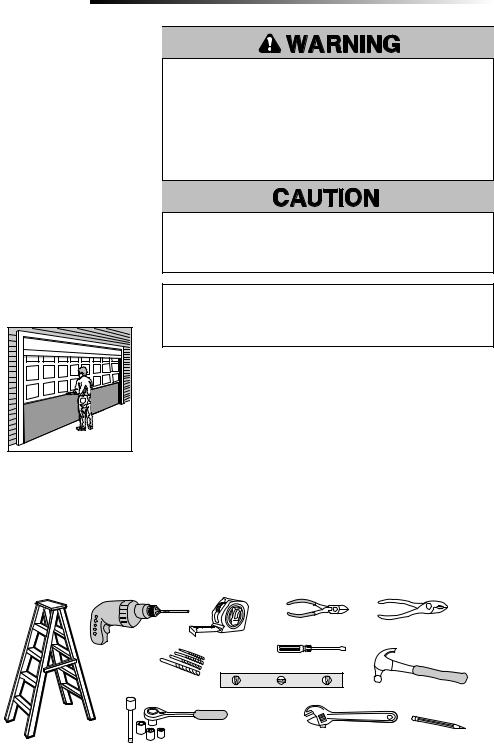
Tools Needed
During assembly, installation and adjustment of the garage door opener, instructions will call for hand tools as illustrated below.
|
|
Wire Cutters |
Pliers |
Drill |
Tape Measure |
|
|
|
|
Screwdriver |
|
5/32", 3/16", 5/16" |
|
|
|
and 3/4" Drill Bits |
|
Claw Hammer |
|
|
Level |
|
|
|
|
|
Pencil |
Stepladder |
1/4", 5/16", and 3/8" Sockets |
Adjustable End Wrench |
|
|
and Wrench with 6" Extension |
||
|
|
|
|
5
Introduction
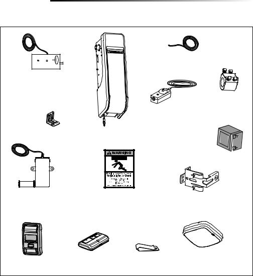
Carton Inventory
If anything is missing, carefully check the packing material.
2 Conductor Bell Wire
White and White/Red
Automatic Garage Door Lock Model 841LM with 2-Conductor White and White/Black Bell Wire with Connector
NOTE: Older model 24V door locks are incompatible
|
|
The Protector System® |
|
|
|
(2) Safety Reversing Sensors |
|
|
|
(1 Sending Sensor and |
|
|
|
1 Receiving Sensor) with |
|
Mounting Bracket |
Garage Door Opener |
2-Conductor White and |
|
White/Black Bell Wire attached |
|||
|
|
Collar with Set Screws
Battery Model 485LM
Cable Tension Monitor with |
Safety Labels |
Safety Reversing Sensor Bracket (2) |
|
2-Conductor Green/White Bell Wires |
and Literature |
||
|
Included Accessories
|
3-Button Premium |
Remote Control |
MyQ® Remote LED Light |
|
|
Model 827LM |
|||
Smart Control Panel® |
Remote Control |
|||
Visor Clip |
||||
(Garage Door Opener Light) |
||||
Model 880LMW |
Model 893MAX (1) |
|
||
|
with Hardware Bag |
|||
|
|
|
Hardware
Screw #10-32 (2) |
Screw 8-32x1" (2) |
Screw 14-10x2" (4) |
Screw 6ABx1-1/4" (2) |
Handle |
Drywall Anchor (2) |
Rope |
Screw 6-32x1" (2) |
Screw 1/4"-20x1/2" (2) |
Carriage Bolt 1/4"-20x1/2" (2) |
Drywall Anchor (Screw-In) (2) |
Wing Nut 1/4"-20 (2) |
Additional Items You May Need
Extension brackets (Model 041A5281-1) |
Fastening hardware: Alternate floor |
or wood blocks: Depending upon garage |
mounting of the safety reversing sensor |
construction, extension brackets or wood |
will require hardware not provided. |
blocks may be needed to install the safety |
|
reversing sensor. |
|
REMOTE LIGHT HARDWARE:
MyQ® Remote LED Light Model 827LM Drywall Anchor (Screw-In) (2)
Screw #6x1" (2)
90˚ connector for cable conduit or flex cable adapter: Required for permanent wiring.
6

Assembly
1 Attach the Collar to the Garage Door Opener
To avoid installation difficulties, do not run the garage door garage door opener until instructed to do so.
The garage door opener can be installed on either side of the door (see Planning section page 3). The illustrations shown are for installation on the left side.
1.Loosen the set screws.
2.Attach collar to the garage door opener motor shaft. The side of the collar with the larger hole should be placed on the motor shaft. Ensure that the collar is seated all the way on motor shaft until stop is reached.
3.Position the collar so the screws are facing out and are accessible when attached to the torsion bar.
4.Securely tighten the 2 square head set screws closest to the motor shaft by turning the screws 1/4 - 1/2 turn after making contact with the motor shaft.
To prevent possible SERIOUS INJURY or DEATH, the collar MUST be properly tightened. The door may NOT reverse correctly or limits may be lost due to collar slip.
Motor |
|
Shaft |
Collar |
|
Set
Screws
7
Assembly
2 Attach Mounting Bracket to Garage Door Opener
1.Loosely attach slotted side of mounting bracket to the same side of the garage door opener as the collar, using screws provided.
NOTE: Do not tighten screws until instructed.
Socket Wrench
HARDWARE
Screw #10-32 (2)
Installation
IMPORTANT INSTALLATION INSTRUCTIONS
To reduce the risk of SEVERE INJURY or DEATH:
1.Read and follow all warnings and instructions.
2.Install garage door opener ONLY on properly balanced and lubricated garage door. An improperly balanced door may NOT reverse when required and could result in SEVERE INJURY or DEATH.
3.ALL repairs to cables, spring assemblies and other hardware MUST be made by a trained door systems technician BEFORE installing opener.
4.Disable ALL locks and remove ALL ropes connected to garage door BEFORE installing opener to avoid entanglement.
5.Where possible, install the door opener 7 feet (2.13 m) or more above the floor.
6.Mount the emergency release within reach, but at least 6 feet (1.83 m) above the floor and avoiding contact with vehicles to avoid accidental release.
7.NEVER connect garage door opener to power source until instructed to do so.
8.NEVER wear watches, rings or loose clothing while installing or servicing opener. They could be caught in garage door or opener mechanisms.
9.Install wall-mounted garage door control:
•within sight of the garage door.
•out of reach of small children at a minimum height of 5 feet (1.53 m) above floors, landings, steps or any other adjacent walking surface.
•away from ALL moving parts of the door.
10.Install the emergency release marking. Attach the marking on or next to the emergency release. Install the entrapment warning placard next to the door control in a prominent location.
11.Place emergency release/safety reverse test label in plain view on inside of garage door.
12.Upon completion of installation, test safety reversal system. Door MUST reverse on contact with a 1-1/2" (3.8 cm) high object (or a 2x4 laid flat) on the floor.
13.To avoid SERIOUS PERSONAL INJURY or DEATH from electrocution, disconnect ALL electric and battery power BEFORE performing ANY service or maintenance.
14.SAVE THESE
INSTRUCTIONS.
8
Installation
1 Position and Mount the Garage Door Opener
NOTE: For additional mounting options refer to the accessories page.
1.Close the garage door completely.
2.Slide the garage door opener onto the end of the torsion bar. If the torsion bar is too long or damaged, you may need to cut the torsion bar.
Ensure the collar does NOT touch the bearing.
3.Use a level to position and vertically align the garage door opener. Verify the mounting bracket is located on a solid surface such as wood, concrete or door/flag bracket. If installing on drywall, the mounting bracket MUST be attached to a stud.
4.When the garage door opener is properly aligned, mark the mounting bracket holes. If necessary, tighten collar screws on the torsion bar to hold garage door opener in place while marking holes.
NOTE: The garage door opener does not have to be flush to wall.
5.Remove the garage door opener from torsion bar. Drill 3/16 inch pilot holes at the marked locations. Drill through metal door rail plates if necessary.
6.Slide the garage door opener back onto the torsion bar until pilot holes align with bracket.
7.Tighten the 2 square head set screws on the torsion bar. For a hollow torsion bar, tighten screws 3/4 - 1 full turn after making contact with the bar. For a solid shaft torsion bar, tighten screws 1/4 - no more than 1/2 turn after making contact with the shaft. If installing on a keyed torsion bar, DO NOT tighten the screws into the keyway.
8.Secure the mounting bracket to the wall and to the garage door opener. Use the 14-10 x 2" screws to secure the mounting bracket to the wall.
.25" (.6 cm) min. space between
bearing and
collar
Collar
Bearing Plate
Torsion Bar
To prevent possible SERIOUS INJURY or DEATH:
•Concrete anchors MUST be used if mounting bracket into masonry.
•NEVER try to loosen, move or adjust garage door, springs, cables, pulleys, brackets or their hardware, ALL of which are under EXTREME tension.
•ALWAYS call a trained door systems technician if garage door binds, sticks or is out of balance. An unbalanced garage door might NOT reverse when required.
•Garage door opener MUST be mounted at a right angle to the torsion bar to avoid premature wear on the collar.
HARDWARE
Screw
14-10 x 2" (2)
Set screws (Torsion bar)
Screws 14-10 x 2"
Mounting Bracket
9

Installation
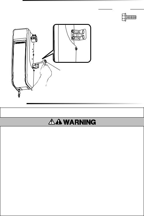
2 Attach the Emergency Release Rope and Handle
1.Insert one end of the emergency release rope through the handle. Make sure that “NOTICE” is right side up. Secure with an overhand knot at least 1" (2.5 cm) from the end of the rope to prevent slipping.
2.Insert the other end of the emergency release rope through the hole in the trolley release arm. Mount the emergency release within reach, but at least 6 feet (1.83 m) above floor, avoiding contact with vehicles to prevent accidental release and secure with an overhand knot.
NOTE: If it is necessary to cut the rope, heat seal the cut end with a match or lighter to prevent unraveling.
Garage Door
Opener
Emergency
Release Cable
Overhand
Knot
Emergency |
Release Handle |
Overhand
Knot
3 Install the Automatic Door Lock
The automatic door lock (model 841LM) is used to prevent the door from being manually opened once the door is fully closed, see Accessories page 37
NOTE: Older model 24 V door locks are incompatible.
1.The lock must be mounted within 10 ft. (3.05 m) of door opener If possible, mount on same side as
door opener. The third roller from the bottom is ideal for most installations.
2.Ensure rail surface is clean and attach the lock template to the track so
that the bolt hole is approximately 3" (7.6 cm) from the center of a door roller.
3.Drill holes as marked on the template.
4.Fasten automatic door lock to the outside of the door track with hardware provided.
5.Run bell wire up wall to door opener. Use insulated staples to secure wire in several places. Insert wire through the bottom of the door opener.
6.Plug the connector into either plug in the door opener.
A secondary door lock can be installed on the opposite side of the door following the instructions above.

 6
6
1
10 feet (3.05 m) max.
4
To prevent possible SERIOUS INJURY or DEATH from a falling garage door:
•If possible, use emergency release handle to disengage door ONLY when garage door is CLOSED. Weak or broken springs or unbalanced door could result in an open door falling rapidly and/or unexpectedly.
•NEVER use emergency release handle unless garage doorway is clear of persons and obstructions.
HARDWARE
Handle
Rope
HARDWARE
Screw 1/4"- 20x1/2" (2)
5 |
Door Track
Lock
Template 
 2
2
3" (7.6 cm)
Roller


 3
3
10
Installation
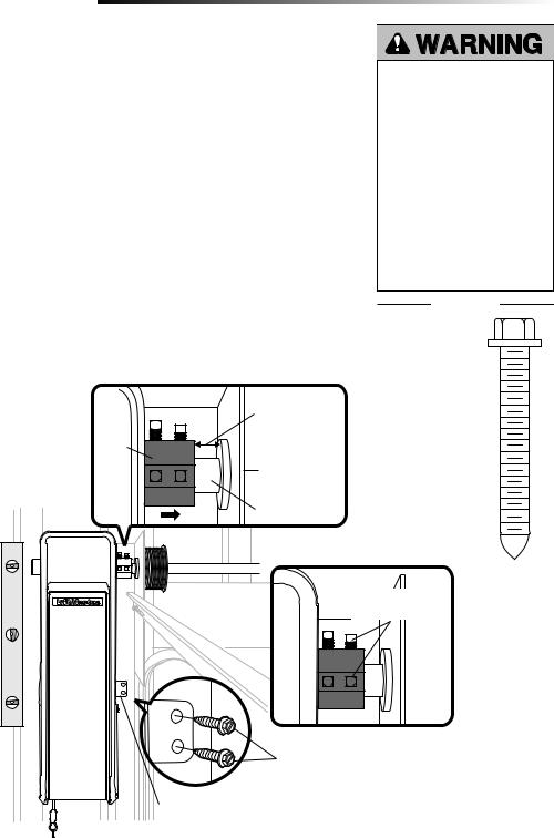
4 Attach the Cable Tension Monitor (Required)
NOTE: The cable tension monitor is shipped for left side installation. It is recommended that the cable tension monitor be installed on the same side of the door as the door opener. For right side installation, remove the snap-ring holding the roller in place and reassemble it on the opposite side of the cable tension monitor.
1.Make sure the door cable is approximately 3/4" (19 mm) from the mounting surface. Door adjustments or shimming may be required to achieve proper depth for the door cable.
2.Position the cable tension monitor so the roller is 2"-6" from the drum and the roller
extends 1/8"-1/4" past the cable. Make sure cable tension monitor is located over a wood support member and the roller is free from any obstructions.
NOTE: There must be no obstructions in the installation area that prevent the cable tension monitor from closing completely when slack is detected.
3. Mark and drill 3/16" pilot holes for screws (pilot holes are not required for anchors). 4. Attach the cable tension monitor to the wall using the hardware provided. Make sure
that the roller is on top of the cable.
5.Run bell wire to door opener. Use insulated staples to secure wire.
6.Connect bell wire to the green quick-connect terminals on the door opener (polarity is not important).
NOTE: Cable must have tension through entire door travel. Make sure there is no slack in cable on opposite side of door during normal operation. If slack occurs during door travel, adjust cables as required.
A second cable tension monitor may be installed for additional security. When two cable tension monitors are installed, the door will not move in the down direction or will reverse if one of the monitors detects slack or is disconnected.
If one of the cable tension monitors is removed, unplug both monitors from the opener. Then plug in the monitor you wish to use and unplug and plug in the opener three times to relearn the monitor to the opener.
To insert or release wire, push in tab with screwdriver tip
(to garage door opener) |
|
Drum |
|
Cable |
|
WHT/ |
|
GRN |
|
|
Cable |
|
Tension |
|
Monitor |
1/8"-1/4" |
Cable Tension |
(3-6 mm) |
Monitor Roller |
The cable tension monitor MUST be connected and properly installed before the garage door opener will move in the down direction.
The cable tension monitor detects ANY slack that may occur in the cables and will reverse the door, eliminating service calls.
HARDWARE
Screw 14-10x2" (2)
Screws #8-32x1" (2)
SIDE VIEW
Drum
Wall
2"-6" (5-15 cm)
 Cable Tension
Monitor Roller
 Approx. 3/4" (19 mm)
 (to cable tension monitor)
11

Installation
5 Install the Door Control (Smart Control Panel®)
Install door control within sight of garage door, out of reach of small children at a minimum height of 5 feet (1.5 m) above floors, landings, steps or any other adjacent walking surface, and away from ALL moving parts of door.
Your garage door opener is compatible with up to 2 Smart Control Panels or 4 of any other Security+ 2.0® door controls. NOTE: Older LiftMaster door controls and third party products are not compatible.
For gang box installations it is not necessary to drill holes or install the drywall anchors. Use the existing holes in the gang box.
1.Strip 7/16" (11 mm) of insulation from one end of the wire and separate the wires.
2.Connect one wire to each of the two screws on the back of the door control. The wires can be connected to either screw. PRE-WIRED INSTALLATIONS: Choose any two wires to connect, but make note of which wires are used.
3.Mark the location of the bottom mounting hole and drill a 5/32" (4 mm) hole.
4.Install the bottom screw, allowing 1/8" (3 mm) to protrude from the wall.
5.Position the bottom hole of the door control over the screw and slide down into place.
6.Lift the push bar up and mark the top hole.
7.Remove the door control from the wall and drill a 5/32" (4 mm) hole for the top screw.
8.Position the bottom hole of the door control over the screw and slide down into place. Attach the top screw.
9.Run the white and red/white wire from the door control to the garage door opener. Attach the wire to the wall and ceiling with the staples (not applicable for gang box or pre-wired installations). Do not pierce the wire with the staple as this may cause a short or an open circuit.
10.Connect the wire to the red and white terminals on the garage door opener. The wires can be connected to either terminal.
11.Fasten the warning placard to the wall next to the door control.
NOTE: DO NOT connect the power and operate the garage door opener at this time. The door will travel to the full open position but will not return to the close position until the safety reversing sensors are connected and properly aligned. See page 14.
To prevent possible SERIOUS INJURY or DEATH from electrocution:
•Be sure power is NOT connected BEFORE installing door control.
•Connect ONLY to 7-28 VOLT low voltage wires.
To prevent possible SERIOUS INJURY or DEATH from a closing garage door:
•Install door control within sight of garage door, out of reach of small children at a minimum height of 5 feet (1.5 m) above floors, landings, steps or any other adjacent walking surface, and away from ALL moving parts of door.
•NEVER permit children to operate or play with door control push buttons or remote control transmitters.
•Activate door ONLY when it can be seen clearly, is properly adjusted, and there are no obstructions to door travel.
•ALWAYS keep garage door in sight until completely closed. NEVER permit anyone to cross path of closing garage door.
HARDWARE
Screw 6ABx1-1/4" (Standard installation) (2)
Drywall
Anchors (2)
Screw 6-32x1" (pre-wired) (2)
Insulated Staples
(Not shown)
(to garage door opener) |
7/16" (11 mm) |
|
(to door control)
Red |
White |
WHT |
|
|
|
|
WHT/RED |
|
To insert or release wire, push in tab with screwdriver tip
12
Installation
IMPORTANT INSTALLATION INSTRUCTIONS
To reduce the risk of SEVERE INJURY or DEATH:
•This portable luminaire has a polarized plug (one blade is wider than the other) as a feature to reduce the risk of electric shock.
•This plug will fit in a polarized outlet ONLY one way. If the plug does not fit fully in the outlet, reverse the plug. If it still does not fit, contact a qualified electrician.
•.DO NOT alter the plug.
•.Light is intended for ceiling or wall mount and indoor applications ONLY.
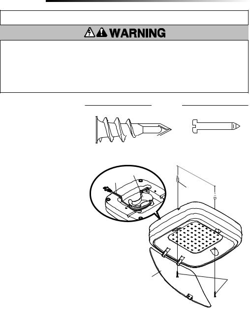
6Install MyQ® Remote LED Light
The MyQ Remote LED Light is designed to plug directly into a standard 120V outlet. Select an appropriate location on the ceiling or wall to mount the light within 6 feet (1.83 m) of an electrical outlet so that the cord and light are away from moving parts.
NOTE: If installing light on drywall and a ceiling joist cannot be located, use drywall anchors provided. No pilot hole is required for drywall anchors.
1.Drill pilot holes 6-1/8" (15.6 cm) apart if mounting to joist.
OR
Screw in drywall anchors 6-1/8" (15.6 cm) apart if mounting to drywall.
2.Determine the length of power cord needed to reach the nearest outlet. Wind any excess cord around cord retainer on the top side of the light base. Route the cord through the channel so the light mounts flush.
3.Open the light lens.
4.Mount the light with the screws provided.
5.Close the light lens.
6.Plug in the light to the outlet.
NOTE: The LED light is very bright. DO NOT stare at the light while on a ladder.
Your garage door opener remote light has already been programmed at the factory to operate with your opener. Any additional or replacement remote lights will need to be programmed.
HARDWARE
Drywall Anchor (screw-in) (2) |
|
|
|
Screw #6x1" (2) |
|||||||||||||||||||||
|
|
|
|
|
|
|
|
|
|
|
|
|
|
|
|
|
|
|
|
|
|
|
|
|
|
|
|
|
|
|
|
|
|
|
|
|
|
|
|
|
|
|
|
|
|
|
|
|
|
|
|
|
|
|
|
|
|
|
|
|
|
|
|
|
|
|
|
|
|
|
|
|
|
|
|
|
|
Cord Retainer |
6-1/8" (15.6 cm) |
|
Channel
Drywall
Anchors 

Light Lens |
Screws |
13
 Loading...