


 Loading...
DF-650
MT-1(A)
BF-1(A)
PH-4A, PH-4C
Operation Guide Einführung Guía de uso
Manuel d'utilisation Guida alle funzioni
Please read this Operation Guide before using this machine. Keep it close to the machine for easy reference.

1 English
Safety Information . . . . . . . . . . . . . . . . . . . . . . . . . . . . . . . . . . . . . . . . . . . . . . . . . . . . . 1-1
Names of Parts . . . . . . . . . . . . . . . . . . . . . . . . . . . . . . . . . . . . . . . . . . . . . . . . . . . . . . . 1-6
Modes . . . . . . . . . . . . . . . . . . . . . . . . . . . . . . . . . . . . . . . . . . . . . . . . . . . . . . . . . . . . . . 1-7
Maintenance. . . . . . . . . . . . . . . . . . . . . . . . . . . . . . . . . . . . . . . . . . . . . . . . . . . . . . . . . 1-16
Troubleshooting . . . . . . . . . . . . . . . . . . . . . . . . . . . . . . . . . . . . . . . . . . . . . . . . . . . . . . 1-19
Specifications . . . . . . . . . . . . . . . . . . . . . . . . . . . . . . . . . . . . . . . . . . . . . . . . . . . . . . . . 1-32
2 Deutsch
Sicherheitshinweise . . . . . . . . . . . . . . . . . . . . . . . . . . . . . . . . . . . . . . . . . . . . . . . . . . . . 2-1
Komponenten. . . . . . . . . . . . . . . . . . . . . . . . . . . . . . . . . . . . . . . . . . . . . . . . . . . . . . . . . 2-6
Betriebsarten . . . . . . . . . . . . . . . . . . . . . . . . . . . . . . . . . . . . . . . . . . . . . . . . . . . . . . . . . 2-7
Wartung . . . . . . . . . . . . . . . . . . . . . . . . . . . . . . . . . . . . . . . . . . . . . . . . . . . . . . . . . . . . 2-16
Störungsbeseitigung. . . . . . . . . . . . . . . . . . . . . . . . . . . . . . . . . . . . . . . . . . . . . . . . . . . 2-19
Technische Daten. . . . . . . . . . . . . . . . . . . . . . . . . . . . . . . . . . . . . . . . . . . . . . . . . . . . . 2-32
3 Español
Información de seguridad. . . . . . . . . . . . . . . . . . . . . . . . . . . . . . . . . . . . . . . . . . . . . . . . 3-1 Nombres de los componentes . . . . . . . . . . . . . . . . . . . . . . . . . . . . . . . . . . . . . . . . . . . . 3-6 Modos . . . . . . . . . . . . . . . . . . . . . . . . . . . . . . . . . . . . . . . . . . . . . . . . . . . . . . . . . . . . . . 3-7 Mantenimiento . . . . . . . . . . . . . . . . . . . . . . . . . . . . . . . . . . . . . . . . . . . . . . . . . . . . . . . 3-16 Solución de problemas. . . . . . . . . . . . . . . . . . . . . . . . . . . . . . . . . . . . . . . . . . . . . . . . . 3-19 Especificaciones . . . . . . . . . . . . . . . . . . . . . . . . . . . . . . . . . . . . . . . . . . . . . . . . . . . . . 3-32
4 Français
Informations de sécurité. . . . . . . . . . . . . . . . . . . . . . . . . . . . . . . . . . . . . . . . . . . . . . . . . 4-1
Nomenclature. . . . . . . . . . . . . . . . . . . . . . . . . . . . . . . . . . . . . . . . . . . . . . . . . . . . . . . . . 4-6
Modes . . . . . . . . . . . . . . . . . . . . . . . . . . . . . . . . . . . . . . . . . . . . . . . . . . . . . . . . . . . . . . 4-7
Entretien. . . . . . . . . . . . . . . . . . . . . . . . . . . . . . . . . . . . . . . . . . . . . . . . . . . . . . . . . . . . 4-16
Dépannage. . . . . . . . . . . . . . . . . . . . . . . . . . . . . . . . . . . . . . . . . . . . . . . . . . . . . . . . . . 4-19
Spécifications . . . . . . . . . . . . . . . . . . . . . . . . . . . . . . . . . . . . . . . . . . . . . . . . . . . . . . . . 4-32
5 Italiano
Informazioni sulla sicurezza . . . . . . . . . . . . . . . . . . . . . . . . . . . . . . . . . . . . . . . . . . . . . . 5-1 Componenti . . . . . . . . . . . . . . . . . . . . . . . . . . . . . . . . . . . . . . . . . . . . . . . . . . . . . . . . . . 5-6 Modalità . . . . . . . . . . . . . . . . . . . . . . . . . . . . . . . . . . . . . . . . . . . . . . . . . . . . . . . . . . . . . 5-7 Manutenzione. . . . . . . . . . . . . . . . . . . . . . . . . . . . . . . . . . . . . . . . . . . . . . . . . . . . . . . . 5-16 Risoluzione dei problemi . . . . . . . . . . . . . . . . . . . . . . . . . . . . . . . . . . . . . . . . . . . . . . . 5-19 Specifiche. . . . . . . . . . . . . . . . . . . . . . . . . . . . . . . . . . . . . . . . . . . . . . . . . . . . . . . . . . . 5-32
DF-650, MT-1(A), BF-1(A), PH-4A AND PH-4C OPERATION GUIDE |
i |

ii |
DF-650, MT-1(A), BF-1(A), PH-4A AND PH-4C OPERATION GUIDE |
1 English
Safety Information
ALWAYS read this Operation Guide thoroughly before use. After reading, keep it together with the Operation Guide for your copier.
Refer to the Operation Guide for your copier for information on the service representative for your product.
The sections of this Operation Guide and parts of this product marked with symbols are safety warnings. These are designed to protect the user, other individuals and surrounding objects, and ensure correct and safe usage of the product.
DANGER: Indicates that serious injury or even death will very possibly result from insufficient attention to or incorrect compliance with the related points.
WARNING: Indicates that serious injury or even death may result from insufficient attention to or incorrect compliance with the related points.
CAUTION: Indicates that personal injury or mechanical damage may result from insufficient attention to or incorrect compliance with the related points.
Symbols
The  symbol indicates that the related section includes safety warnings. Specific points of attention are indicated inside the symbol.
[General warning]
....
The  symbol indicates that the related section includes information on prohibited actions. Specifics of the prohibited action are indicated inside the symbol.
[Warning of prohibited action]
....
[Disassembly prohibited]
....
DF-650, MT-1(A), BF-1(A), PH-4A AND PH-4C OPERATION GUIDE |
1-1 |

English
The zsymbol indicates that the related section includes information on actions which must be performed. Specifics of the required action are indicated inside the symbol.
[Alert of required action]
....
[Remove the power plug from the outlet]
....
[Always connect the machine to an outlet with a ground
.... connection]
Please contact your service representative to order a replacement if the safety warnings in this Operation Guide are illegible or if the guide itself is missing (fee required).
1-2 |
DF-650, MT-1(A), BF-1(A), PH-4A AND PH-4C OPERATION GUIDE |
English
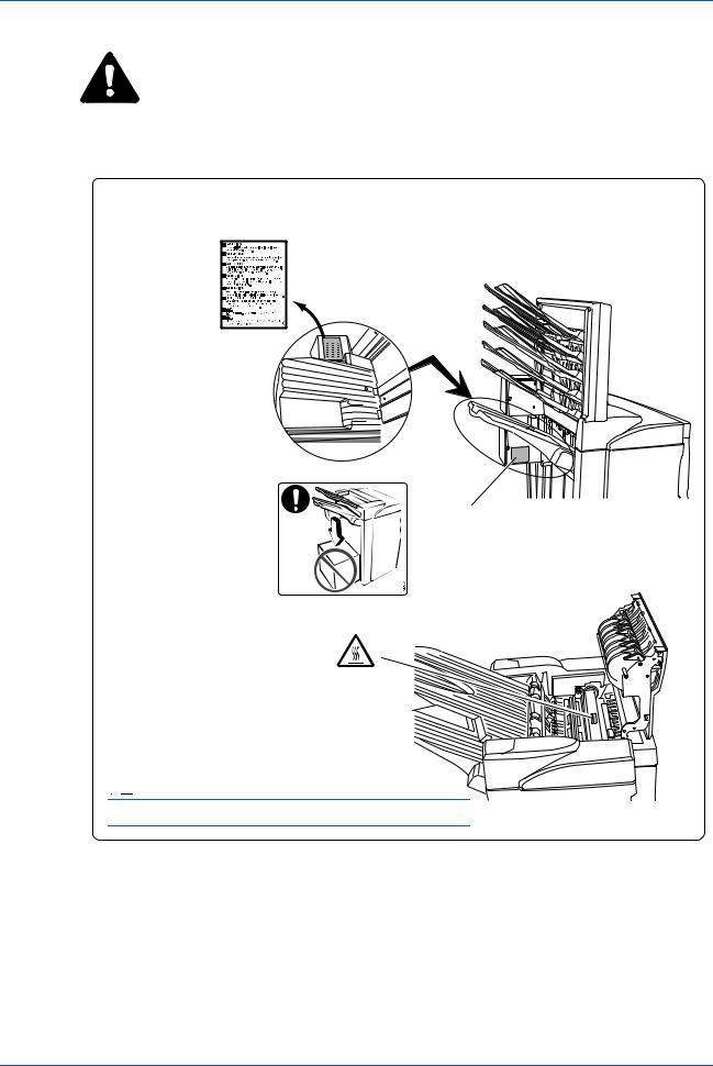
CAUTION LABELS
Caution labels have been attached to the Document Finisher at the following locations for safety purposes. BE VERY CAREFUL to avoid getting your fingers caught in or burned by the machine when clearing a paper jam.
LABEL 1
WARNING: To avoid injury to your hands, wait until the copier stops before removing paper.
LABEL 2
2
DO NOT place any objects underneath Tray A.
LABEL 3
The interior of this section reaches high temperatures. DO NOT touch this 
 section as there is a danger of
 being
being

 burned.
NOTE: DO NOT REMOVE THESE LABELS.
DF-650, MT-1(A), BF-1(A), PH-4A AND PH-4C OPERATION GUIDE |
1-3 |

English
 INSTALLATION PRECAUTIONS
Environment
CAUTION: Avoid placing this product on or in locations which are unstable or not level. Such locations may cause the product to fall down or fall over. This type of situation presents a danger of personal injury or damage to the product.
CAUTION: Avoid locations near radiators, heaters, or other heat sources, or locations near flammable items, to avoid the danger of fire.
Other precautions
Depending upon the location in which this product is installed, adverse environmental conditions may affect its performance. Ensure this product is installed in an air-conditioned room (recommended room temperature: around 68°F (20°C), humidity: around 65%) and avoid the following locations when selecting a site for installation:
•bright locations near a window or with exposure to direct sunlight
•locations with vibrations
•locations with drastic fluctuations in temperature or humidity
•locations with direct exposure to hot or cold air
Handling of plastic bags
WARNING: Keep the plastic bags that are used with this product away from children. The plastic may cling to their nose and mouth causing suffocation.
PRECAUTIONS FOR USE
Cautions when using this product
WARNING: DO NOT place metallic objects or containers with water (flower vases, flower pots, cups, etc.) on or near this product. This type of situation presents a danger of fire or electrical shock should any water fall inside.
WARNING: DO NOT damage, break or attempt to repair the signal line. DO NOT place heavy objects on the signal line, pull it, bend it unnecessarily or cause any other type of damage. These types of situations present a danger of fire or electrical shock.
WARNING: NEVER attempt to repair or disassemble this product or its parts as there is a danger of injury or fire.
WARNING: If this product becomes excessively hot, smoke appears, there is an odd smell, or any other abnormal situation occurs, there is a danger of fire or electrical shock. Immediately turn OFF (O) the copier’s main power switch, remove the copier's power plug from its outlet and contact your service representative.
1-4 |
DF-650, MT-1(A), BF-1(A), PH-4A AND PH-4C OPERATION GUIDE |

English
WARNING: If anything harmful (paper clips, water, other fluids, etc.) falls into this product, turn OFF (O) the copier’s main power switch immediately, remove the copier's power plug from its outlet and contact your service representative. If you continue to use this product without taking these steps, there is a danger of fire or electrical shock.
WARNING: ALWAYS contact your service representative for maintenance or repair of internal parts.
CAUTIONS
CAUTION: For safety purposes, ALWAYS turn OFF (O) the copier’s main power switch and remove the copier's power plug from its outlet when performing cleaning operations on this product.
CAUTION: DO NOT touch the ejection tray when the product is in operation as there is a danger of injury.
CAUTION: If dust accumulates within this product, there is a danger of fire or other problems. It is therefore recommended that you consult with your service representative in regard to cleaning of internal parts. This is particularly effective if performed prior to seasons of high humidity. Consult with your service representative in regard to the cost of cleaning the internal parts of the product.
Other Precautions
DO NOT place heavy objects on this product or cause other damage to the product.
When lifting or moving the product, contact your service representative.
Do not touch electrical parts, such as connectors or printed circuit boards. They could be damaged by static electricity.
DO NOT attempt to perform any operations not explained in this Operation Guide.
DF-650, MT-1(A), BF-1(A), PH-4A AND PH-4C OPERATION GUIDE |
1-5 |

English
Names of Parts
|
|
16 |
9 |
10 |
11 |
|
|
|
|
|
|
|
|
15 |
|
|
|
12 |
13 |
14 |
|
|
|
|
|
|
|
|
|
|
|
1 |
2 |
|
|
|
|
|
|
5 |
|
|
|
3 |
|
|
|
|
4 |
|
|
|
|
|
|
|
|
|
17 |
|
|
|
|
|
8 |
7 |
|
|
|
|
|
6 |
|
|
|
|
19 |
|
|
|
20 |
|
|
|
|
|
|
|
|
|
|
|
|
|
18 |
24 |
|
|
|
|
|
|
|
|
22 |
|
|
|
|
|
|
|
21 |
|
|
|
23 |
|
|
Document Finisher (main body)
1Tray A
2Tray B
3Front cover
4Front cover handle
5Upper cover
6Internal tray
7Internal tray handle (G3)
8Internal tray release lever (G4)
9Pressure roller adjuster (G5)
10Conveyor knob (G1)
11Coupling section's lower guide lever (G2)
12Staple cartridge holder A
13Staple cartridge holder B
14Coupling section's upper guide lever
Hole Punch Unit (option)
15Hole Punch Unit (main body)
16Hole Punch Unit adjustment dial
17Waste Hole Punch box
Center-Folding Unit (option)
18Unit release lever (G6)
19Unit release handle (G7)
20Center-Folding Unit lock release lever
21Center-Folding Unit installation buttons
22Conveyor guide lever
23Storage cover
Multi-Job Tray Unit (option)
24 Job Trays 1 - 5
1-6 |
DF-650, MT-1(A), BF-1(A), PH-4A AND PH-4C OPERATION GUIDE |
English
Modes
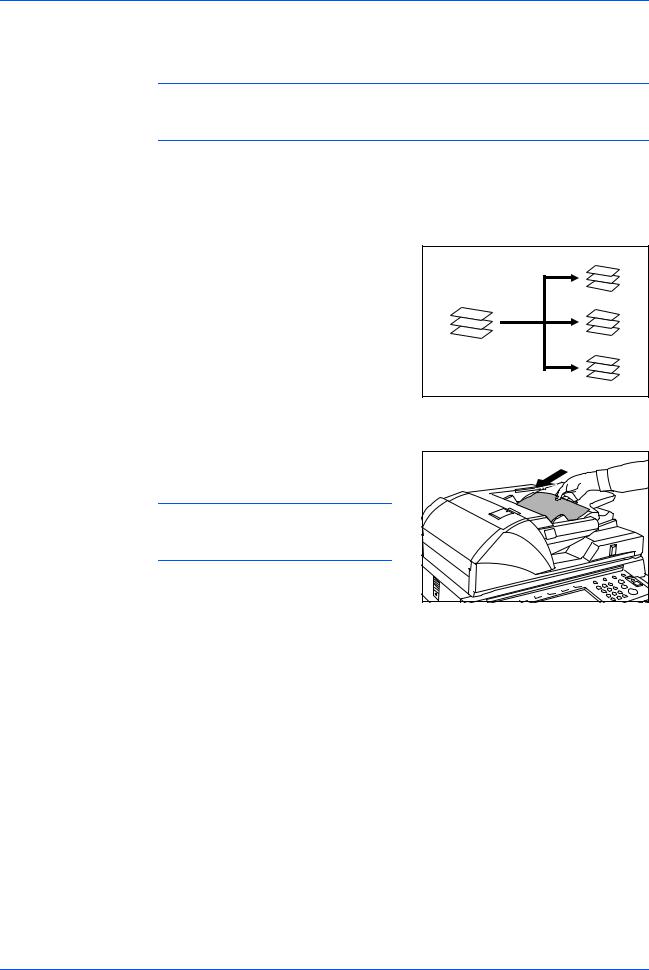
Sort: ON Mode
Sorts copies of multiple originals into |
|
identical sets. For example A,B,C,D |
|
A,B,C,D A,B,C,D. |
|
The following paper sizes can be used in |
A |
Sort:ON Mode: |
B |
C |
|
|
D |
•A3, B4, A4, A4R, B5,11 x 17",
8 1/2 x 14" (Legal), 8 1/2 x 11" (Letter) and 11 x 8 1/2".
1 |
Select Sort: On Mode on the operation panel of your copier. |
2 |
Load the originals in the Document |
|
Processor, or one at a time on the Platen. |
|
NOTE: Refer to the Operation Guide |
|
for your copier for Document Processor |
|
and Platen specifications. |
3 |
Select other features as required and press Start. |
4 |
Copies are ejected onto the specified tray. |
|
If Tray A is selected, each copy set can be |
|
offset from the previous set. Refer to the |
|
Operation Guide for your copier for further |
|
details. |
A B C D
A B C D
A B C D
DF-650, MT-1(A), BF-1(A), PH-4A AND PH-4C OPERATION GUIDE |
1-7 |
English
If Tray A and Tray B both reach their maximum capacity, a message displays. Remove all copies from both trays to continue.
NOTE: The maximum number of copies that can be stored on Tray A and Tray B differs depending on the size of copy paper being used. For further information refer to Tray Capacity on page 1-32.
5 On completion of the job, remove the copies.
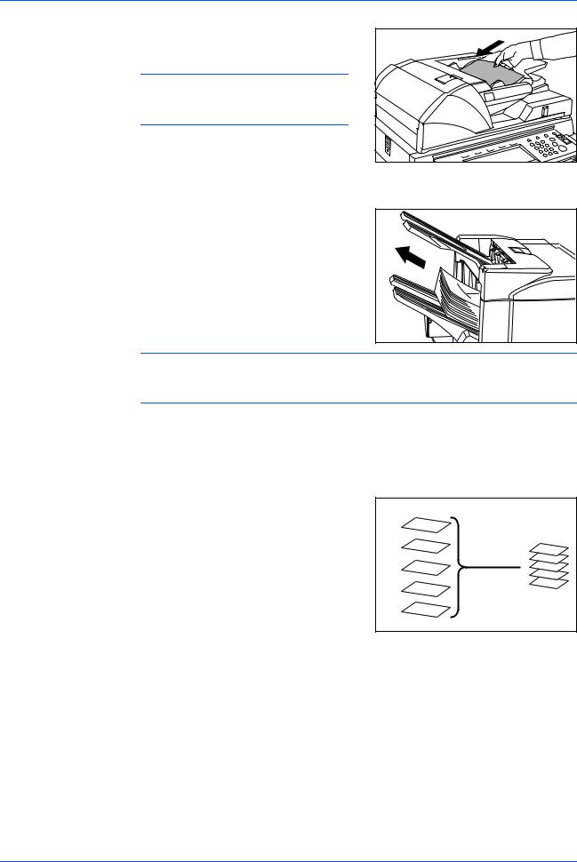
Sort: OFF Mode
Groups the copies of each individual original together in one stack. For example A,A,A B,B,B C,C,C.
The following paper sizes can be used in
Sort:OFF Mode:
•A3, B4, A4, A4R, B5,11 x 17",
8 1/2 x 14" (Legal), 8 1/2 x 11" (Letter) and 11 x 8 1/2".
|
A |
|
A |
|
A |
A |
B |
B |
B |
C |
B |
|
C |
|
C |
|
C |
1 |
Select Sort: Off Mode on the operation panel of your copier. |
2 |
Load the originals in the Document |
|
Processor, or one at a time on the Platen. |
|
NOTE: Refer to the Operation Guide |
|
for your copier for Document Processor |
|
and Platen specifications. |
3 Select other features as required and press Start.
1-8 |
DF-650, MT-1(A), BF-1(A), PH-4A AND PH-4C OPERATION GUIDE |

|
English |
4 |
Copies are ejected onto the specified tray. |
|
If Tray A is selected, each stack can be |
|
offset from the previous stack. Refer to the |
|
Operation Guide for your copier for further |
|
details. |
|
If Tray A and Tray B both reach their |
|
maximum capacity, a message displays. |
|
Remove all copies from both trays to |
|
continue. |
NOTE: The maximum number of copies that can be stored on Tray A and Tray B differs depending on the size of copy paper being used. For further information refer to Tray Capacity on page 1-32. If the number of copies to be made at one time in Non-Sort Mode exceeds the maximum capacity for Tray B (200 sheets), all copies thereafter are ejected onto Tray A.
5 On completion of the job, remove the copies.
Staple Mode
Sorts and staples each copy set.
Stapling options are as follows:
•Upper Left Single Staple
•Upper Right Single Staple
•Double Staple
|
A |
|
|
B |
|
|
C |
|
|
D |
|
A |
A |
|
B |
B |
|
C |
C |
|
D |
||
D |
||
|
||
|
A |
|
|
B |
|
|
C |
|
|
D |
1
2
NOTE: For stapling specifications, refer to Staple Unit on page 1-32.
Select Sort: On Mode on the operation panel of your copier.
Select the staple setting required.
A |
|
A |
|
A |
|
A |
|
|||
|
|
|
|
|
|
|
|
|
|
|
|
|
|
|
|
|
|
|
|
|
|
|
|
|
|
|
|
|
|
|
|
|
|
|
|
|
|
|
|
|
|
|
|
|
|
|
|
|
|
|
|
|
|
|
|
|
|
|
|
|
|
|
|
|
|
|
|
|
|
|
|
|
|
|
|
|
|
|
|
|
|
|
|
|
|
|
|
A |
|
|
|
A |
|
|
|
A |
|
|
|
A |
|
|
||||
|
|
|
|
|
|
|
||||||||||||
|
|
|
|
|
|
|
|
|
|
|
|
|
|
|
|
|
|
|
|
|
|
|
|
|
|
|
|
|
|
|
|
|
|
|
|
|
|
|
|
|
|
|
|
|
|
|
|
|
|
|
|
|
|
|
|
|
|
|
|
|
|
|
|
|
|
|
|
|
|
|
|
|
|
|
|
|
|
|
|
|
|
|
|
|
|
|
|
|
|
|
|
|
|
|
|
|
|
|
|
|
|
|
|
|
|
|
|
|
|
|
|
|
|
|
|
|
|
|
|
|
|
|
|
|
|
|
|
|
|
|
|
|
|
|
|
|
|
|
|
|
|
|
|
|
|
|
|
|
|
|
|
|
|
|
|
|
|
|
|
|
|
|
|
|
|
|
|
|
|
|
A |
|
|
|
A |
|
|
|
A |
|
|
|||
|
|
|
|
||||||||||
|
|
|
|
|
|
|
|
|
|
|
|
|
|
|
|
|
|
|
|
|
|
|
|
|
|
|
|
|
|
|
|
|
|
|
|
|
|
|
|
|
|
|
|
|
|
|
|
|
|
|
|
|
|
|
|
|
|
|
|
|
|
|
|
|
|
|
|
|
|
|
|
|
|
|
|
|
|
|
|
|
|
|
|
|
|
|
|
|
|
|
|
|
|
|
|
|
|
|
|
|
|
|
|
|
|
|
|
|
|
|
|
|
|
|
|
|
|
|
|
|
|
|
|
|
|
A |
|
|
|
A |
|
|
|
A |
|
|
|||
|
|
|
|
|
|
|
|||||||
|
|
|
|
|
|
|
|
|
|
|
|
|
|
|
|
|
|
|
|
|
|
|
|
|
|
|
|
|
|
|
|
|
|
|
|
|
|
|
|
|
|
|
|
|
|
|
|
|
|
|
|
|
|
|
|
|
|
|
|
|
|
|
|
|
|
|
|
|
|
|
|
|
|
|
|
|
|
|
|
|
|
|
|
|
|
|
|
|
|
|
|
|
|
|
|
|
|
|
|
|
|
|
|
|
|
|
|
|
|
|
|
|
|
|
|
|
|
|
|
|
|
|
|
|
|
DF-650, MT-1(A), BF-1(A), PH-4A AND PH-4C OPERATION GUIDE |
1-9 |
English
3 |
Load the originals in the Document |
|
Processor, or one at a time on the Platen. |
4
5
6
NOTE: Refer to the Operation Guide for your copier for Document Processor and Platen specifications.
Select other features as required and press Start.
Copies will be stapled and ejected onto Tray
A, face down.
If Tray A reaches its maximum capacity, a message displays. Remove all copies from Tray A to continue.
NOTE: The maximum number of copies that can be stored  on Tray A differs depending on the size of copy paper being used. For further information refer to
Tray Capacity on page 1-32.
On completion of the job, remove the copies.
Non-Sort Mode
Use this mode when sorting or grouping are not required.
ALWAYS use Non-Sort Mode when copying onto transparencies or other special material or paper.
A
B A B
C  C D
C D
E
D
E
1-10 |
DF-650, MT-1(A), BF-1(A), PH-4A AND PH-4C OPERATION GUIDE |

English
Booklet Stitching Mode
|
In this mode, copies are stapled in two |
|
|
positions in the center of the paper. |
|
|
The following paper sizes can be used in |
|
|
Booklet Stitching mode: |
|
|
• |
A3, B4, A4R, 11 x 17", 8 1/2 x 14" |
|
|
(Legal) and 11 x 8 1/2". |
|
Stapling Capacity: 2 to 16 sheets at a time. |
|
|
The optional Center-Folding Unit is required |
|
|
for automatic folding. |
|
|
The Booklet Copy function on your copier |
|
|
can be used to automatically produce |
|
|
booklets ready for stitching and folding. |
|
|
Refer to the Operation Guide for your copier |
|
|
for more information. |
|
1 |
Select the Booklet Stitching mode on the operation panel of your copier. |
|
|
Refer to the Operation Guide for your copier for more detailed information. |
|
2 |
Load the originals in the Document |
|
|
Processor, or one at a time on the Platen. |
|
|
NOTE: Refer to the Operation Guide |
|
|
for your copier for Document Processor |
|
|
and Platen specifications. |
|
|
The maximum number of sheets that can be |
|
|
stitched at one time is 16. Up to 64 originals |
|
|
can be used in this mode. |
|
3 |
Select other features as required and press |
|
|
Start. |
|
|
If using the Platen, a message displays after |
|
|
each original is scanned to determine |
|
|
whether another original requires scanning |
|
|
or if copying can commence. |
|
NOTE: Refer to the Operation Guide for your copier for further details.
DF-650, MT-1(A), BF-1(A), PH-4A AND PH-4C OPERATION GUIDE |
1-11 |
English
4 |
Copies will be automatically stapled and |
|
ejected onto the storage cover. |
If the maximum capacity is reached, a message displays. Remove all copies from the storage cover to continue.
|
NOTE: For further information refer to Center-Folding Unit (option) on page 1-33. |
5 |
On completion of the job, remove the copies |
|
from the storage cover. |
Hole Punch Mode
The Hole Punch Unit is an optional device. This mode produces hole punched copies automatically.
The following paper sizes can be used:
• 2-hole punch: A3, B4, A4, A4R, B5, B5R, A5R, Folio, 8 1/2 x 14" (Legal), 8 1/2 x 11" (Letter) and 5 1/2 x 8 1/2"
•3-hole punch: 11 x 17" and 11 x 8 1/2"
•4-hole punch: A3 and A4
Hole Punch mode can be used with Sort: ON, Staple and Sort: OFF modes. Paper weights must be between 45 g/m2 and 200 g/m2.
NOTE: B5R can only be selected if copies are ejected onto Tray A. In Sort: ON mode and Staple mode, B5R and Folio cannot be selected.
1 Select Hole Punch mode on the operation panel of your copier.
NOTE: Refer to the Operation Guide for your copier for more detailed information.
1-12 |
DF-650, MT-1(A), BF-1(A), PH-4A AND PH-4C OPERATION GUIDE |
|
English |
2 |
Load the originals in the Document |
|
Processor, or one at a time on the Platen. |
|
Ensure the orientation of the originals is the |
|
same as that selected for Hole Punch mode |
|
on the copier. |
NOTE: Refer to the Operation Guide for your copier for Document Processor and Platen specifications.
3 |
Select other features as required and press Start. |
4 |
The copies are automatically hole punched |
|
and ejected onto Tray B. |
NOTE: Holes are punched in each copy individually, therefore the location of the holes may vary on each sheet.
On completion of the job, remove all the copies.
NOTE: If the maximum capacity for Tray B is exceeded, all subsequent copies will be ejected onto Tray A. If Tray A is not engaged when Tray B becomes full, an error message displays. Remove all copies to continue.
Interrupt Mode
When using Interrupt Mode, the copies for the interrupt job are usually ejected onto the finisher tray not currently in use. If required, a different tray can be selected on the copier Operation Panel.
NOTE: Refer to the Operation Guide for your copier for further details.
DF-650, MT-1(A), BF-1(A), PH-4A AND PH-4C OPERATION GUIDE |
1-13 |
English
Multi-Job Tray Mode
The Multi-Job Tray Unit is an optional device. Print or Copy output can be ejected into a specified Multi-Job Tray.
This option is extremely useful when more than one user is using the copier as a printer. The printed documents for each user will be ejected into the job tray selected.
The following paper sizes can be used:
•Plain paper (80 g/m2): between A3 and B6R, or Folio, 11 x 17" and 8 1/2 x 11"
•Recycled paper (80 g/m2): A3, A4, A4R, 11 x 17", 11 x 8 1/2" and 8 1/2 x 11"
•Colored paper (80 g/m2): A4, A4R, 8 1/2 x 11" and 11 x 8 1/2"
|
NOTE: The maximum number of copies that can be stored in each job tray will |
|||
|
differ depending on the size of copy paper being used. For further information refer |
|||
|
to Multi-Job Tray Unit (option) on page 1-33. |
|||
1 |
|
|
|
|
Write the name of the user of each job tray |
|
|
||
|
|
|
||
|
|
|
||
|
on the labels provided. |
|
|
|
|
|
|
|
|
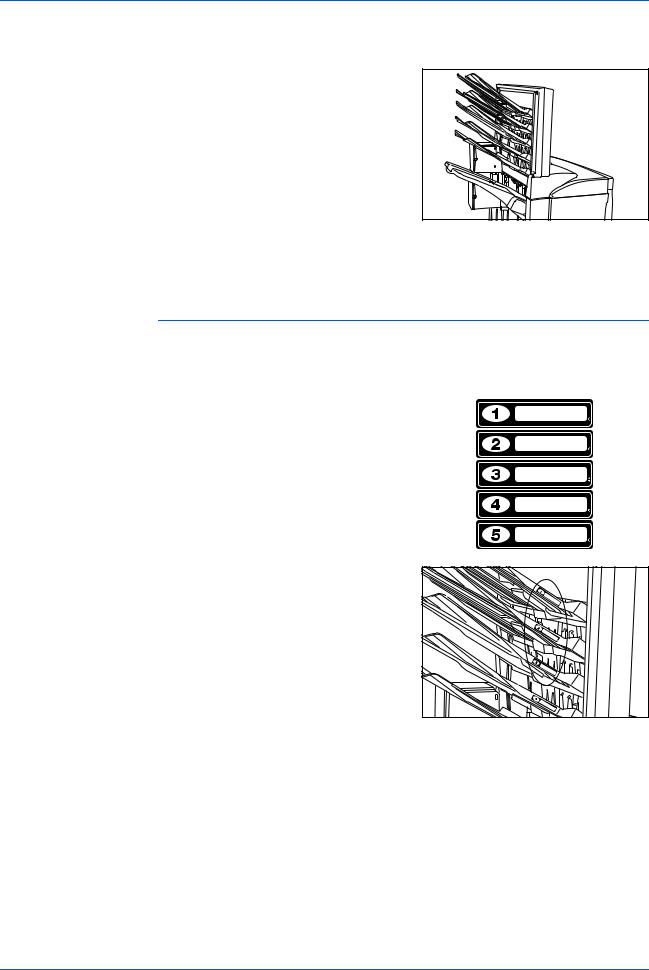
2 |
Attach the labels to the job trays, in the |
|
location indicated on the illustration. |
The trays to which labels should be applied are 1, 2, 3, 4, and 5, as counted from the top down.
3
4
Use the application in your computer to select a job tray between 1 and 5.
Select the paper size, page(s) to be printed and number of prints required.
1-14 |
DF-650, MT-1(A), BF-1(A), PH-4A AND PH-4C OPERATION GUIDE |

English
5 Print the job.
Prints will be ejected onto the selected job tray.
6 On completion of the job, remove all prints from the job tray.
NOTE: To use the copier to select the tray required, refer to the Operation Guide for your copier.
DF-650, MT-1(A), BF-1(A), PH-4A AND PH-4C OPERATION GUIDE |
1-15 |
English
Maintenance
Replacing Staples
|
The Document Finisher is equipped with two staple cartridge holders, A and B. The |
|
procedure for replenishing staples is the same for both holders. |
|
If a message displays indicating that staples have run out, the staple cartridge |
|
holder(s) need to be replenished with staples. |
|
NOTE: If the Staple Unit runs out of staples, contact your service representative or |
|
the place of purchase. |
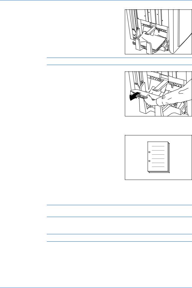
1 |
Grasp the front cover handle and open the |
|
front cover. |
2 |
Grasp the internal tray handle (G3) and pull |
|
the internal tray out. |
3 |
Lift up the staple cartridge holder and pull it |
|
out. |
4 |
Remove the empty staple cartridge from the |
|
staple cartridge holder. |
1-16 |
DF-650, MT-1(A), BF-1(A), PH-4A AND PH-4C OPERATION GUIDE |
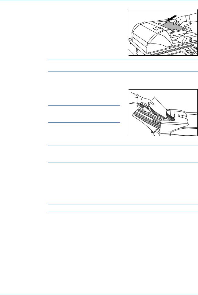
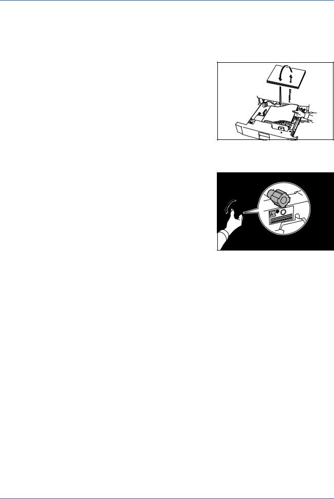
5 |
Remove the new staple cartridge from its |
|
box. |
6 |
Holding the staple cartridge holder in one |
|
hand and the new staple cartridge in the |
|
other, insert the staple cartridge into the |
|
holder. |
|
Ensure the direction of insertion is correct. |
|
Both arrows should point in the same |
|
direction. |
7 |
Ensure the new staple cartridge is inserted |
|
completely into the staple cartridge holder, |
then peel off the paper tape.
8 Re-install the staple cartridge holder.
The staple cartridge holder will click into place when it has been inserted correctly.
9 |
Push the internal tray back into position and |
|
close the front cover. |
English
DF-650, MT-1(A), BF-1(A), PH-4A AND PH-4C OPERATION GUIDE |
1-17 |
English
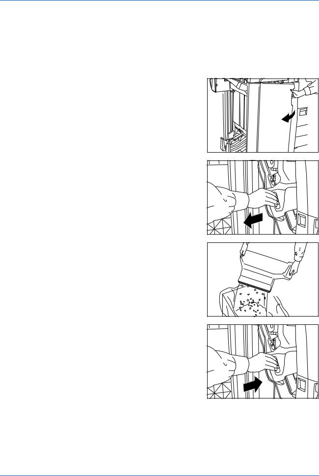
Emptying the Waste Hole Punch Box
|
If the message "Empty waste punch box" displays, the scraps in the waste hole |
|
punch box require emptying. |
|
Leave the main power switch on your copier switched ON ( | ) while performing this |
|
procedure. |
1 |
Grasp the front cover handle and open the |
|
front cover. |
2 |
Grasp the waste hole punch box handle and |
|
remove the box from the Document |
Finisher.
3 |
Dispose of the hole punch scraps |
|
appropriately. |
4 |
Re-install the waste hole punch box. Align it |
|
with the guides in the Document Finisher. |
5 Close the front cover.
1-18 |
DF-650, MT-1(A), BF-1(A), PH-4A AND PH-4C OPERATION GUIDE |
Troubleshooting
General
If ejected copies are not flat or are stacked unevenly, turn over the paper in the cassette and reload it.
If copies are curled, refer to Curled Output on page 1-29.
If a paper jam occurs, check the side guide located in the cassette is adjusted to the size of paper loaded.
Clearing Paper Jams
Leave the main power switched ON ( | ) while performing the procedure to clear paper jams.
Open the cover of the copier and turn the fixer knob (A1) to the left at least 20 times before carrying out the paper jam removal procedure.
Once the jam is cleared, the operation panel on your copier will return to the status and settings prior to the jam.
English
DF-650, MT-1(A), BF-1(A), PH-4A AND PH-4C OPERATION GUIDE |
1-19 |
English
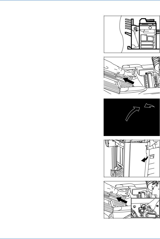
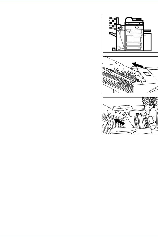
Paper Jam in the Coupling Section
If the illustration shown displays on the operation panel of your copier, there is a paper jam in the coupling section between the Document Finisher and your copier.
1 |
Open the upper cover and remove the |
|
jammed paper. |
If the jammed paper cannot be easily removed, proceed to the next step.
If the optional Hole Punch Unit is installed, ensure the arrow on the adjustment dial points somewhere between the grooves on the main body of the Hole Punch Unit.
2 |
Grasp the front cover handle and open the |
|
front cover. |
3 Turn the conveyor knob (G1) to feed the paper further along to enable easy removal.
Remove the paper.
If the jammed paper cannot be easily removed, proceed to the next step.
1-20 |
DF-650, MT-1(A), BF-1(A), PH-4A AND PH-4C OPERATION GUIDE |
|
English |
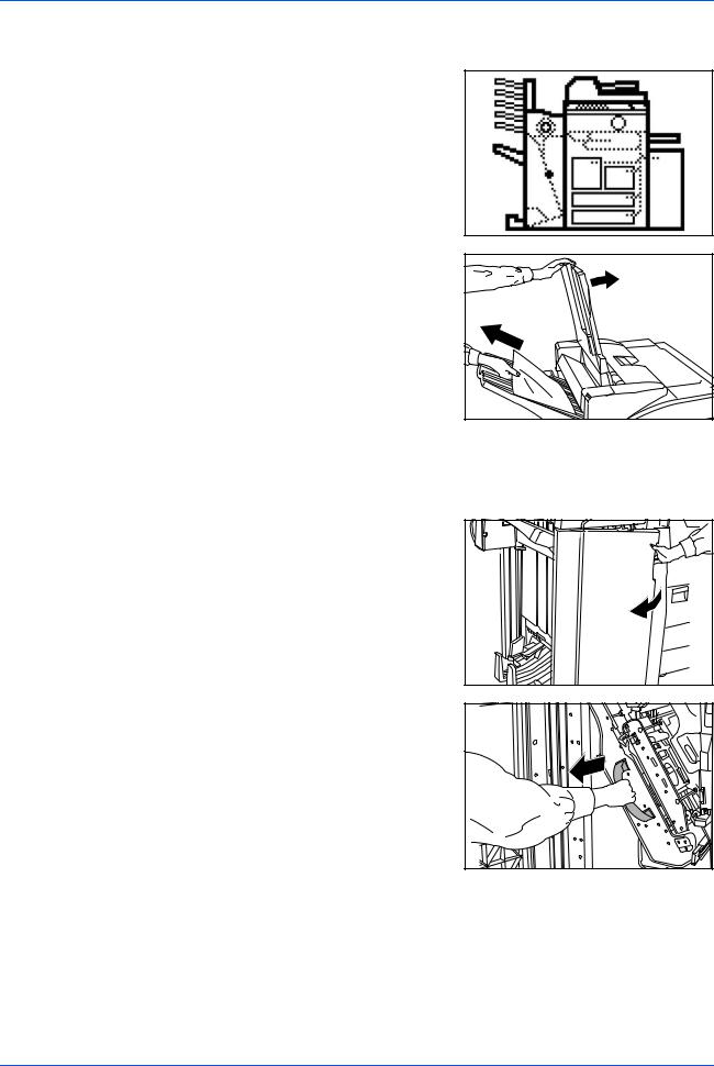
4 |
Lift the coupling section's upper guide lever |
|
and remove the jammed paper. |
|
Close the upper guide lever and the upper |
|
cover. |
5 |
Hold the coupling section's lower guide |
|
lever (G2) and open. |
Close the lower guide.
6 Close the front cover.
Paper Jam in Tray A
If the illustration shown displays on the operation panel of your copier, there is a paper jam in the conveyor section to Tray A.
1 Lift open Tray B.
2 |
If the jammed paper is visible in the eject slot, pull it out in the direction of ejection |
|
without tearing it. |
DF-650, MT-1(A), BF-1(A), PH-4A AND PH-4C OPERATION GUIDE |
1-21 |
English
Paper Jam in Tray B
If the illustration shown displays on the operation panel of your copier, there is a paper jam in the conveyor section to Tray B.
1 If the jammed paper is visible in the eject slot, pull it out in the direction of ejection, without tearing it.
If the jammed paper cannot be easily removed, proceed to the next step.
2 |
Open the upper cover and remove the |
|
jammed paper. |
3 Close the upper cover.
1-22 |
DF-650, MT-1(A), BF-1(A), PH-4A AND PH-4C OPERATION GUIDE |
English
Paper Jam in the Conveyor Section
If the illustration shown displays on the operation panel of your copier, there is a paper jam in the conveyor section to the internal tray.
1
2
Lift open Tray B.
If the jammed paper is visible in the eject slot, pull it out in the direction of ejection, without tearing it.
If the jammed paper cannot be easily removed, proceed to the next step.
3 |
Grasp the front cover handle and open the |
|
front cover. |
4 |
Grasp the internal tray handle (G3) and |
|
carefully pull out the internal tray. |
DF-650, MT-1(A), BF-1(A), PH-4A AND PH-4C OPERATION GUIDE |
1-23 |
English
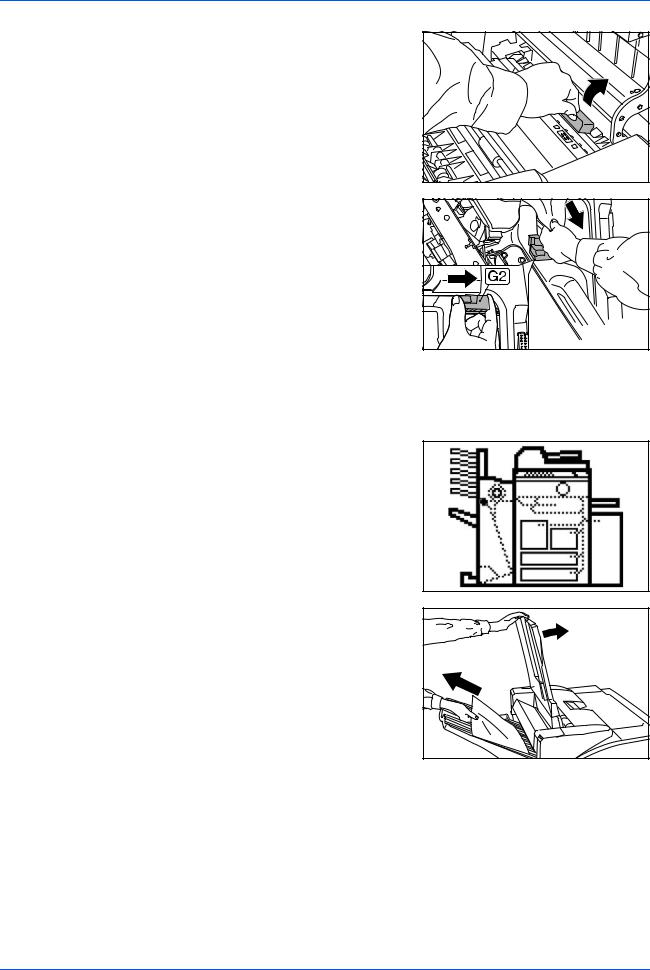
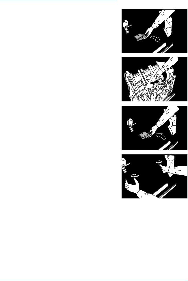
5 |
Hold the internal tray release lever (G4) and |
|
open the internal tray. |
6 Remove the jammed paper.
7 |
Hold the internal tray release lever (G4) and |
|
close the internal tray. |
8 |
Push down on the frame to lock the internal |
|
tray in place. |
9 Push the internal tray back into the Document Finisher and close the front cover.
1-24 |
DF-650, MT-1(A), BF-1(A), PH-4A AND PH-4C OPERATION GUIDE |
Paper Jam in the Multi-Job Tray Unit
If a paper jam occurs in the Multi-Job Tray Unit, follow the procedure below to remove the jammed paper.
1 |
If there is any jammed paper in any of the |
|
job trays, remove it without tearing it. |
2 |
If the jammed paper cannot be easily |
|
removed, open the upper cover to the |
Document Finisher and remove the jammed paper.
For further information refer to Paper Jam in the Coupling Section on page 1-20.
English
DF-650, MT-1(A), BF-1(A), PH-4A AND PH-4C OPERATION GUIDE |
1-25 |
English
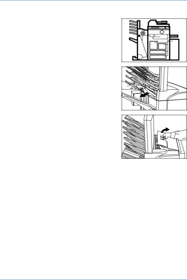
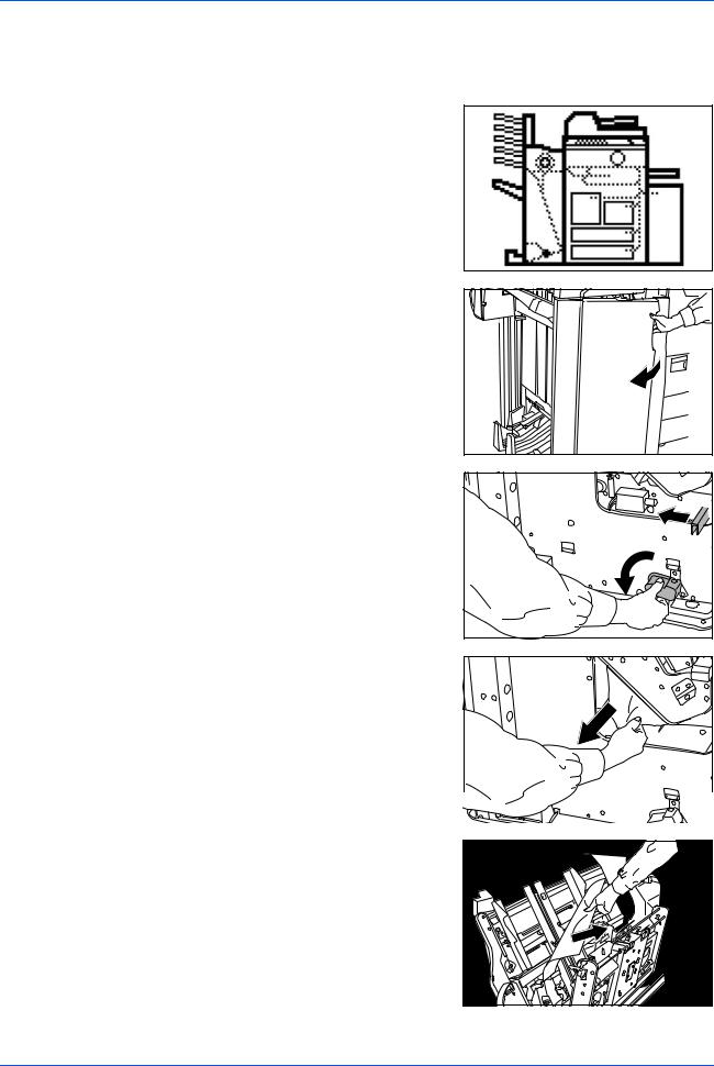
Paper Jam in the Center-Folding Unit
Conveyor Section
If the illustration shown displays on the operation panel of your copier, there is a paper jam in the conveyor section of the
Center-Folding Unit.
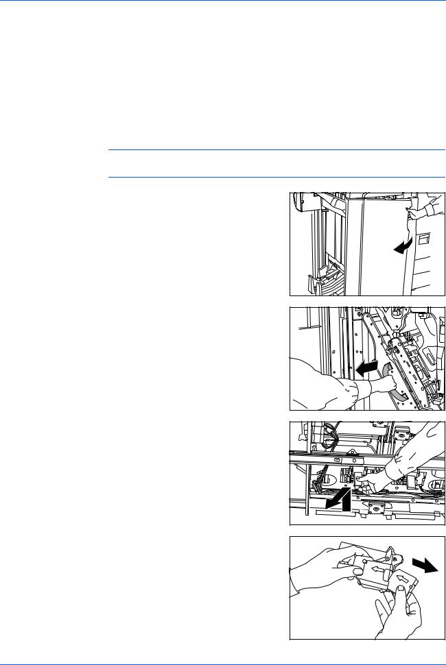
1 |
Grasp the front cover handle and open the |
|
front cover. |
2 |
Turn the unit release lever (G6), and then |
|
hold the unit release handle (G7) and move |
the Center-Folding Unit in the paper ejection direction.
3 |
If the jammed paper is visible from under the |
|
internal tray, remove the jammed paper. |
4 |
If paper is jammed inside the internal tray, |
|
remove the jammed paper using the |
instructions on page 1-23.
1-26 |
DF-650, MT-1(A), BF-1(A), PH-4A AND PH-4C OPERATION GUIDE |
Loading...