


SERVICE MANUAL
Published in Sep. ’01
842BL110
2BL70760
Revision 2.1
Revision history
Version |
Date |
Replaced pages |
Remarks |
|
|
|
|
1.0 |
July-2001 |
- |
- |
|
|
|
|
2.0 |
31-Jan-2002 |
- |
- |
|
|
|
|
2.1 |
3-Apr-2002 |
1-5-51 |
- |
|
|
|
|

Safety precautions
This booklet provides safety warnings and precautions for our service personnel to ensure the safety of their customers, their machines as well as themselves during maintenance activities. Service personnel are advised to read this booklet carefully to familiarize themselves with the warnings and precautions described here before engaging in maintenance activities.

Safety warnings and precautions
Various symbols are used to protect our service personnel and customers from physical danger and to prevent damage to their property. These symbols are described below:
 DANGER: High risk of serious bodily injury or death may result from insufficient attention to or incorrect compliance with warning messages using this symbol.
 WARNING:Serious bodily injury or death may result from insufficient attention to or incorrect compliance with warning messages using this symbol.
 CAUTION: Bodily injury or damage to property may result from insufficient attention to or incorrect compliance with warning messages using this symbol.
Symbols
The triangle ( ) symbol indicates a warning including danger and caution. The specific point of attention is shown inside the symbol.
General warning.
Warning of risk of electric shock.
Warning of high temperature.
 indicates a prohibited action. The specific prohibition is shown inside the symbol.
General prohibited action.
Disassembly prohibited.
 indicates that action is required. The specific action required is shown inside the symbol.
General action required.
Remove the power plug from the wall outlet.
Always ground the printer.

1. Installation Precautions
 WARNING
•Do not use a power supply with a voltage other than that specified. Avoid multiple connections to one outlet: they may cause fire or electric shock. When using an extension cable, always check that it is adequate for the rated current. ............................................................................................
•Connect the ground wire to a suitable grounding point. Not grounding the printer may cause fire or electric shock. Connecting the earth wire to an object not approved for the purpose may cause explosion or electric shock. Never connect the ground cable to any of the following: gas pipes, lightning rods, ground cables for telephone lines and water pipes or faucets not approved by the proper authorities. .............................................................................................................................
 CAUTION:
•Do not place the printer on an infirm or angled surface: the printer may tip over, causing injury. ....
•Do not install the printer in a humid or dusty place. This may cause fire or electric shock. ..............
•Do not install the printer near a radiator, heater, other heat source or near flammable material. This may cause fire. ..........................................................................................................................
•Allow sufficient space around the printer to allow the ventilation grills to keep the machine as cool as possible. Insufficient ventilation may cause heat buildup and poor copying performance. ..........
•Always handle the machine by the correct locations when moving it. ..............................................
•Always use anti-toppling and locking devices on printers so equipped. Failure to do this may cause the printer to move unexpectedly or topple, leading to injury. ................................................
•Avoid inhaling toner or developer excessively. Protect the eyes. If toner or developer is accidentally ingested, drink a lot of water to dilute it in the stomach and obtain medical attention immediately. If it gets into the eyes, rinse immediately with copious amounts of water and obtain medical attention. ..............................................................................................................................
•Advice customers that they must always follow the safety warnings and precautions in the printer’s instruction handbook. ..........................................................................................................

2. Precautions for Maintenance
 WARNING
•Always remove the power plug from the wall outlet before starting machine disassembly. .............
•Always follow the procedures for maintenance described in the service manual and other related brochures. .........................................................................................................................................
•Under no circumstances attempt to bypass or disable safety features including safety mechanisms and protective circuits. .................................................................................................
•Always use parts having the correct specifications. ..........................................................................
•Always use the thermostat or thermal fuse specified in the service manual or other related brochure when replacing them. Using a piece of wire, for example, could lead to fire or other serious accident. ...............................................................................................................................
•When the service manual or other serious brochure specifies a distance or gap for installation of a part, always use the correct scale and measure carefully. ...............................................................
•Always check that the printer is correctly connected to an outlet with a ground connection. ...........
•Check that the power cable covering is free of damage. Check that the power plug is dust-free. If it is dirty, clean it to remove the risk of fire or electric shock. ............................................................
•Never attempt to disassemble the optical unit in machines using lasers. Leaking laser light may damage eyesight. ..............................................................................................................................
•Handle the charger sections with care. They are charged to high potentials and may cause electric shock if handled improperly. .................................................................................................
 CAUTION
•Wear safe clothing. If wearing loose clothing or accessories such as ties, make sure they are safely secured so they will not be caught in rotating sections. .........................................................
•Use utmost caution when working on a powered machine. Keep away from chains and belts. .......
•Handle the fixing section with care to avoid burns as it can be extremely hot. .................................
•Check that the fixing unit thermistor, heat and press rollers are clean. Dirt on them can cause abnormally high temperatures. .........................................................................................................
•Do not remove the ozone filter, if any, from the printer except for routine replacement. ..................

•Do not pull on the AC power cord or connector wires on high-voltage components when removing them; always hold the plug itself. ......................................................................................................
•Do not route the power cable where it may be stood on or trapped. If necessary, protect it with a cable cover or other appropriate item. ..............................................................................................
•Treat the ends of the wire carefully when installing a new charger wire to avoid electric leaks. ......
•Remove toner completely from electronic components. ...................................................................
•Run wire harnesses carefully so that wires will not be trapped or damaged. ...................................
•After maintenance, always check that all the parts, screws, connectors and wires that were removed, have been refitted correctly. Special attention should be paid to any forgotten connector, trapped wire and missing screws. ..................................................................................
•Check that all the caution labels that should be present on the machine according to the instruction handbook are clean and not peeling. Replace with new ones if necessary. ...................
•Handle greases and solvents with care by following the instructions below: ....................................
·Use only a small amount of solvent at a time, being careful not to spill. Wipe spills off completely.
·Ventilate the room well while using grease or solvents.
·Allow applied solvents to evaporate completely before refitting the covers or turning the main switch on.
·Always wash hands afterwards.
•Never dispose of toner or toner bottles in fire. Toner may cause sparks when exposed directly to fire in a furnace, etc. .........................................................................................................................
•Should smoke be seen coming from the printer, remove the power plug from the wall outlet immediately. ......................................................................................................................................
3. Miscellaneous
 WARNING
•Never attempt to heat the drum or expose it to any organic solvents such as alcohol, other than the specified refiner; it may generate toxic gas. ................................................................................
|
|
CONTENTS |
|
1-1 Specifications |
|
||
1-1-1 |
Specifications ........................................................................................................................................... |
1-1-1 |
|
1-1-2 |
Parts names ............................................................................................................................................. |
1-1-3 |
|
|
(1) |
Printer ............................................................................................................................................... |
1-1-3 |
|
(2) |
Operator panel .................................................................................................................................. |
1-1-4 |
1-1-3 |
Machine cross section .............................................................................................................................. |
1-1-5 |
|
1-1-4 |
Drive system ............................................................................................................................................. |
1-1-6 |
|
|
(1) |
Drive system 1 (drive motor and eject motor drive trains) ................................................................ |
1-1-6 |
|
(2) |
Drive system 2 (paper feed motor drive train) ................................................................................... |
1-1-7 |

FS-9100DN/9500DN
1-1-1 Specifications
Type ............................................... |
Desktop laser printer |
Printing system ............................... |
Electro photographic system |
Paper .............................................. |
Cassette: Plain paper (60 to 90 g/m2) |
|
MP tray: Plain paper (60 to 90 g/m2), Thick paper (90 to 200 g/m2) |
|
Special paper: Transparencies, tracing paper, colored paper, letterhead and |
|
envelopes |
|
Note: Use the MP tray for special paper. |
Printing sizes .................................. |
Maximum: A3/Ladger |
|
Minimum: A5R /51/2" × 81/2" (When the MP tray is used) |
Print speed ..................................... |
FS-9100DN model [Cassette/MP tray] |
|
A4: 36 pages/33 pages per min. |
|
B4: 22 pages/19 pages per min. |
|
A3: 19 pages/16 pages per min. |
|
Letter: 36 pages/33 pages per min. |
|
Legal: 22 pages/19 pages per min. |
|
Ledger: 19 pages/16 pages per min. |
|
Duplex print |
|
A4/Letter: 29 pages per min. |
|
FS-9500DN model [Cassette/MP tray] |
|
A4: 50 pages/46 pages per min. |
|
B4: 31 pages/27 pages per min. |
|
A3: 26 pages/22 pages per min. |
|
Letter: 50 pages/46 pages per min. |
|
Legal: 31 pages/27 pages per min. |
|
Ledger: 26 pages/22 pages per min. |
|
Duplex print |
|
A4/Letter: 37 pages per min. |
First print time ................................ |
7 s or less (A4, Ecopower mode off) |
|
67 s or less (A4, Ecopower mode on) |
Warm-up time ................................. |
60 s or less (room temperature 23 °C/73.4 °F, 60% RH) |
Paper feed system ......................... |
2 universal type cassettes, and MP tray |
Paper loading capacity ................... |
Cassette: 500 sheets (80 g/m2, 0.11 mm) |
|
MP tray: 200 sheets (80 g/m2, 0.11 mm) |
Printout stacking capacity .............. |
Face down tray: 500 sheets with paper full sensor |
Photoconductor .............................. |
aSi drum (diameter 40 mm) |
Charging system ............................ |
Single positive corona charging |
Exposure light source .................... |
Semiconductor laser |
Exposure scanning system ............ |
Polygon mirror |
Developing system ......................... |
Dry, reverse developing (magnetic brush) |
|
Developer: 1-component, magnetism toner |
|
Toner replenishing: automatic from a toner container |
Transfer system ............................. |
Transfer roller |
Separation system ......................... |
Separation electrode |
Fixing system ................................. |
Heat roller and press roller |
|
Heat source: halogen heaters (120 V specifications: main 600 W, sub 400 W/220-240 |
|
V specifications: main 600 W, sub 420 W, |
|
Control temperature: 165 °C/329 °F (at normal ambient temperature) |
|
Abnormally high temperature protection device: 170 °C/338 °F thermostats |
|
Fixing pressure: 107.8 N |
Charge erasing system .................. |
Exposure by cleaning lamp (LED array) |
Cleaning system ............................ |
Cleaning blade |
Controller hardware ....................... |
CPU: Power PC750CX 350 MHz (FS-9100DN model) |
|
Power PC750CX 400 MHz (FS-9500DN model) |
|
Code ROM: 4 MB (2 system DIMM PWBs in sockets) |
|
Font ROM: 4 MB (PCL6 and KPDL3) |
|
Main RAM: 32 MB (standard) |
|
Option expanding RAM: 2 sockets (Maximum 288 MB, including the standard RAM) |
|
Option memory card: 1 slot (CompactFlash card) |
|
Option interface: 2 slots (KUIO-LV) |
1-1-1

FS-9100DN/9500DN |
|
Host computer interface ................. |
Parallel: Bi-directional parallel (IEEE 1284 Nibble/ECP mode) |
|
Serial: RS-232C |
|
Network: 10Base-T/100Base-TX |
|
Option network interface card (KUIO slot No. 2): 10Base-T/100Base-TX/10Base-2 |
Controller software ......................... |
Emulation: PCL6, KPDL3, KCGL |
|
Fonts: PCL6, KPDL3 |
Smoothing ...................................... |
KIR |
Toner saving ................................... |
EcoPrint mode |
Resolution ...................................... |
Fast 1200 mode with KIR, 600 dpi with KIR, 300 dpi with KIR |
Dimensions .................................... |
Printer main unit: 585 (W) × 639 (D) × 615 (H) mm |
|
231/16" (W) × 253/16" (D) × 243/16" (H) |
|
Paper feeder PF-70: 560 (W) × 566 (D) × 251 (H) mm |
|
215/8" (W) × 221/16" (D) × 1715/16" (H) |
|
Paper feeder PF-75: 560 (W) × 566 (D) × 251 (H) mm |
|
215/8" (W) × 221/16" (D) × 1715/16" (H) |
Weight ............................................ |
Printer main unit: 52.5 kg/115.5 lbs (including toner containers) |
|
Paper feeder PF-70: 19.1 kg/42 lbs |
|
Paper feeder PF-75: 22.1 kg/48.6 lbs |
Floor requirements ......................... |
891 (W) × 560 (D) mm |
|
351/16" (W) × 221/16" (D) |
Functions ........................................ |
Self-diagnostics, sleep mode (energy saving) |
Power source ................................. |
120 V AC, 60 Hz, Max. 10.8 A/10.9 A (FS-9100DN/9500DN) |
|
220 - 240 V AC, 50/60 Hz, Max. 5.6 A/5.7 A (FS-9100DN/9500DN) |
Power consumption ....................... |
Maximum: 1400 W |
|
Printing: 680 W/790 W (FS-9100DN/9500DN) |
|
Ready: 140 W/150 W (FS-9100DN/9500DN) |
|
Sleep mode: 16 W or less |
Options ........................................... |
Expanding DIMM (16/32/64/128 MB), compact flash card, hard disk unit HD-3, paper |
|
feeder PF-70/75, finisher DF-70/75, barcode reader, network interface card IB-20/21/ |
|
21E |
1-1-2
FS-9100DN/9500DN
1-1-2 Parts names
(1) Printer |
! @ |
1 0
# $ % ^
2
3
4
|
‹ |
& |
¤ |
|
⁄ |
|
) |
|
( |
* |
|
|
Figure 1-1-1 |
1 Operator panel |
^ Cleaning brush |
2 Front cover |
& Power cord |
3 Lower paper cassette |
* Power cord connector |
4 Paper guide |
( Option unit connector |
5 Paper stopper |
) Handles for transport |
6 Upper paper cassette |
⁄ Side cover |
7 Handles for transport |
¤ Conveying cover lock lever |
8 MP (Multi-Purpose) tray |
‹ Conveying cover |
9 Power switch |
› Parallel cable connector |
0 Face-down tray |
fi Network cable connector |
! Toner container |
fl Serial cable connector |
@ Toner container release lever |
‡ Optional hard disk unit slot (OPT1/HDD) |
# Waste toner box |
— Optional network interface card slot (OPT2) |
$ Cleaning knob |
· Memory card slot |
% Main charger unit |
|
9
8
7
6
5
·
—
›
fi
fl
‡
1-1-3
FS-9100DN/9500DN
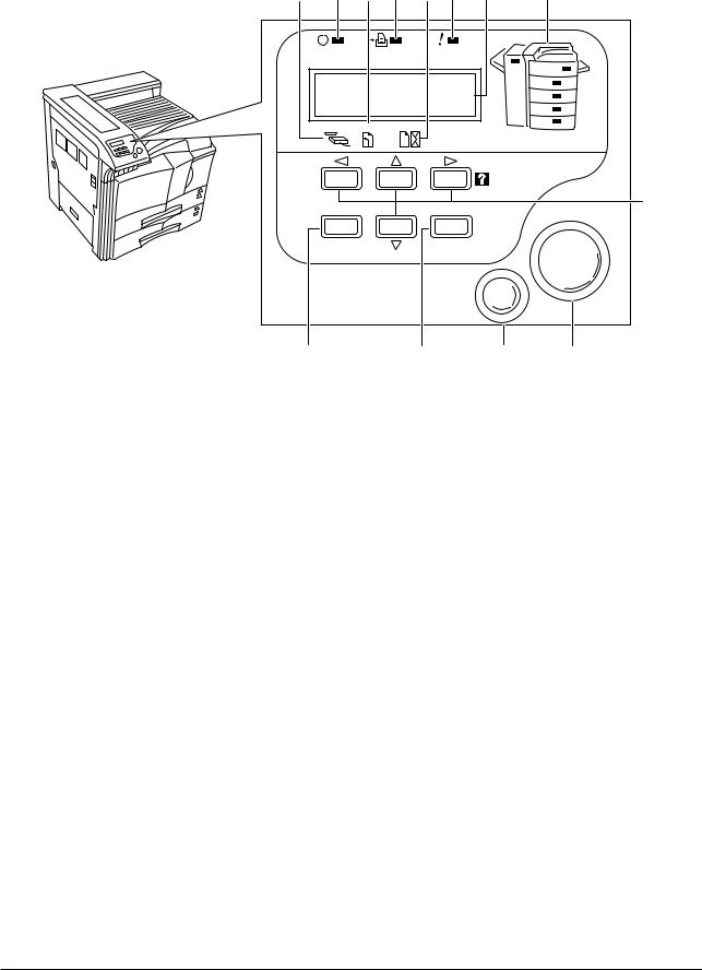
(2) Operator panel
0 6 ! 7 @ 8 9 #
READY |
DATA |
ATTENTION |
Ready |
|
--- |
A4 PLAIN |
INTERFACE SIZE |
TYPE |
5
GO
MENU ENTER
CANCEL
4 3 2 1
Figure 1-1-2
1 GO key
2 CANCEL key
3 ENTER key
4 MENU key
5 Arrow keys
6 Ready indicator
7 Data indicator
8 Attention indicator
9 Message display
0 Interface indicator ! Paper size indicator @ Paper type indicator
# Paper jam indicator
1-1-4
FS-9100DN/9500DN
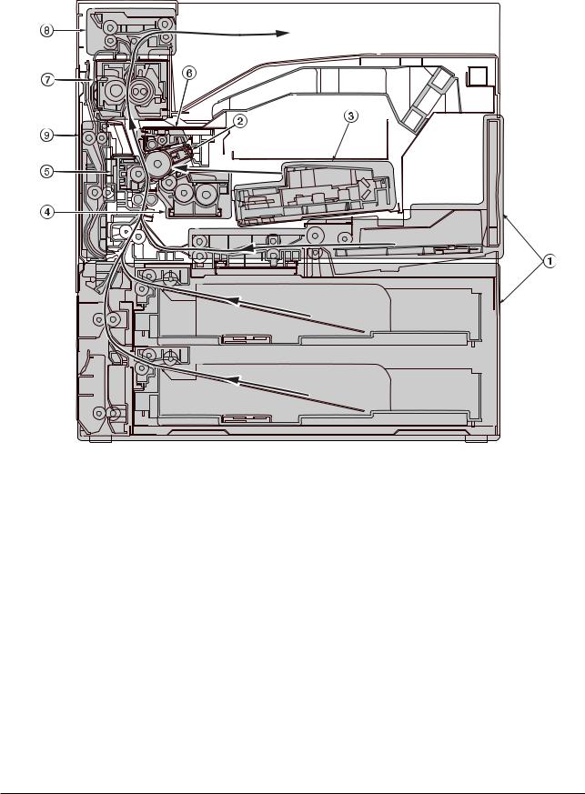
1-1-3 Machine cross section
 Light path
 Paper path
Figure 1-1-3 Machine cross section
1 Paper feed section
2 Main charging section
3 Laser scanner unit
4 Developing section
5 Transfer and paper conveying section
6 Cleaning and erasing section
7 Fuser section
8 Eject and switchback section
9 Duplex unit
1-1-5
FS-9100DN/9500DN
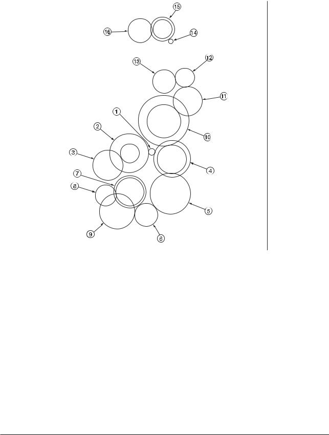
1-1-4 Drive system
(1) Drive system 1 (drive motor and eject motor drive trains)
As viewed from machine rear
Figure 1-1-4
1 Drive motor gear |
9 Registration clutch gear |
2 Drum gear Z76H/Z30H |
0 Gear Z63H/Z45S |
3 Drum gear Z70H |
! Gear Z37S |
4 Gear Z76H/Z35H |
@ Gear Z24S |
5 Gear Z50H |
# Joint gear Z32S |
6 Gear Z36S/Z31H |
$ Eject motor gear |
7 Gear Z37H/28H |
% Gear Z47S/Z28S |
8 Gear Z34H |
^ Eject gear Z30S |
1-1-6
FS-9100DN/9500DN
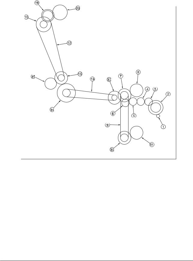
(2) Drive system 2 (paper feed motor drive train)
|
As viewed from machine rear |
Figure 1-1-5 |
|
1 Paper feed motor gear |
! Lower paper feed clutch gear |
2 Gear Z76H/Z35S |
@ Gear Z41S/P15 |
3 Feed gear Z25 |
# Bypass drive belt |
4 Feed gear Z25 |
$ Gear Z60S/P20 |
5 Feed gear Z25 |
% Gear Z41S/P18 |
6 Feed gear Z25 |
^ Gear Z40S/Z32S |
7 Gear Z41S/Z24S/P30 |
& Container drive belt |
8 Upper paper feed clutch gear |
* Gear Z24S/P40 |
9 Paper feed drive belt |
( Gear Z40S/Z25S |
0 Gear Z41S/Z24S/P30 |
) Container gear |
1-1-7
|
|
CONTENTS |
1-2 Handling precautions |
|
|
1-2-1 |
Drum ......................................................................................................................................................... |
1-2-1 |
1-2-2 Toner ........................................................................................................................................................ |
1-2-1 |
|
1-2-3 |
Installation environment ........................................................................................................................... |
1-2-1 |
FS-9100DN/9500DN
1-2-1 Drum
Note the following when handling or storing the drum.
•When removing the image formation unit, never expose the drum surface to strong direct light.
•Keep the drum at an ambient temperature between –20 °C/–4 °F and 40 °C/104 °F and at a relative humidity not higher than 85% RH. Avoid abrupt changes in temperature and humidity.
•Avoid exposure to any substance which is harmful to or may affect the quality of the drum.
•Do not touch the drum surface with any object. Should it be touched by hands or stained with oil, clean it.
1-2-2 Toner
Store the toner in a cool, dark place. Avoid direct light and high humidity.
1-2-3 Installation environment
1.Temperature: 10 - 32.5 °C/50 - 90.5 °F
2.Humidity: 20 - 80 % RH
3.Power supply: 120 V AC ±10 %, 10.8 A/10.9 A (FS-9100DN/9500DN)
220 - 240 V AC 10 %, 5.6 A/5.7 A (FS-9100DN/9500DN)
4.Power source frequency: 50 Hz ±0.2 %/60 Hz ±0.2 %
5.Installation location
•Avoid direct sunlight or bright lighting. Ensure that the photoconductor will not be exposed to direct sunlight or other strong light when removing paper jams.
•Avoid extremes of temperature and humidity, abrupt ambient temperature changes, and hot or cold air directed onto the machine.
•Avoid dust and vibration.
•Choose a surface capable of supporting the weight of the machine.
•Place the machine on a level surface (maximum allowance inclination: 1 ° ).
•Avoid air-borne substances that may adversely affect the machine or degrade the photoconductor, such as mercury, acidic of alkaline vapors, inorganic gasses, NOx, SOx gases and chlorine-based organic solvents.
•Select a room with good ventilation.
6.Allow sufficient access for proper operation and maintenance of the machine.
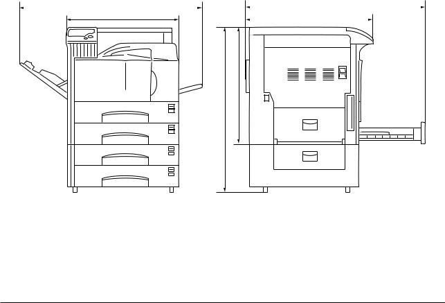
Machine front: 100 cm/393/8" |
Machine rear: 10 cm/315/16" |
|
|||
Machine right: 70 cm/279/16" |
Machine left: 60 cm/235/8" |
|
|||
|
d |
|
|
f |
|
|
|
|
|
|
|
|
a |
|
|
c |
|
b
e
a: 585 mm/231/16" |
d: 1032 mm/405/8" |
b: 615 mm/243/16" |
e: 920 mm/361/4" |
c: 665 mm/263/16" |
f: 1055 mm/419/16" |
Figure 1-2-1 |
Installation dimensions |
1-2-1
|
CONTENTS |
|
1-3 Installation |
|
|
1-3-1 Unpacking and installation ....................................................................................................................... |
1-3-1 |
|
|
(1) Installation procedure ........................................................................................................................ |
1-3-1 |
1-3-2 Installing the cassette heater (option) ...................................................................................................... |
1-3-9 |
|
1-3-3 |
Installing DIMMs (option) ......................................................................................................................... |
1-3-11 |
1-3-4 |
Installing the network interface card (option) .......................................................................................... |
1-3-12 |
1-3-5 |
Installing the hard disk (option) .............................................................................................................. |
1-3-13 |
1-3-6 |
Installing the memory card (option) ........................................................................................................ |
1-3-14 |
FS-9100DN/9500DN
1-3-1 Unpacking and installation
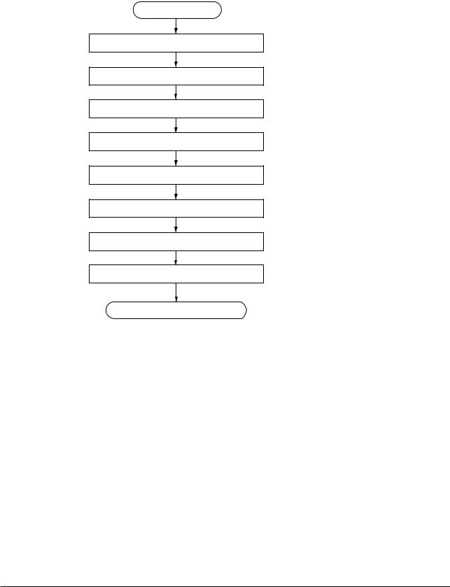
(1) Installation procedure
Start
Unpacking.
Removing the tapes.
Placing the proper location.
Installing the toner container.
Installing the waste toner box.
Connecting the printer to the computer.
Connecting the power cord.
Printing a status page for test.
Completion of the machine installation.
1-3-1

FS-9100DN/9500DN
 Unpacking.
Figure 1-3-1 Unpacking
Paper size plate (4)
Printer |
|
|
CD-ROM |
Toner container |
|
|
Installation guide |
|
Quick configuration guide |
Waste toner box |
(for network interface) |
|
|
|
Power cord |
|
(220-240 V models only) |
Figure 1-3-2 List of shipped components
1-3-2
 Removing the tapes.
1.Remove the tape holding the front cover.
2.Remove the tape holding the MP tray.
3.Remove the two tapes holding the paper cassettes.
4. Remove the tapes holding the conveying cover.
5.Pull out the upper paper cassette and remove the two tapes holding the bottom plate.
6.Pull out the lower paper cassette and remove the two tapes holding the bottom plate.
FS-9100DN/9500DN
Tape
 Tape
Tape

 Tapes
Tapes
Figure 1-3-3
Tape
Figure 1-3-4
Tape
Figure 1-3-5
1-3-3
FS-9100DN/9500DN
 Placing the proper location.
1. Place the printer in a proper location.
Rear: 10 cm (315/16") |
Right: |
70 cm (279/16") |
Left: |
60 cm (235/8") |
Front: 100 cm (393/8") |
Figure 1-3-6 |
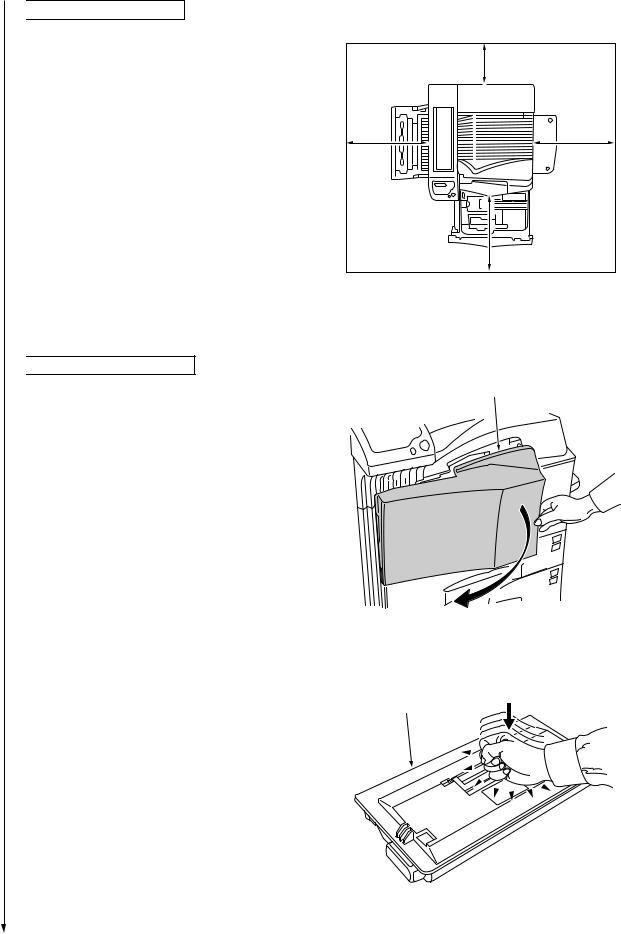
 Installing the toner container.
1. Open the printer front cover all the way. |
Front cover |
Figure 1-3-7
2. Take out the toner container from the bag. |
|
3. Tap the new toner container on the top 5 to 6 |
Toner container |
times. |
|
Figure 1-3-8
1-3-4
FS-9100DN/9500DN
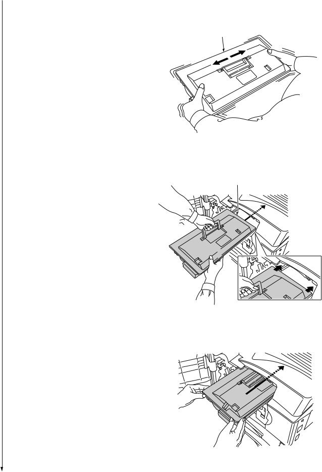
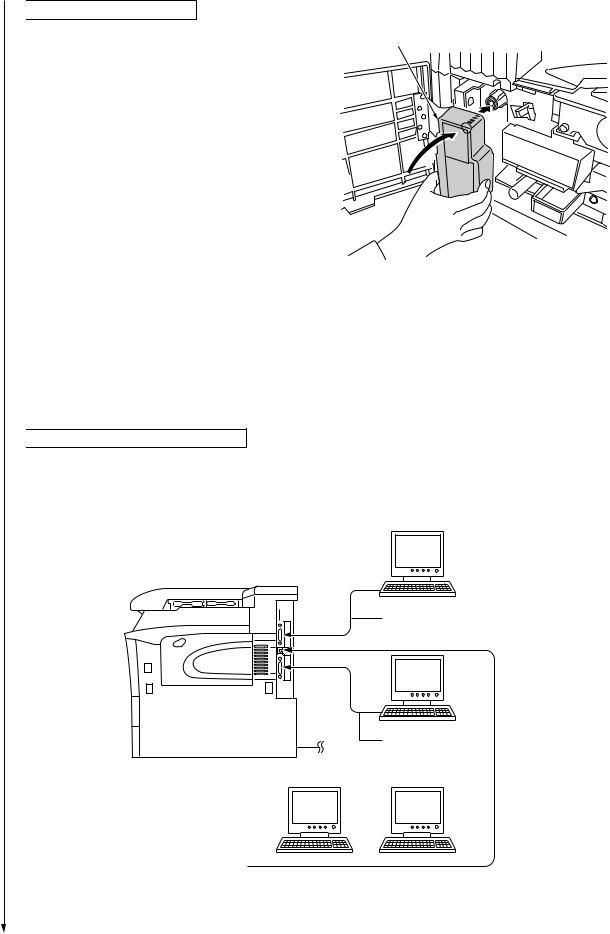
4.Thoroughly shake the toner container (in the directions of the arrows) ten times or more to loosen and mix the toner inside.
Toner container
5.Grasp the handle on the toner container and insert the toner container along the rail of the printer.
6.Hold the toner container by hands and fully insert it into the printer.
Figure 1-3-9
Toner container
Figure 1-3-10
Figure 1-3-11
1-3-5
FS-9100DN/9500DN
 Installing the waste toner box.
1. Install the waste toner box as shown in the figure.
Waste toner box
2. Close the front cover.
Figure 1-3-12
 Connecting the printer to the computer.
There are various ways of connecting the printer to the computer, such as through the parallel interface connecter, serial interface connecter, or through the network interface connecter.
Printer (Right side)
Parallel interface
Serial interface
Power cord |
|
|
Network |
||
|
|
|
|
|
|
|
|
|
|
|
|
|
|
|
|
|
|
Figure 1-3-13
1-3-6
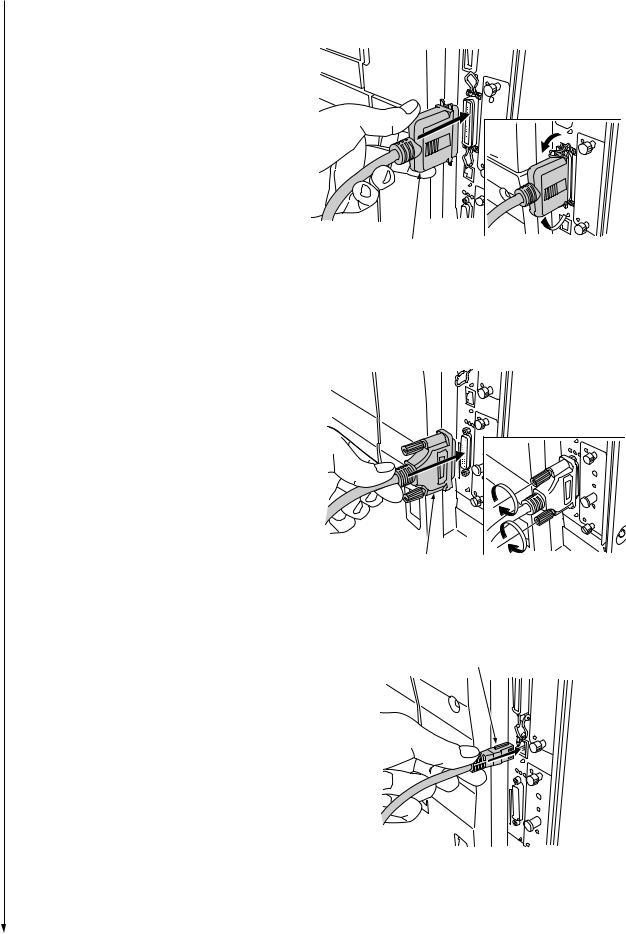
•Parallel interface connection
1.Plug one end of the printer cable (not included) into the parallel interface connection on the right side of the printer.
2.Close the clips on both sides to fix the connector in place.
Plug the other end of the printer cable Into the computer‘s parallel Interface connection.
•Serial interface connection
1.Plug one end of the printer cable (not Included) Into the serial Interface connection on the right side of the printer.
2.Securely tighten the screws on both sides of the connecter.
Plug the other end of the printer cable Into the computer‘s serial Interface connection.
•Network interface connection
1.Plug the network cable (not included) into the network interface connection on the right side of printer.
FS-9100DN/9500DN
Parallel printer cable
Figure 1-3-14
Serial printer cable
Figure 1-3-15
Network cable
Figure 1-3-16
1-3-7
FS-9100DN/9500DN
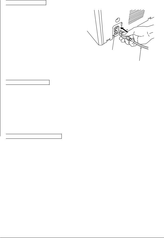
 Connecting the power cord.
1.Plug the power cord into the power cord connector on the rear of the printer. (220 - 240 V models only)
2.Connect the other end of the power cord into a power outlet.
Power cord connector (220 - 240 V models only)
Power cord
Figure 1-3-17
 Printing a status page for test.
1.Add paper in the paper cassette.
2.Turn on the printer power switch.
"Adding toner" will be displayed and the toner supply action will be taken for about 8 minutes.
3.Press the MENU key on the operation panel.
4.Press the  or
or  key repeatedly until [Print Status page] is displayed.
5.Press the ENTER key twice. A status page is printed.
 Completion of the machine installation.
1-3-8
FS-9100DN/9500DN
1-3-2 Installing the cassette heater (option)
Cassette heater installation requires the following parts:
•Cassette heater (P/N 34860030): for 120 V specifications
•Cassette heater (P/N 33960020): for 220 - 240 V specifications
•Binding band (P/N M2107120)
•Two binding screws BVM4X6 (P/N B1304060)
•Caution label (P/N 20305130)
•Fax kit label (P/N 3CM05010)
Screws
Procedure |
Aperture |
1. Pull the upper and lower cassettes out.
2. Install the cassette heater to the bottom of the machine with two screws (M4X06), and bind
the wire of the cassette heater with the band.
3. Put the wire of the cassette heater out of the machine through the aperture of the rear frame.
4. Stick the caution label in front of the cassette
heater.
Caution label
Band
Cassette heater
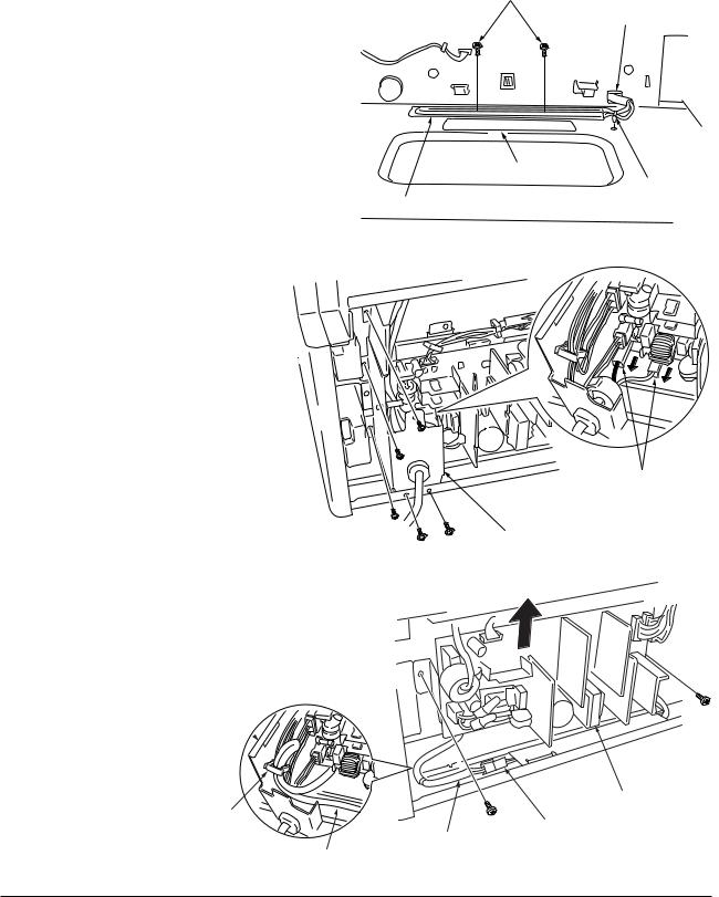
5.Remove the five screws and the two connectors and then remove the power supply mount from the rear side of the
machine.
Pay attention not to reverse the black wire and white wire when refitting the connector.
6.Remove the two screws and pull out the wire of the cassette heater that has been put out of the rear frame while raising the power supply unit.
7.Insert the connector of the cassette heater into the connector of the machine.
8.Fold the wire of the cassette heater and insert it into the clamp of the power supply mount as shown in the figure.
Power supply mount 
Clump
Wire of the cassette heater
Figure 1-3-18
Connectors
Power supply mount
Figure 1-3-19
Power supply unit
Connector
Wire of the cassette heater
Figure 1-3-20
1-3-9

FS-9100DN/9500DN
9.Stick the label below the power switch.
10.Refit all the removed parts.
Label
Figure 1-3-21
1-3-10
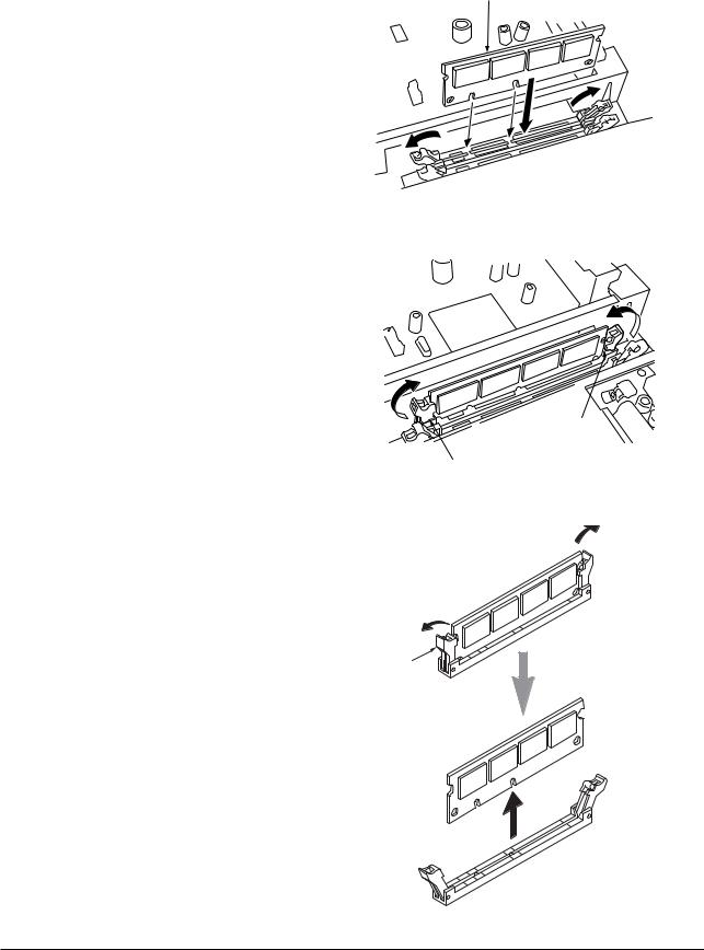
1-3-3 Installing DIMMs (option)
Procedure
•Installing DIMM
1.Remove two screws and then remove the main controller PWB (see page 1-6-24).
2.Open the clips on both ends of the DIMM socket.
3.Insert the DIMM into the socket, so that the notches on the DIMM align with the corresponding protrusions in the socket.
4.Close the clips of the DIMM socket to secure the DIMM.
5.When you finish installing the DIMM, reinsert the main controller PWB into the printer.
•Removing DIMM
1.To remove a DIMM, carefully pull the end clips outwards, then pull the DIMM out of the socket.
FS-9100DN/9500DN
DIMM
Figure 1-3-22
Clip
Clip
Figure 1-3-23
 Clip
Clip
Clip
Figure 1-3-24
1-3-11
FS-9100DN/9500DN
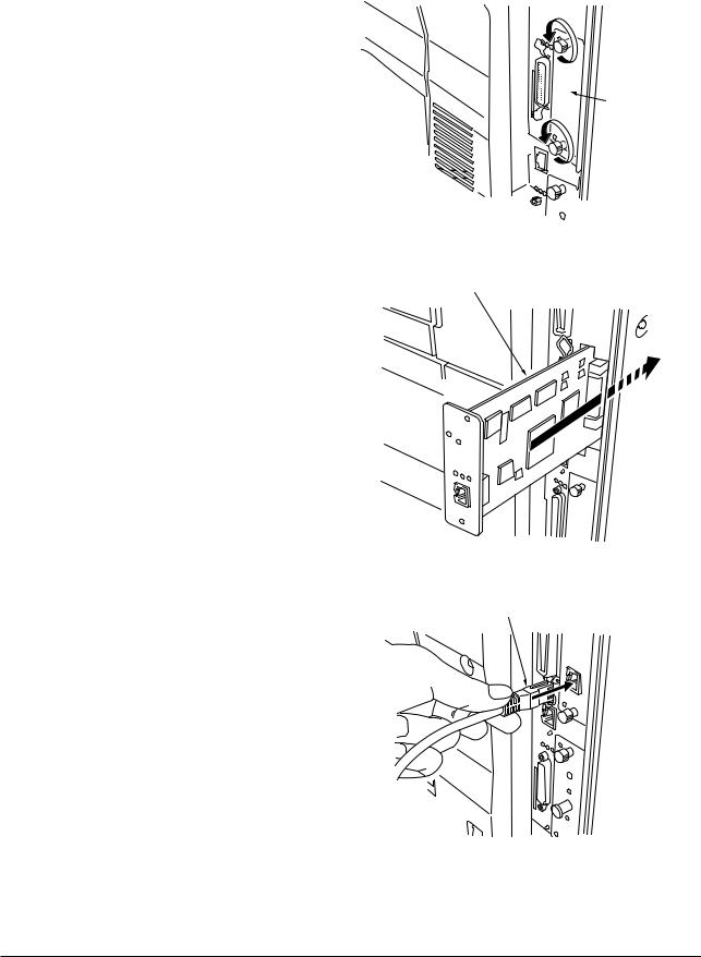
1-3-4 Installing the network interface card (option)
Procedure
1.Remove the two screws from the option interface slot cover.
Option interface slot cover
|
Figure 1-3-25 |
2. Insert the network interface card and secure it |
Network interface card |
with the screws removed in step 1. |
|
Figure 1-3-26
Network cable
3. Connect the network cable.
Figure 1-3-27
1-3-12
 Loading...