


 Loading...
SERVICE MANUAL
COMPACT COMPONENT SYSTEM
DX-U10A, DX-U10US, DX-U10UX, DX-U10UG, DX-U10UN, DX-U8US, DX-U8UX, DX-U8UG, DX-U8UN, DX-U6US, DX-U6UX, DX-U6UG, DX-U6UN, DX-U10UH
SP-DXU10W CA-DXU10 SP-DXU10W SP-DXU10C SP-DXU10S SP-DXU10F SP-DXU10F SP-DXU10S
SP-DXU10W CA-DXU8 SP-DXU8S
SP-DXU8S |
SP-DXU10F |
SP-DXU10F SP-DXU10C |
|
|
|
|
|
|
SUPER VIDEO
SUPER VIDEO
SP-DXU10W CA-DXU6
SP-DXU6F SP-DXU6F
Lead free solder used in the board (material : Sn-Ag-Cu, melting point : 219 Centigrade) Lead free solder used in the board (material : Sn-Cu, melting point : 230 Centigrade)
TABLE OF CONTENTS
1 PRECAUTION. . . . . . . . . . . . . . . . . . . . . . . . . . . . . . . . . . . . . . . . . . . . . . . . . . . . . . . . . . . . . . . . . . . . . . . . . 1-4 2 SPECIFIC SERVICE INSTRUCTIONS . . . . . . . . . . . . . . . . . . . . . . . . . . . . . . . . . . . . . . . . . . . . . . . . . . . . . . 1-7 3 DISASSEMBLY . . . . . . . . . . . . . . . . . . . . . . . . . . . . . . . . . . . . . . . . . . . . . . . . . . . . . . . . . . . . . . . . . . . . . . . 1-8 4 ADJUSTMENT . . . . . . . . . . . . . . . . . . . . . . . . . . . . . . . . . . . . . . . . . . . . . . . . . . . . . . . . . . . . . . . . . . . . . . . 1-34 5 TROUBLESHOOTING . . . . . . . . . . . . . . . . . . . . . . . . . . . . . . . . . . . . . . . . . . . . . . . . . . . . . . . . . . . . . . . . . 1-35
COPYRIGHT © 2008 Victor Company of Japan, Limited
No.MB616<Rev.002>
2008/4
SPECIFICATION
DX-U10/DX-U8
Amplifier section |
Output Power |
FRONT SPEAKERS |
|
150 W per channel, min. RMS, driven into 4 Ω at 1 kHz with |
|
|
|
|
no more than 10% total harmonic distortion. |
|
|
CENTER SPEAKER |
CA-DXU10 |
140 W per channel, min. RMS, driven into 6 Ω at 1 kHz with |
|
|
|
|
no more than 10% total harmonic distortion. |
|
|
|
CA-DXU8 |
50 W per channel, min. RMS, driven into 6 Ωat 1 kHz with no |
|
|
|
|
more than 10% total harmonic distortion. |
|
|
SURROUND SPEAKERS |
CA-DXU10 |
130 W per channel, min. RMS, driven into 6 Ω at 1 kHz with |
|
|
|
|
no more than 10% total harmonic distortion. |
|
|
|
CA-DXU8 |
50 W per channel, min. RMS, driven into 6 Ωat 1 kHz with no |
|
|
|
|
more than 10% total harmonic distortion. |
|
|
SUBWOOFERS |
|
150 W, min. RMS, driven into 4 Ω at 63 Hz with no more than |
|
|
|
|
10% total harmonic distortion. |
|
Digital output |
OPTICAL DIGITAL OUTPUT |
-21 dBm to -15 dBm (660 nm ±30 nm) |
|
|
Digital input |
|
|
USB memory |
|
Audio input sensitivity/ |
AUX(STEREO) |
|
400 mV/47 kΩ |
|
Impedance |
MIC1/MIC2 |
|
3.0 mV/50 kΩ |
|
VIDEO OUT |
Color system |
|
PAL/PAL PROG/NTSC/NTSC PROG selectable |
|
|
VIDEO (composite) |
|
1 V(p-p)/75 Ω |
|
|
S-VIDEO |
|
Y (luminance) : 1 V(p-p)/75 Ω |
|
|
|
|
C (chrominance, burst) : PAL : 0.3 V(p-p)/75 Ω |
|
|
|
|
C (chrominance, burst) : NTSC : 0.286 V(p-p)/75 Ω |
|
|
COMPONENT |
|
(Y) : 1 V(p-p)/75 Ω |
|
|
(Interlace/Progressive) |
|
(PB/PR) : 0.7 V(p-p)/75 Ω |
|
Speaker Terminals |
|
|
4 Ω - 16 Ω (front speakers/subwoofers) |
|
|
|
|
6 Ω - 16 Ω (surround/center speakers) |
Tuner section |
FM tuning range |
|
|
87.50 MHz - 108.00 MHz |
|
AM (MW) tuning range |
|
|
531 kHz - 1 710 kHz (at 9 kHz) |
|
|
|
|
530 kHz - 1 710 kHz (at 10 kHz) |
|
AM (MW) tuning range for Saudi Arabia |
|
531 kHz to 1 602 kHz (9 kHz) |
|
|
|
|
|
530 kHz to 1 600 kHz (10 kHz) |
Disc/file player section |
Region codes |
|
|
Middle East: 2 |
|
|
|
|
South East Asia: 3 |
|
|
|
|
Central and South America, Australia: 4 |
|
Playable disc |
|
|
DVD Video/DVD Audio/CD/VCD/SVCD |
|
|
|
|
CD-R/CD-RW (CD/VCD/SVCD/MP3/WMA/WAV/JPEG/ |
|
|
|
|
MPEG-1/MPEG-2/ASF/DivX format) |
|
|
|
|
CD-ROM (MP3/WMA/WAV/JPEG/MPEG-1/MPEG-2/ASF/ |
|
|
|
|
DivX format) |
|
|
|
|
DVD-R/-RW (DVD-VR/DVD Video/DVD Audio/MP3/WMA/ |
|
|
|
|
WAV/JPEG/MPEG-1/MPEG-2/ASF/DivX format) |
|
|
|
|
+R/+RW (DVD Video/DVD Audio/MP3/WMA/WAV/JPEG/ |
|
|
|
|
MPEG-1/MPEG-2/ASF/DivX format) |
|
|
|
|
DVD-ROM (DVD Video/MP3/WMA/WAV/JPEG/MPEG-1/ |
|
|
|
|
MPEG-2/ASF/DivX format) |
|
Playable file |
|
|
MP3, WMA, WAV, JPEG, MPEG-1, MPEG-2, ASF, DivX for- |
|
|
|
|
mat |
|
Dynamic range |
|
|
80 dB |
|
Horizontal resolution |
|
|
500 lines |
|
Wow and flutter |
|
|
Immeasurable |
USB storage section |
USB specification |
|
|
Compatible with USB 2.0 Full Speed |
|
Compatible device |
|
|
Mass Storage Class |
|
Compatible file system |
|
|
FAT16, FAT32 |
|
Bus power supply |
|
|
5 V / 500 mA |
Cassette deck section |
Frequency response: Normal (type I) |
|
50 Hz - 14 000 Hz |
|
|
Wow and flutter |
|
|
0.15% (WRMS) |
General |
Power requirement |
|
|
AC 110 V / AC 127 V / AC 220 V / AC 230 V - AC 240 V , |
|
|
|
|
(adjustable with the voltage selector), 50 Hz / 60 Hz |
|
Power requirement: For Australia |
|
AC 240 V , 50 Hz |
|
|
Power consumption |
CA-DXU10 |
|
300 W (at operation) / 22 W (on standby) |
|
|
CA-DXU8 |
|
270 W (at operation) / 21 W (on standby) |
|
Dimensions (W/H/D) |
(approx.) |
|
185 mm × 460 mm × 370 mm |
|
Mass (approx.) |
CA-DXU10 |
|
11.5 kg |
|
|
CA-DXU8 |
|
11.4 kg |
Measured at 1 kHz, with tape recording signal 400 mV
Design and specifications are subject to change without notice.
1-2 (No.MB616<Rev.002>)
DX-U6
Amplifier section |
Output Power |
FRONT SPEAKERS |
150 W per channel, min. RMS, driven into 4 Ω at 1 kHz with no more |
|
|
|
than 10% total harmonic distortion. |
|
|
|
|
|
|
SUBWOOFER |
150 W, min. RMS, driven into 4 Ω at 63 Hz with no more than 10% total |
|
|
|
harmonic distortion. |
|
|
|
|
|
Digital output |
OPTICAL DIGITAL OUTPUT |
-21 dBm to -15 dBm (660 nm ±30 nm) |
|
|
|
|
|
Digital input |
|
USB memory |
|
|
|
|
|
Audio input sensitivity/ |
AUX |
400 mV/47 kΩ |
|
Impedance |
|
|
|
MIC1/MIC2 |
3.0 mV/50 kΩ |
|
|
|
||
|
|
|
|
|
VIDEO OUT |
Color system |
PAL/PAL PROG/NTSC/NTSC PROG selectable |
|
|
|
|
|
|
VIDEO (composite) |
1 V(p-p)/75 Ω |
|
|
|
|
|
|
S-VIDEO |
Y (luminance) : 1 V(p-p)/75 Ω |
|
|
|
C (chrominance, burst) : PAL : 0.3 V(p-p)/75 Ω |
|
|
|
C (chrominance, burst) : NTSC : 0.286 V(p-p)/75 Ω |
|
|
|
|
|
|
COMPONENT |
(Y) : 1 V(p-p)/75 Ω |
|
|
(Interlace/Progressive) |
(PB/PR) : 0.7 V(p-p)/75 Ω |
|
|
|
|
|
Speaker Terminals |
|
4 Ω - 16 Ω (main speakers/subwoofer) |
|
|
|
16 Ω - 32 Ω (matrix surround speakers) |
|
|
|
|
Tuner section |
FM tuning range |
|
87.50 MHz - 108.00 MHz |
|
|
|
|
|
AM (MW) tuning range |
|
531 kHz - 1 710 kHz (at 9 kHz) |
|
|
|
530 kHz - 1 710 kHz (at 10 kHz) |
|
|
|
|
|
AM (MW) tuning range: For Saudi Arabia |
531 kHz to 1 602 kHz (9 kHz) |
|
|
|
|
530 kHz to 1 600 kHz (10 kHz) |
|
|
|
|
Disc/file player section |
Region codes |
|
Middle East: 2 |
|
|
|
South East Asia: 3 |
|
|
|
Central and South America, Australia: 4 |
|
|
|
|
|
Playable disc |
|
DVD Video/DVD Audio/CD/VCD/SVCD |
|
|
|
CD-R/CD-RW (CD/VCD/SVCD/MP3/WMA/WAV/JPEG/MPEG-1/ |
|
|
|
MPEG-2/ASF/DivX format) |
|
|
|
CD-ROM (MP3/WMA/WAV/JPEG/MPEG-1/MPEG-2/ASF/DivX for- |
|
|
|
mat) |
|
|
|
DVD-R/-RW (DVD-VR/DVD Video/DVD Audio/MP3/WMA/WAV/ |
|
|
|
JPEG/MPEG-1/MPEG-2/ASF/DivX format) |
|
|
|
+R/+RW (DVD Video/DVD Audio/MP3/WMA/WAV/JPEG/MPEG-1/ |
|
|
|
MPEG-2/ASF/DivX format) |
|
|
|
DVD-ROM (DVD Video/MP3/WMA/WAV/JPEG/MPEG-1/MPEG-2/ |
|
|
|
ASF/DivX format) |
|
|
|
|
|
Playable file |
|
MP3, WMA, WAV, JPEG, MPEG-1, MPEG-2, ASF, DivX format |
|
|
|
|
|
Dynamic range |
|
80 dB |
|
|
|
|
|
Horizontal resolution |
|
500 lines |
|
|
|
|
|
Wow and flutter |
|
Immeasurable |
|
|
|
|
USB storage section |
USB specification |
|
Compatible with USB 2.0 Full Speed |
|
|
|
|
|
Compatible device |
|
Mass Storage Class |
|
|
|
|
|
Compatible file system |
|
FAT16, FAT32 |
|
|
|
|
|
Bus power supply |
|
5 V / 500 mA |
|
|
|
|
Cassette deck section |
Frequency response: Normal (type I) |
50 Hz - 14 000 Hz |
|
|
|
|
|
|
Wow and flutter |
|
0.15% (WRMS) |
|
|
|
|
General |
Power requirement |
|
AC 110 V / AC 127 V / AC 220 V / AC 230 V - AC 240 V , (adjustable |
|
|
|
with the voltage selector), 50 Hz / 60 Hz |
|
|
|
|
|
Power requirement: For Australia |
AC 240 V , 50 Hz |
|
|
|
|
|
|
Power consumption |
|
200 W (at operation) |
|
|
|
19 W (on standby) |
|
|
|
|
|
Dimensions (W/H/D) (approx.) |
185 mm × 460 mm × 370 mm |
|
|
|
|
|
|
Mass (approx.) |
|
10.5 kg |
|
|
|
|
Measured at 1 kHz, with tape recording signal 400 mV
Design and specifications are subject to change without notice.
(No.MB616<Rev.002>)1-3
SECTION 1 PRECAUTION
1.1Safety Precautions
(1)This design of this product contains special hardware and many circuits and components specially for safety purposes. For continued protection, no changes should be made to the original design unless authorized in writing by the manufacturer. Replacement parts must be identical to those used in the original circuits. Services should be performed by qualified personnel only.
(2)Alterations of the design or circuitry of the product should not be made. Any design alterations of the product should not be made. Any design alterations or additions will void the manufacturers warranty and will further relieve the manufacture of responsibility for personal injury or property damage resulting therefrom.
(3)Many electrical and mechanical parts in the products have special safety-related characteristics. These characteristics are often not evident from visual inspection nor can the protection afforded by them necessarily be obtained by using replacement components rated for higher voltage, wattage, etc. Replacement parts which have these special safety characteristics are identified in the Parts List of Service Manual. Electrical components having such features are identified by shading on the schematics and by (  ) on the Parts List in the Service Manual. The use of a substitute replacement which does not have the same safety characteristics as the recommended replacement parts shown in the Parts List of Service Manual may create shock, fire, or other hazards.
(4)The leads in the products are routed and dressed with ties, clamps, tubings, barriers and the like to be separated from live parts, high temperature parts, moving parts and/or sharp edges for the prevention of electric shock and fire hazard. When service is required, the original lead routing and dress should be observed, and it should be confirmed that they have been returned to normal, after reassembling.
(5)Leakage shock hazard testing
After reassembling the product, always perform an isolation check on the exposed metal parts of the product (antenna terminals, knobs, metal cabinet, screw heads, headphone jack, control shafts, etc.) to be sure the product is safe to operate without danger of electrical shock.Do not use a line isolation transformer during this check.
•Plug the AC line cord directly into the AC outlet. Using a "Leakage Current Tester", measure the leakage current from each exposed metal parts of the cabinet, particularly any exposed metal part having a return path to the chassis, to a known good earth ground. Any leakage current must not exceed 0.5mA AC (r.m.s.).
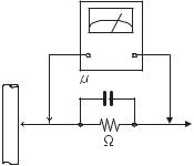
•Alternate check method
Plug the AC line cord directly into the AC outlet. Use an AC voltmeter having, 1,000Ω per volt or more sensitivity in the following manner. Connect a 1,500Ω 10W resistor paralleled by a 0.15µF AC-type capacitor between an exposed metal part and a known good earth ground.
Measure the AC voltage across the resistor with the AC
1-4 (No.MB616<Rev.002>)
voltmeter.
Move the resistor connection to each exposed metal part, particularly any exposed metal part having a return path to the chassis, and measure the AC voltage across the resistor. Now, reverse the plug in the AC outlet and repeat each measurement. Voltage measured any must not exceed 0.75 V AC (r.m.s.). This corresponds to 0.5 mA AC (r.m.s.).
|
AC VOLTMETER |
|
(Having 1000 |
|
ohms/volts, |
|
or more sensitivity) |
0.15 F AC TYPE |
|
|
Place this |
|
probe on |
1500 10W |
each exposed |
metal part. |
|
Good earth ground
1.2Warning
(1)This equipment has been designed and manufactured to meet international safety standards.
(2)It is the legal responsibility of the repairer to ensure that these safety standards are maintained.
(3)Repairs must be made in accordance with the relevant safety standards.
(4)It is essential that safety critical components are replaced by approved parts.
(5)If mains voltage selector is provided, check setting for local voltage.
1.3Caution
Burrs formed during molding may be left over on some parts of the chassis.
Therefore, pay attention to such burrs in the case of preforming repair of this system.
1.4Critical parts for safety
In regard with component parts appearing on the silk-screen printed side (parts side) of the PWB diagrams, the parts that are printed over with black such as the resistor (  ), diode (
  ) and ICP (
  ) or identified by the "
  " mark nearby are critical for safety. When replacing them, be sure to use the parts of the same type and rating as specified by the manufacturer.
(This regulation dose not Except the J and C version)
1.5Preventing static electricity
Electrostatic discharge (ESD), which occurs when static electricity stored in the body, fabric, etc. is discharged, can destroy the laser diode in the traverse unit (optical pickup). Take care to prevent this when performing repairs.
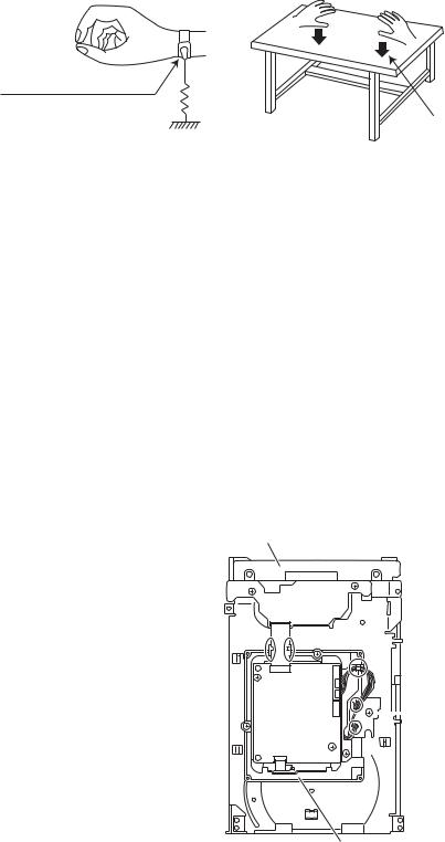
1.5.1Grounding to prevent damage by static electricity
Static electricity in the work area can destroy the optical pickup (laser diode) in devices such as laser products. Be careful to use proper grounding in the area where repairs are being performed.
(1)Ground the workbench
Ground the workbench by laying conductive material (such as a conductive sheet) or an iron plate over it before placing the traverse unit (optical pickup) on it.
(2)Ground yourself
Use an anti-static wrist strap to release any static electricity built up in your body.
(caption)
Anti-static wrist strap
1M
Conductive material (conductive sheet) or iron palate
(3)Handling the optical pickup
•In order to maintain quality during transport and before installation, both sides of the laser diode on the replacement optical pickup are shorted. After replacement, return the shorted parts to their original condition.
(Refer to the text.)
•Do not use a tester to check the condition of the laser diode in the optical pickup. The tester's internal power source can easily destroy the laser diode.
1.6Handling the traverse unit (optical pickup)
(1)Do not subject the traverse unit (optical pickup) to strong shocks, as it is a sensitive, complex unit.
(2)Cut off the shorted part of the flexible cable using nippers, etc. after replacing the optical pickup. For specific details, refer to the replacement procedure in the text. Remove the anti-static pin when replacing the traverse unit. Be careful not to take too long a time when attaching it to the connector.
(3)Handle the flexible cable carefully as it may break when subjected to strong force.
(4)I t is not possible to adjust the semi-fixed resistor that adjusts the laser power. Do not turn it.
1.7Attention when traverse unit is decomposed
*Please refer to "Disassembly method" in the text for the pickup unit.
•Apply solder to the short land sections before the card wire is disconnected from the connecto on the servo board. (If the card wire is disconnected without applying solder, the pickup may be destroyed by static electricity.)
•In the assembly, be sure to remove solder from the short land sections after connecting the card wire.
DVD changer mechanism assembly
 Switch board
DVD servo board 
DVD traverse mechanism assembly
(No.MB616<Rev.002>)1-5

1.8Important for laser products
1.CLASS 1 LASER PRODUCT
2.CAUTION :
(For U.S.A.) Visible and/or invisible class II laser radiation when open. Do not stare into beam.
(Others) Visible and/or invisible class 1M laser radiation when open. Do not view directly with optical instruments.
3.CAUTION : Visible and/or invisible laser radiation when open and inter lock failed or defeated. Avoid direct exposure to beam.
4.CAUTION : This laser product uses visible and/or invisible laser radiation and is equipped with safety switches which prevent emission of radiation when the drawer is open and the safety interlocks have failed or are defeated. It is dangerous to defeat the safety switches.
5.CAUTION : If safety switches malfunction, the laser is able to function.
6.CAUTION : Use of controls, adjustments or performance of procedures other than those specified here in may result in hazardous radiation exposure.
! |
|
|
|
|
Please use enough caution not to |
|||||||||||||
|
|
|
|
|
|
|
|
|
|
|
|
|
|
|
|
|
||
|
|
|
|
|
|
see the beam directly or touch it |
||||||||||||
|
|
|
|
|
|
in case of an adjustment or operation |
||||||||||||
|
|
|
|
|
|
check. |
||||||||||||
|
|
|
|
|
|
|
|
|
|
|
|
|
|
|
|
|
|
|
|
|
|
|
|
|
|
|
|
|
|
|
|
|
|
|
|
|
|
|
|
|
|
|
|
|
|
|
|
|
|
|
|
|
|
|
|
|
|
|
|
|
|
|
|
|
|
|
|
|
|
|
|
|
|
|
|
|
|
|
|
|
|
|
|
|
|
|
|
|
|
|
|
|
|
|
|
|
|
|
|
|
|
|
|
|
|
|
|
|
|
|
|
|
|
|
|
|
|
|
|
|
|
|
|
|
|
|
|
|
|
|
|
|
|
|
|
|
|
|
|
|
|
|
|
|
|
|
|
|
|
|
|
|
|
|
|
|
|
|
|
|
|
|
|
|
|
|
|
|
|
|
|
|
|
|
|
|
|
|
|
|
|
|
|
|
|
|
|
|
|
|
|
|
|
|
|
|
|
|
|
|
|
|
|
|
|
|
|
|
|
|
|
|
|
|
|
|
|
|
|
|
|
|
|
|
|
|
|
|
|
|
|
|
|
|
|
|
|
|
|
|
|
|
|
|
|
|
|
|
|
|
|
|
|
|
|
|
|
|
|
|
|
|
|
|
|
|
|
|
|
|
|
|
|
|
|
|
|
|
|
|
|
|
|
|
REPRODUCTION AND POSITION OF LABELS and PRINT
WARNING LABEL and PRINT
1-6 (No.MB616<Rev.002>)
SECTION 2
SPECIFIC SERVICE INSTRUCTIONS
This service manual does not describe SPECIFIC SERVICE INSTRUCTIONS.
(No.MB616<Rev.002>)1-7
SECTION 3
DISASSEMBLY
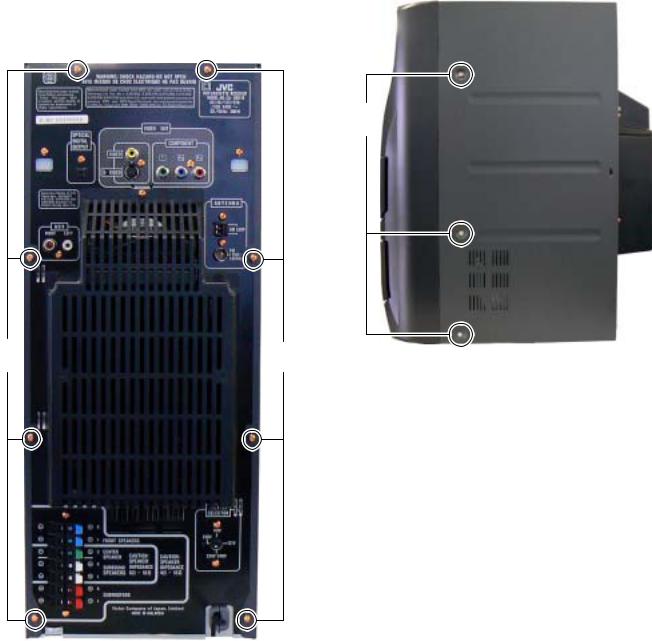
3.1Main body (Using figures are DX-U10)
3.1.1Removing the METAL COVER (See Fig.1, 2)
(1)Remove the eight screws A attaching the METAL COVER. (See Fig.1)
(2)Remove the six screws B attaching the both side of the METAL COVER. (See Fig.2)
B
A |
A |
Fig.2 |
|
|
Fig.1
1-8 (No.MB616<Rev.002>)
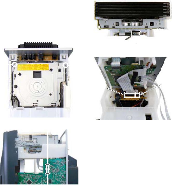
3.1.2 Removing the DVD CHANGER MECHANISM assembly (See Fig.3 to 6)
(1)Remove the two screws C attaching the DVD MECHANISM assembly. (See Fig.3)
(2)Disconnect the card wires from DVD MECHANISM assembly connected to connector CN800 and CN810 of the MAIN BOARD assembly. (See Fig.4)
(3)Disconnect the connector wire from USB board connected to connector CN811 of the DVD BOARD assembly. (See Fig.5)
(4)Disconnect the card wires from DVD BOARD assembly connected to connector CN921 and CN930 of the VIDEO board assembly. (See Fig.6)
C C
C
CN811 |
Fig.5
CN921
CN930
Fig.3
Fig.6
CN800
CN810
Fig.4
(No.MB616<Rev.002>)1-9
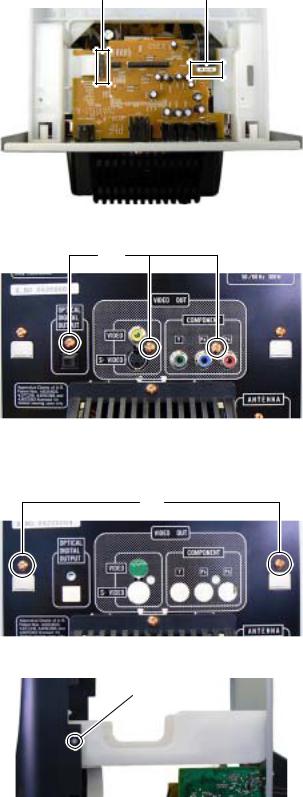
3.1.3 Removing the VIDEO BOARD assembly (See Fig.7, 8)
(1)Disconnect the card wire from MAIN BOARD assembly connected to connector CN920 of the VIDEO BOARD assembly. (See Fig.7)
(2)Disconnect the card wire from SURROUND AMP BOARD assembly connected to connector CN931 of the VIDEO BOARD assembly. (See Fig.7)
(3)Remove the three screws D attaching the VIDEO BOARD assembly. (See Fig.8)
3.1.4Removing the MECHA CHASSIS (See Fig.9, 10)
(1)Remove the two screws E attaching the MECHA CHASSIS. (See Fig.9)
(2)Remove the two screws F attaching the both side of MECHA CHASSIS (See Fig.10)
CN920 |
CN931 |
Fig.7
D
Fig.8
E
Fig.9
F
Fig.10
1-10 (No.MB616<Rev.002>)
3.1.5 Removing the REAR COVER with FAN (See Fig.11, 12)
(1)Remove the One screw G attaching the REAR COVER. (See Fig.11)
(2)Disengage six hooks a engaged REAR COVER. (See Fig.11)
(3)Disconnect the connector wire from FAN connected to connector CN304 of the SURROUND AMP BOARD assembly. (See Fig.12)
G
hook |
hook |
a |
a |
Fig.11
CN304 |
Fig.12
(No.MB616<Rev.002>)1-11
Loading...