

Operation and Safety Manual
Original Instructions - Keep this manual with the machine at all times.
Boom Lift Models
680S
S/N 0300189341 to Present
3121678
July 4, 2014


FOREWORD
FOREWORD
This manual is a very important tool! Keep it with the machine at all times.
The purpose of this manual is to provide owners, users, operators, lessors, and lessees with the precautions and operating
procedures essential for the safe and proper machine operation for its intended purpose.
Due to continuous product improvements, JLG Industries, Inc. reserves the right to make specification changes without
prior notification. Contact JLG Industries, Inc. for updated information.
3121678 – JLG Lift – a
FOREWORD
SAFETY ALERT SYMBOLS AND SAFETY SIGNAL WORDS
This is the Safety Alert Symbol. It is used to alert you to the potential personal injury
hazards. Obey all safety messages that follow this symbol to avoid possible injury or
death
INDICATES AN IMMINENTLY HAZARDOUS SITUATION. IF NOT AVOIDED, WILL
RESULT IN SERIOUS INJURY OR DEATH. THIS DECAL WILL HAVE A RED BACKGROUND.
INDICATES A POTENTIALLY HAZARDOUS SITUATION. IF NOT AVOIDED, COULD
RESULT IN SERIOUS INJURY OR DEATH. THIS DECAL WILL HAVE AN ORANGE BACKGROUND.
INDICATES A POTENTIALLY HAZARDOUS SITUATION. IF NOT AVOIDED, MAY RESULT
IN MINOR OR MODERATE INJURY. IT MAY ALSO ALERT AGAINST UNSAFE PRACTICES.
THIS DECAL WILL HAVE A YELLOW BACKGROUND.
INDICATES INFORMATION OR A COMPANY POLICY THAT RELATES DIRECTLY OR INDIRECTLY TO THE SAFETY OF PERSONNEL OR PROTECTION OF PROPERTY.
b – JLG Lift – 3121678

THIS PRODUCT MUST COMPLY WITH ALL SAFETY RELATED BULLETINS. CONTACT JLG
INDUSTRIES, INC. OR THE LOCAL AUTHORIZED JLG REPRESENTATIVE FOR INFORMATION REGARDING SAFETY-RELATED BULLETINS WHICH MAY HAVE BEEN ISSUED FOR
THIS PRODUCT.
JLG INDUSTRIES, INC. SENDS SAFETY RELATED BULLETINS TO THE OWNER OF
RECORD OF THIS MACHINE. CONTACT JLG INDUSTRIES, INC. TO ENSURE THAT THE
CURRENT OWNER RECORDS ARE UPDATED AND ACCURATE.
JLG INDUSTRIES, INC. MUST BE NOTIFIED IMMEDIATELY IN ALL INSTANCES WHERE
JLG PRODUCTS HAVE BEEN INVOLVED IN AN ACCIDENT INVOLVING BODILY INJURY
OR DEATH OF PERSONNEL OR WHEN SUBSTANTIAL DAMAGE HAS OCCURRED TO PERSONAL PROPERTY OR THE JLG PRODUCT.
For:
• Accident Reporting
• Product Safety Publications
• Current Owner Updates
• Questions Regarding
Product Safety
Contact:
Product Safety and Reliability Department
JLG Industries, Inc.
13224 Fountainhead Plaza
Hagerstown, MD 21742
USA
or Your Local JLG Office
(See addresses on inside of manual cover)
In USA:
Toll Free: 877-JLG-SAFE (877-554-7233)
Outside USA:
Phone: 240-420-2661
Fax: 301-745-3713
E-mail: ProductSafety@JLG.com
FOREWORD
• Standards and Regulations
Compliance Information
• Questions Regarding Special
Product Applications
• Questions Regarding Product Modifications
3121678 – JLG Lift – c

FOREWORD
REVISION LOG
Original Issue - July 4, 2014
d – JLG Lift – 3121678

TABLE OF CONTENTS
SECTION - PARAGRAPH, SUBJECT PAGE SECTION - PARAGRAPH, SUBJECT PAGE
SECTION - 1 - SAFETY PRECAUTIONS
1.1 GENERAL . . . . . . . . . . . . . . . . . . . . . . . . . . . . . . . . . . . . . . . . . . . . 1-1
1.2 PRE-OPERATION . . . . . . . . . . . . . . . . . . . . . . . . . . . . . . . . . . . . . 1-1
Operator Training and Knowledge . . . . . . . . . . . . . . . . . 1-1
Workplace Inspection. . . . . . . . . . . . . . . . . . . . . . . . . . . . . . 1-2
Machine Inspection. . . . . . . . . . . . . . . . . . . . . . . . . . . . . . . . 1-3
1.3 OPERATION. . . . . . . . . . . . . . . . . . . . . . . . . . . . . . . . . . . . . . . . . . 1-3
General . . . . . . . . . . . . . . . . . . . . . . . . . . . . . . . . . . . . . . . . . . . 1-3
Trip and Fall Hazards. . . . . . . . . . . . . . . . . . . . . . . . . . . . . . . 1-4
Electrocution Hazards . . . . . . . . . . . . . . . . . . . . . . . . . . . . . 1-5
Tipping Hazards . . . . . . . . . . . . . . . . . . . . . . . . . . . . . . . . . . . 1-7
Crushing and Collision Hazards . . . . . . . . . . . . . . . . . . 1-10
1.4 TOWING, LIFTING, AND HAULING. . . . . . . . . . . . . . . . . . . . 1-11
1.5 MAINTENANCE. . . . . . . . . . . . . . . . . . . . . . . . . . . . . . . . . . . . . .1-11
Maintenance Hazards. . . . . . . . . . . . . . . . . . . . . . . . . . . . 1-11
Battery Hazards. . . . . . . . . . . . . . . . . . . . . . . . . . . . . . . . . . 1-13
SECTION - 2 - USER RESPONSIBILITIES, MACHINE PREPARATION,
AND INSPECTION
2.1 PERSONNEL TRAINING . . . . . . . . . . . . . . . . . . . . . . . . . . . . . . . 2-1
Operator Training . . . . . . . . . . . . . . . . . . . . . . . . . . . . . . . . . 2-1
Training Supervision . . . . . . . . . . . . . . . . . . . . . . . . . . . . . . . 2-1
Operator Responsibility . . . . . . . . . . . . . . . . . . . . . . . . . . . . 2-1
2.2 PREPARATION, INSPECTION, AND MAINTENANCE . . . . . 2-2
Pre-Start Inspection. . . . . . . . . . . . . . . . . . . . . . . . . . . . . . . . 2-4
Function Check. . . . . . . . . . . . . . . . . . . . . . . . . . . . . . . . . . . . 2-5
2.3 HORIZONTAL AND CAPACITY LIMIT SWITCHES . . . . . . . 2-10
2.4 OSCILLATING AXLE LOCKOUT TEST (IF EQUIPPED). . . . 2-14
SECTION - 3 - MACHINE CONTROLS AND INDICATORS
3.1 GENERAL . . . . . . . . . . . . . . . . . . . . . . . . . . . . . . . . . . . . . . . . . . . . 3-1
3.2 CONTROLS AND INDICATORS . . . . . . . . . . . . . . . . . . . . . . . . 3-1
SECTION - 4 - MACHINE OPERATION
4.1 DESCRIPTION . . . . . . . . . . . . . . . . . . . . . . . . . . . . . . . . . . . . . . . . 4-1
4.2 OPERATING CHARACTERISTICS AND LIMITATIONS . . . . 4-1
4.3 ENGINE OPERATION. . . . . . . . . . . . . . . . . . . . . . . . . . . . . . . . . . 4-2
4.4 TRAVELING (DRIVING) . . . . . . . . . . . . . . . . . . . . . . . . . . . . . . . . 4-6
4.5 STEERING . . . . . . . . . . . . . . . . . . . . . . . . . . . . . . . . . . . . . . . . . . . . 4-7
4.6 PLATFORM . . . . . . . . . . . . . . . . . . . . . . . . . . . . . . . . . . . . . . . . . . 4-9
General . . . . . . . . . . . . . . . . . . . . . . . . . . . . . . . . . . . . . . . . . . . 2-9
Ground Control Console . . . . . . . . . . . . . . . . . . . . . . . . . . . 3-2
Ground Control Indicator Panel . . . . . . . . . . . . . . . . . . . . 3-7
Platform Console . . . . . . . . . . . . . . . . . . . . . . . . . . . . . . . . . . 3-9
Platform Control Indicator Panel . . . . . . . . . . . . . . . . . 3-15
Capacities . . . . . . . . . . . . . . . . . . . . . . . . . . . . . . . . . . . . . . . . . 4-1
Stability . . . . . . . . . . . . . . . . . . . . . . . . . . . . . . . . . . . . . . . . . . . 4-1
Starting Procedure . . . . . . . . . . . . . . . . . . . . . . . . . . . . . . . . 4-2
Shutdown Procedure . . . . . . . . . . . . . . . . . . . . . . . . . . . . . . 4-3
Fuel Reserve / Shut-Off System. . . . . . . . . . . . . . . . . . . . . 4-3
Traveling Forward and Reverse . . . . . . . . . . . . . . . . . . . . 4-7
Platform Level Adjustment. . . . . . . . . . . . . . . . . . . . . . . . . 4-9
3121678 – JLG Lift – i

TABLE OF CONTENTS
SECTION - PARAGRAPH, SUBJECT PAGE SECTION - PARAGRAPH, SUBJECT PAGE
Platform Rotation . . . . . . . . . . . . . . . . . . . . . . . . . . . . . . . . . 4-9
4.7 BOOM . . . . . . . . . . . . . . . . . . . . . . . . . . . . . . . . . . . . . . . . . . . . . . . 4-9
Swinging the Boom . . . . . . . . . . . . . . . . . . . . . . . . . . . . . . 4-10
Raising and Lowering the Boom . . . . . . . . . . . . . . . . . . 4-10
Telescoping the Main Boom . . . . . . . . . . . . . . . . . . . . . . 4-10
4.8 FUNCTION SPEED CONTROL . . . . . . . . . . . . . . . . . . . . . . . . 4-10
4.9 OSCILLATING AXLE LOCKOUT TEST (IF EQUIPPED) . . . 4-10
4.10 EMERGENCY TOWING . . . . . . . . . . . . . . . . . . . . . . . . . . . . . . . 4-11
4.11 TOW BAR (IF EQUIPPED). . . . . . . . . . . . . . . . . . . . . . . . . . . . . 4-12
4.12 SHUT DOWN AND PARK. . . . . . . . . . . . . . . . . . . . . . . . . . . . . 4-14
4.13 LIFTING AND TIE DOWN . . . . . . . . . . . . . . . . . . . . . . . . . . . . . 4-14
Lifting. . . . . . . . . . . . . . . . . . . . . . . . . . . . . . . . . . . . . . . . . . . . 4-14
Tie Down. . . . . . . . . . . . . . . . . . . . . . . . . . . . . . . . . . . . . . . . . 4-15
SECTION - 5 - EMERGENCY PROCEDURES
5.1 GENERAL . . . . . . . . . . . . . . . . . . . . . . . . . . . . . . . . . . . . . . . . . . . . 5-1
5.2 INCIDENT NOTIFICATION. . . . . . . . . . . . . . . . . . . . . . . . . . . . . 5-1
5.3 EMERGENCY OPERATION. . . . . . . . . . . . . . . . . . . . . . . . . . . . . 5-1
Operator Unable to Control Machine. . . . . . . . . . . . . . . 5-1
Platform or Boom Caught Overhead . . . . . . . . . . . . . . . 5-2
Boom Movement Prevented By Boom Control
System . . . . . . . . . . . . . . . . . . . . . . . . . . . . . . . . . . . . . . . . . . 5-2
5.4 EMERGENCY TOWING PROCEDURES. . . . . . . . . . . . . . . . . . 5-2
NANCE
6.1 INTRODUCTION. . . . . . . . . . . . . . . . . . . . . . . . . . . . . . . . . . . . . . 6-1
6.2 OPERATING SPECIFICATIONS. . . . . . . . . . . . . . . . . . . . . . . . . 6-1
Specifications and Performance Data . . . . . . . . . . . . . . 6-2
Capacities. . . . . . . . . . . . . . . . . . . . . . . . . . . . . . . . . . . . . . . . . 6-3
Engine Data . . . . . . . . . . . . . . . . . . . . . . . . . . . . . . . . . . . . . . 6-3
Battery. . . . . . . . . . . . . . . . . . . . . . . . . . . . . . . . . . . . . . . . . . . . 6-5
Tires . . . . . . . . . . . . . . . . . . . . . . . . . . . . . . . . . . . . . . . . . . . . . . 6-5
Major Component Weights . . . . . . . . . . . . . . . . . . . . . . . . 6-6
Hydraulic Oil . . . . . . . . . . . . . . . . . . . . . . . . . . . . . . . . . . . . . . 6-6
6.3 SERIAL NUMBER LOCATION . . . . . . . . . . . . . . . . . . . . . . . . . . 6-9
6.4 MAINTENANCE AND LUBRICATION . . . . . . . . . . . . . . . . . . 6-15
6.5 TIRES & WHEELS . . . . . . . . . . . . . . . . . . . . . . . . . . . . . . . . . . . . 6-24
Tire Inflation . . . . . . . . . . . . . . . . . . . . . . . . . . . . . . . . . . . . . 6-24
Tire Damage . . . . . . . . . . . . . . . . . . . . . . . . . . . . . . . . . . . . . 6-24
Tire Replacement. . . . . . . . . . . . . . . . . . . . . . . . . . . . . . . . . 6-25
Wheel Replacement . . . . . . . . . . . . . . . . . . . . . . . . . . . . . . 6-26
Wheel Installation . . . . . . . . . . . . . . . . . . . . . . . . . . . . . . . . 6-26
6.6 PROPANE FUEL FILTER REPLACEMENT. . . . . . . . . . . . . . . 6-28
Removal . . . . . . . . . . . . . . . . . . . . . . . . . . . . . . . . . . . . . . . . . 6-28
Installation . . . . . . . . . . . . . . . . . . . . . . . . . . . . . . . . . . . . . . . 6-28
6.7 PROPANE FUEL SYSTEM PRESSURE RELIEF . . . . . . . . . . . 6-29
6.8 SUPPLEMENTAL INFORMATION . . . . . . . . . . . . . . . . . . . . . 6-30
SECTION - 6 - GENERAL SPECIFICATIONS & OPERATOR MAINTE-
SECTION - 7 - INSPECTION AND REPAIR LOG
ii – JLG Lift – 3121678

LIST OF FIGURES
FIGURE NUMBER - TITLE PAGE FIGURE NUMBER - TITLE PAGE
2-1. Basic Nomenclature - Sheet 1 of 2 . . . . . . . . . . . . . . . . . . . . 2-6
2-2. Basic Nomenclature - Sheet 2 of 2 . . . . . . . . . . . . . . . . . . . . 2-7
2-3. Daily Walk-Around Inspection - Sheet 1 of 2 . . . . . . . . . . 2-8
2-4. Daily Walk-Around Inspection - Sheet 2 of 2 . . . . . . . . . . 2-9
2-5. Horizontal and Capacity Limit Switches - Sheet 1 of 2 2-10
2-6. Horizontal and Capacity Limit Switches - Sheet 2 of 2 2-11
2-7. Limiting and Cut-Out Switches - Sheet 1 of 2. . . . . . . . . 2-12
2-8. Limiting and Cut-Out Switches - Sheet 2 of 2. . . . . . . . . 2-13
3-1. Ground Control Console . . . . . . . . . . . . . . . . . . . . . . . . . . . . . 3-3
3-1. Ground Control Indicator Panel . . . . . . . . . . . . . . . . . . . . . . 3-8
3-2. Platform Console . . . . . . . . . . . . . . . . . . . . . . . . . . . . . . . . . . .3-11
3-3. Platform Control Indicator Panel. . . . . . . . . . . . . . . . . . . . . 3-17
3-4. Fuel Level Indicator . . . . . . . . . . . . . . . . . . . . . . . . . . . . . . . . . 3-18
4-1. Position of Least Backward Stability . . . . . . . . . . . . . . . . . . 4-4
4-2. Position of Least Forward Stability . . . . . . . . . . . . . . . . . . . . 4-5
4-3. Grade and Side Slopes . . . . . . . . . . . . . . . . . . . . . . . . . . . . . . . 4-8
4-4. Drive Disconnect Hub. . . . . . . . . . . . . . . . . . . . . . . . . . . . . . .4-11
4-5. Lifting and Tie Down Chart . . . . . . . . . . . . . . . . . . . . . . . . . . 4-16
4-6. Decal Location - Sheet 1 of 5 . . . . . . . . . . . . . . . . . . . . . . . .4-17
4-7. Decal Location - Sheet 2 of 5 . . . . . . . . . . . . . . . . . . . . . . . .4-18
4-8. Decal Location - Sheet 3 of 5 . . . . . . . . . . . . . . . . . . . . . . . .4-19
4-9. Decal Location - Sheet 4 of 5 . . . . . . . . . . . . . . . . . . . . . . . .4-20
4-10. Decal Location - Sheet 5 of 5 . . . . . . . . . . . . . . . . . . . . . . . .4-21
6-1. Serial Number Locations . . . . . . . . . . . . . . . . . . . . . . . . . . . . . 6-9
6-2. Engine Operating Temperature Specifications - Deutz -
Sheet 1 of 2 . . . . . . . . . . . . . . . . . . . . . . . . . . . . . . . . . . . . . .6-10
6-3. Engine Operating Temperature Specifications - Deutz -
Sheet 2 of 2 . . . . . . . . . . . . . . . . . . . . . . . . . . . . . . . . . . . . . . 6-11
6-4. Engine Operating Temperature Specifications - GM - Sheet
1 of 2. . . . . . . . . . . . . . . . . . . . . . . . . . . . . . . . . . . . . . . . . . . . . 6-12
6-5. Engine Operating Temperature Specifications - GM - Sheet
2 of 2. . . . . . . . . . . . . . . . . . . . . . . . . . . . . . . . . . . . . . . . . . . . . 6-13
6-6. Maintenance and Lubrication Diagram . . . . . . . . . . . . . . 6-14
6-7. Deutz 2011 Engine Dipstick . . . . . . . . . . . . . . . . . . . . . . . . . 6-20
6-8. Filter Lock Assembly . . . . . . . . . . . . . . . . . . . . . . . . . . . . . . . . 6-29
3121678 – JLG Lift – iii

LIST OF FIGURES
FIGURE NUMBER - TITLE PAGE FIGURE NUMBER - TITLE PAGE
This Page Left Blank Intentionally.
iv – JLG Lift – 3121678

LIST OF TABLES
TABLE NUMBER - TITLE PAGE TABLE NUMBER - TITLE PAGE
1-1 Minimum Approach Distances (M.A.D.) . . . . . . . . . . . . . . . 1-6
1-2 Beaufort Scale (For Reference Only). . . . . . . . . . . . . . . . . . . 1-9
2-1 Inspection and Maintenance Table . . . . . . . . . . . . . . . . . . . 2-3
4-1 Decal Location Legend . . . . . . . . . . . . . . . . . . . . . . . . . . . . . .4-22
6-1 Operating Specifications . . . . . . . . . . . . . . . . . . . . . . . . . . . . . 6-1
6-2 Specifications and Performance Data . . . . . . . . . . . . . . . . . 6-2
6-3 Capacities . . . . . . . . . . . . . . . . . . . . . . . . . . . . . . . . . . . . . . . . . . . 6-3
6-4 Deutz D2011L04 Specifications . . . . . . . . . . . . . . . . . . . . . . . 6-3
6-5 Deutz TD 2.9 Specifications. . . . . . . . . . . . . . . . . . . . . . . . . . . 6-4
6-6 GM 3.0L. . . . . . . . . . . . . . . . . . . . . . . . . . . . . . . . . . . . . . . . . . . . . . 6-4
6-7 Battery Specifications . . . . . . . . . . . . . . . . . . . . . . . . . . . . . . . . 6-5
6-8 Tire Specifications. . . . . . . . . . . . . . . . . . . . . . . . . . . . . . . . . . . . 6-5
6-9 Component Weights . . . . . . . . . . . . . . . . . . . . . . . . . . . . . . . . . 6-6
6-10 Hydraulic Oil . . . . . . . . . . . . . . . . . . . . . . . . . . . . . . . . . . . . . . . . . 6-6
6-11 Mobilfluid 424 Specs . . . . . . . . . . . . . . . . . . . . . . . . . . . . . . . . .6-7
6-12 UCon Hydrolube HP-5046 . . . . . . . . . . . . . . . . . . . . . . . . . . . . 6-7
6-13 Mobil DTE 13M Specs . . . . . . . . . . . . . . . . . . . . . . . . . . . . . . . . 6-8
6-14 Mobil EAL 224H Specs. . . . . . . . . . . . . . . . . . . . . . . . . . . . . . . . 6-8
6-15 Exxon Univis HVI 26 Specs . . . . . . . . . . . . . . . . . . . . . . . . . . . . 6-9
6-16 Lubrication Specifications . . . . . . . . . . . . . . . . . . . . . . . . . . .6-15
6-17 Wheel Torque Chart. . . . . . . . . . . . . . . . . . . . . . . . . . . . . . . . .6-27
7-1 Inspection and Repair Log. . . . . . . . . . . . . . . . . . . . . . . . . . . . 7-1
3121678 – JLG Lift – v

LIST OF TABLES
TABLE NUMBER - TITLE PAGE TABLE NUMBER - TITLE PAGE
This Page Left Blank Intentionally.
vi – JLG Lift – 3121678

1.1 GENERAL
SECTION 1 - SAFETY PRECAUTIONS
SECTION 1. SAFETY PRECAUTIONS
This section outlines the necessary precautions for proper and
safe machine usage and maintenance. It is mandatory that a daily
routine is established based on the content of this manual to promote proper machine usage. A maintenance program, using the
information provided in this manual and the Service and Maintenance Manual, must also be established by a qualified person and
must be followed to ensure that the machine is safe to operate.
The owner/user/operator/lessor/lessee of the machine must not
accept operating responsibility until this manual has been read,
training is accomplished, and operation of the machine has been
completed under the supervision of an experienced and qualified operator.
This section contains the responsibilities of the owner, user, operator, lessor, and lessee concerning safety, training, inspection,
maintenance, application, and operation. If there are any questions with regard to safety, training, inspection, maintenance,
application, and operation, please contact JLG Industries, Inc.
(“JLG”).
FAILURE TO COMPLY WITH THE SAFETY PRECAUTIONS LISTED IN THIS MANUAL
COULD RESULT IN MACHINE DAMAGE, PROPERTY DAMAGE, PERSONAL INJURY OR
DEATH.
1.2 PRE-OPERATION
Operator Training and Knowledge
• The Operation and Safety Manual must be read and under-
stood in its entirety before operating the machine. For clarification, questions, or additional information regarding any
portions of this manual, contact JLG Industries, Inc.
3121678 – JLG Lift – 1-1

SECTION 1 - SAFETY PRECAUTIONS
• An operator must not accept operating responsibilities until
adequate training has been given by competent and authorized persons.
• Allow only those authorized and qualified personnel to operate the machine who have demonstrated that they understand the safe and proper operation and maintenance of the
unit.
• Read, understand, and obey all DANGERS, WARNINGS, CAUTIONS, and operating instructions on the machine and in this
manual.
• Ensure that the machine is to be used in a manner which is
within the scope of its intended application as determined by
JLG.
• All operating personnel must be familiar with the emergency
controls and emergency operation of the machine as specified
in this manual.
• Read, understand, and obey all applicable employer, local, and
governmental regulations as they pertain to your utilization
and application of the machine.
Workplace Inspection
• Precautions to avoid all hazards in the work area must be
taken by the user before and during operation of the machine.
• Do not operate or raise the platform from a position on trucks,
trailers, railway cars, floating vessels, scaffolds or other equipment unless the application is approved in writing by JLG.
• Before operation, check work area for overhead hazards such
as electric lines, bridge cranes, and other potential overhead
obstructions.
• Check operating surfaces for holes, bumps, drop-offs, obstructions, debris, concealed holes, and other potential hazards.
• Check the work area for hazardous locations. Do not operate
the machine in hazardous environments unless approved for
that purpose by JLG.
• Ensure that the ground conditions are adequate to support
the maximum tire load indicated on the tire load decals
located on the chassis adjacent to each wheel. Do not travel
on unsupported surfaces.
1-2 – JLG Lift – 3121678

SECTION 1 - SAFETY PRECAUTIONS
Machine Inspection
• Do not operate this machine until the inspections and functional checks as specified in Section 2 of this manual have
been performed.
• Do not operate this machine until it has been serviced and
maintained according to the maintenance and inspection
requirements as specified in the machine’s Service and Maintenance Manual.
• Ensure all safety devices are operating properly. Modification
of these devices is a safety violation.
MODIFICATION OR ALTERATION OF AN AERIAL WORK PLATFORM SHALL BE MADE
ONLY WITH PRIOR WRITTEN PERMISSION FROM THE MANUFACTURER.
• Do not operate any machine on which the safety or instruction
placards or decals are missing or illegible.
• Check the machine for modifications to original components.
Ensure that any modifications have been approved by JLG.
• Avoid accumulation of debris on platform floor. Keep mud, oil,
grease, and other slippery substances from footwear and platform floor.
1.3 OPERATION
General
• Machine operation requires your full attention. Bring the
machine to a full stop before using any device, i.e. cell phones,
two-way radios, etc. that will distract your attention from
safely operating the machine.
• Do not use the machine for any purpose other than positioning personnel, their tools, and equipment.
• Before operation, the user must be familiar with the machine
capabilities and operating characteristics of all functions.
• Never operate a malfunctioning machine. If a malfunction
occurs, shut down the machine. Remove the unit from service
and notify the proper authorities.
• Do not remove, modify, or disable any safety devices.
• Never slam a control switch or lever through neutral to an
opposite direction. Always return switch to neutral and stop
before moving the switch to the next function. Operate controls with slow and even pressure.
• Do not allow personnel to tamper with or operate the
machine from the ground with personnel in the platform,
except in an emergency.
3121678 – JLG Lift – 1-3
SECTION 1 - SAFETY PRECAUTIONS
• Do not carry materials directly on platform railing unless
approved by JLG.
• When two or more persons are in the platform, the operator
shall be responsible for all machine operations.
• Always ensure that power tools are properly stowed and never
left hanging by their cord from the platform work area.
• When driving, always position boom over rear axle in line with
the direction of travel. Remember, if boom is over the front
axle, steer and drive functions will be reversed.
• Do not assist a stuck or disabled machine by pushing or pulling except by pulling at the chassis tie-down lugs.
• Fully lower platform and shut off all power before leaving
machine.
• Remove all rings, watches, and jewelry when operating
machine. Do not wear loose fitting clothing or long hair unrestrained which may become caught or entangled in equipment.
• Persons under the influence of drugs or alcohol or who are
subject to seizures, dizziness or loss of physical control must
not operate this machine.
Trip and Fall Hazards
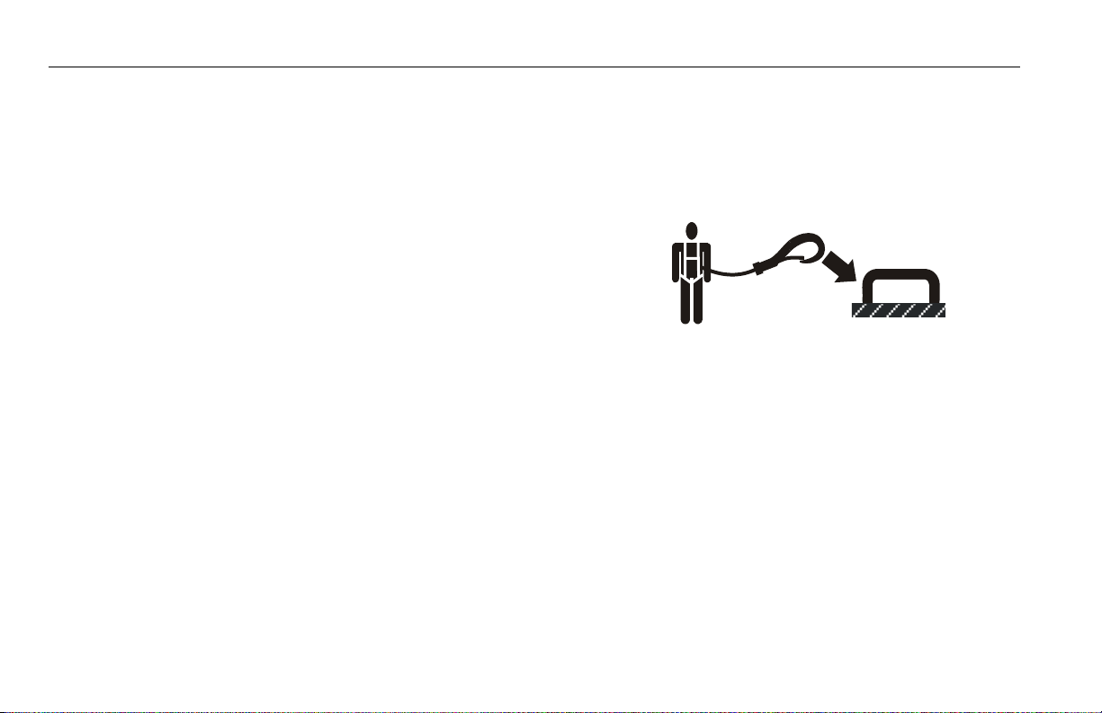
• During operation, occupants in the platform must wear a full
body harness with a lanyard attached to an authorized lanyard
anchorage point. Attach only one (1) lanyard per lanyard
anchorage point..
• Enter and exit only through gate area. Use extreme caution
when entering or leaving platform. Ensure that the platform
assembly is fully lowered. Face the machine when entering or
leaving the platform. Always maintain “three point contact”
with the machine, using two hands and one foot or two feet
and one hand at all times during entry and exit.
1-4 – JLG Lift – 3121678
SECTION 1 - SAFETY PRECAUTIONS
• Before operating the machine, make sure all gates are closed
and fastened in their proper position.
• Keep both feet firmly positioned on the platform floor at all
times. Never position ladders, boxes, steps, planks, or similar
items on unit to provide additional reach for any purpose.
• Keep oil, mud, and slippery substances cleaned from footwear
and the platform floor.
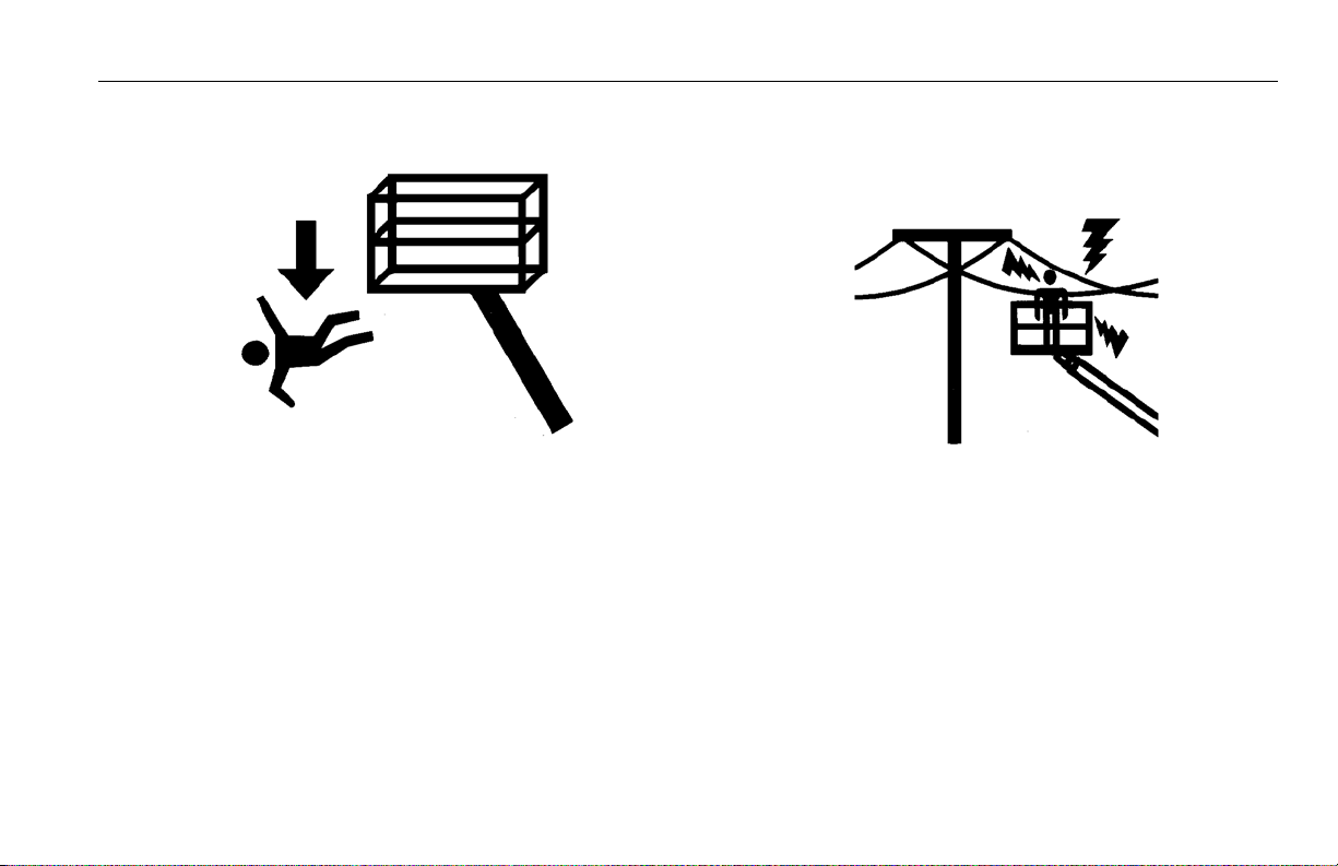
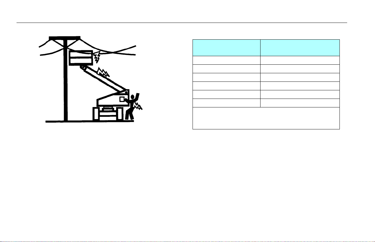
Electrocution Hazards
• This machine is not insulated and does not provide protection
from contact or proximity to electrical current.
3121678 – JLG Lift – 1-5
SECTION 1 - SAFETY PRECAUTIONS
Table 1-1. Minimum Approach Distances (M.A.D.)
• Maintain distance from electrical lines, apparatus, or any energized (exposed or insulated) parts according to the Minimum
Approach Distance (MAD) as shown in Table 1-1.
• Allow for machine movement and electrical line swaying.
Voltage Range
(Phase to Phase)
0 to 50 KV 10 (3)
Over 50KV to 200 KV 15 (5)
Over 200 KV to 350 KV 20 (6)
Over 350 KV to 500 KV 25 (8)
Over 500 KV to 750 KV 35 (11)
Over 750 KV to 1000 KV 45 (14)
NOTE: This requirement shall apply except where
employer, local or governmental regulations are
more stringent.
• Maintain a clearance of at least 10 ft. (3m) between any part of
the machine and its occupants, their tools, and their equipment from any electrical line or apparatus carrying up to
50,000 volts. One foot additional clearance is required for
every additional 30,000 volts or less.
MINIMUM APPROACH DISTANCE
in Feet (Meters)
1-6 – JLG Lift – 3121678
SECTION 1 - SAFETY PRECAUTIONS
• The minimum approach distance may be reduced if insulating
barriers are installed to prevent contact, and the barriers are
rated for the voltage of the line being guarded. These barriers
shall not be part of (or attached to) the machine. The minimum approach distance shall be reduced to a distance within
the designed working dimensions of the insulating barrier.
This determination shall be made by a qualified person in
accordance with the employer, local, or governmental requirements for work practices near energized equipment
DO NOT MANEUVER MACHINE OR PERSONNEL INSIDE PROHIBITED ZONE (MAD).
ASSUME ALL ELECTRICAL PARTS AND WIRING ARE ENERGIZED UNLESS KNOWN OTHERWISE.
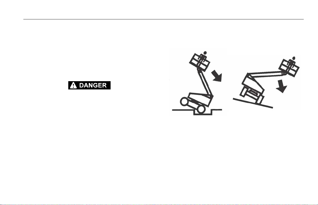
Tipping Hazards
• The user must be familiar with the surface before driving. Do
not exceed the allowable sideslope and grade while driving.
• Do not elevate platform or drive with platform elevated while
on or near a sloping, uneven, or soft surface. Ensure machine is
positioned on a firm, level and smooth surface before elevating platform or driving with the platform in the elevated position.
• Before driving on floors, bridges, trucks, and other surfaces,
check allowable capacity of the surfaces.
3121678 – JLG Lift – 1-7

SECTION 1 - SAFETY PRECAUTIONS
• Never exceed the maximum work load as specified on the
platform. Keep all loads within the confines of the platform,
unless authorized by JLG.
• Keep the chassis of the machine a minimum of 2 ft. (0.6m)
from holes, bumps, drop-offs, obstructions, debris, concealed
holes, and other potential hazards at the ground level.
• Do not push or pull any object with the boom.
• Never attempt to use the machine as a crane. Do not tie-off
machine to any adjacent structure. Never attach wire, cable, or
any similar items to platform.
• Do not operate the machine when wind conditions exceed 28
mph (12.5 m/s). Refer to Table 1-2, Beaufort Scale (For Reference Only).
• Do not increase the surface area of the platform or the load.
Increase of the area exposed to the wind will decrease stability.
• Do not increase the platform size with unauthorized deck
extensions or attachments.
• If boom assembly or platform is in a position that one or more
wheels are off the ground, all persons must be removed before
attempting to stabilize the machine. Use cranes, forklift trucks,
or other appropriate equipment to stabilize machine.
1-8 – JLG Lift – 3121678
DO NOT OPERATE THE MACHINE WHEN WIND CONDITIONS EXCEED 28 MPH (12.5 M/
S).
Table 1-2. Beaufort Scale (For Reference Only)
SECTION 1 - SAFETY PRECAUTIONS
Beaufort
Number
0 0 0-0.2 Calm Calm. Smoke rises vertically
1 1-3 0.3-1.5 Light air Wind motion visible in smoke
2 4-7 1.6-3.3 Light breeze Wind felt on exposed skin. Leaves rustle
3 8-12 3.4-5.4 Gentle breeze Leaves and smaller twigs in constant motion
4 13-18 5.5-7.9 Moderate breeze Dust and loose paper raised. Small branches begin to move.
5 19-24 8.0-10.7 Fresh breeze Smaller trees sway.
6 25-31 10.8-13.8 Strong breeze Large branches in motion. Flags waving near horizontal. Umbrella use
7 32-38 13.9-17.1 Near Gale/Moderate Gale Whole trees in motion. Effort needed to walk against the wind.
8 39-46 17.2-20.7 Fresh Gale Twigs broken fro m trees. Cars veer on road.
9 47-54 20.8-24.4 Strong Gale Light structure damage.
Wind Speed
mph m/s
Description Land Conditions
becomes difficult.
3121678 – JLG Lift – 1-9
SECTION 1 - SAFETY PRECAUTIONS
Crushing and Collision Hazards
• Approved head gear must be worn by all operating and
ground personnel.
• Check work area for clearances overhead, on sides, and bottom of platform when lifting or lowering platform, and driving.
• During operation, keep all body parts inside platform railing.
• Use the boom functions, not the drive function, to position the
platform close to obstacles.
• Always post a lookout when driving in areas where vision is
obstructed.
• Keep non-operating personnel at least 6 ft. (1.8m) away from
machine during all driving and swing operations.
• Under all travel conditions, the operator must limit travel
speed according to conditions of ground surface, congestion,
visibility, slope, location of personnel, and other factors which
may cause collision or injury to personnel.
• Be aware of stopping distances in all drive speeds. When driving in high speed, switch to low speed before stopping. Travel
grades in low speed only.
• Do not use high speed drive in restricted or close quarters or
when driving in reverse.
• Exercise extreme caution at all times to prevent obstacles from
striking or interfering with operating controls and persons in
the platform.
• Be sure that operators of other overhead and floor level
machines are aware of the aerial work platform’s presence. Disconnect power to overhead cranes.
• Warn personnel not to work, stand, or walk under a raised
boom or platform. Position barricades on floor if necessary.
1-10 – JLG Lift – 3121678

SECTION 1 - SAFETY PRECAUTIONS
1.4 TOWING, LIFTING, AND HAULING
• Never allow personnel in platform while towing, lifting, or
hauling.
• This machine should not be towed, except in the event of
emergency, malfunction, power failure, or loading/unloading.
Refer to the Emergency Procedures section of this manual for
emergency towing procedures.
• Ensure boom is in the stowed position and the turntable
locked prior to towing, lifting or hauling. The platform must be
completely empty of tools.
• When lifting machine, lift only at designated areas of the
machine. Lift the unit with equipment of adequate capacity.
• Refer to the Machine Operation section of this manual for lifting information.
1.5 MAINTENANCE
This sub-section contains general safety precautions which must
be observed during maintenance of this machine. Additional precautions to be observed during machine maintenance are
inserted at the appropriate points in this manual and in the Service and Maintenance Manual. It is of utmost importance that
maintenance personnel pay strict attention to these precautions
to avoid possible injury to personnel or damage to the machine
or property. A maintenance program must be established by a
qualified person and must be followed to ensure that the
machine is safe.
Maintenance Hazards
• Shut off power to all controls and ensure that all moving parts
are secured from inadvertent motion prior to performing any
adjustments or repairs.
• Never work under an elevated platform until it has been fully
lowered to the full down position, if possible, or otherwise
supported and restrained from movement with appropriate
safety props, blocking, or overhead supports.
• DO NOT attempt to repair or tighten any hydraulic hoses or fittings while the machine is powered on or when the hydraulic
system is under pressure.
• Always relieve hydraulic pressure from all hydraulic circuits
before loosening or removing hydraulic components.
3121678 – JLG Lift – 1-11
SECTION 1 - SAFETY PRECAUTIONS
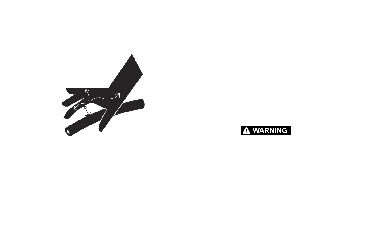
• DO NOT use your hand to check for leaks. Use a piece of cardboard or paper to search for leaks. Wear gloves to help protect
hands from spraying fluid.
• Ensure replacement parts or components are identical or
equivalent to original parts or components.
• Never attempt to move heavy parts without the aid of a
mechanical device. Do not allow heavy objects to rest in an
unstable position. Ensure adequate support is provided when
raising components of the machine.
• Do not use machine as a ground for welding.
• When performing welding or metal cutting operations, precautions must be taken to protect the chassis from direct
exposure to weld and metal cutting spatter.
• Do not refuel the machine with the engine running.
• Use only approved non-flammable cleaning solvents.
• Do not replace items critical to stability, such as batteries or
solid tires, with items of different weight or specification. Do
not modify unit in any way to affect stability.
• Refer to the Service and Maintenance Manual for the weights
of critical stability items.
MODIFICATION OR ALTERATION OF AN AERIAL WORK PLATFORM SHALL BE MADE
ONLY WITH PRIOR WRITTEN PERMISSION FROM THE MANUFACTURER.
1-12 – JLG Lift – 3121678

Battery Hazards
SECTION 1 - SAFETY PRECAUTIONS
• Always disconnect batteries when servicing electrical components or when performing welding on the machine.
• Do not allow smoking, open flame, or sparks near battery during charging or servicing.
• Do not contact tools or other metal objects across the battery
terminals.
• Always wear hand, eye, and face protection when servicing
batteries. Ensure that battery acid does not come in contact
with skin or clothing.
BATTERY FLUID IS HIGHLY CORROSIVE. AVOID CONTACT WITH SKIN AND
CLOTHING AT ALL TIMES. IMMEDIATELY RINSE ANY CONTACTED AREA WITH
CLEAN WATER AND SEEK MEDICAL ATTENTION.
• Charge batteries only in a well ventilated area.
• Avoid overfilling the battery fluid level. Add distilled water to
batteries only after the batteries are fully charged.
3121678 – JLG Lift – 1-13

SECTION 1 - SAFETY PRECAUTIONS
NOTES:
1-14 – JLG Lift – 3121678

SECTION 2 - USER RESPONSIBILITIES, MACHINE PREPARATION, AND INSPECTION
SECTION 2. USER RESPONSIBILITIES, MACHINE PREPARATION, AND INSPECTION
2.1 PERSONNEL TRAINING
The aerial platform is a personnel handling device; so it is necessary that it be operated and maintained only by trained personnel.
Persons under the influence of drugs or alcohol or who are subject to seizures, dizziness or loss of physical control must not
operate this machine.
Operator Training
Operator training must cover:
1. Use and limitations of the controls in the platform and at the
ground, emergency controls and safety systems.
2. Control labels, instructions, and warnings on the machine.
3. Rules of the employer and government regulations.
4. Use of approved fall protection device.
5. Enough knowledge of the mechanical operation of the
machine to recognize a malfunction or potential malfunction.
6. The safest means to operate the machine where overhead
obstructions, other moving equipment, and obstacles,
depressions, holes, dropoffs.
7. Means to avoid the hazards of unprotected electrical conductors.
8. Specific job requirements or machine application.
Training Supervision
Training must be done under the supervision of a qualified person in an open area free of obstructions until the trainee has
developed the ability to safely control and operate the machine.
Operator Responsibility
The operator must be instructed that he/she has the responsibility and authority to shut down the machine in case of a malfunction or other unsafe condition of either the machine or the job
site.
3121678 – JLG Lift – 2-1

SECTION 2 - USER RESPONSIBILITIES, MACHINE PREPARATION, AND INSPECTION
2.2 PREPARATION, INSPECTION, AND MAINTENANCE
The following table covers the periodic machine inspections and
maintenance required by JLG Industries, Inc. Consult local regulations for further requirements for aerial work platforms. The frequency of inspections and maintenance must be increased as
necessary when the machine is used in a harsh or hostile environment, if the machine is used with increased frequency, or if the
machine is used in a severe manner.
JLG INDUSTRIES, INC. RECOGNIZES A FACTORY-TRAINED SERVICE TECHNICIAN AS A
PERSON WHO HAS SUCCESSFULLY COMPLETED THE JLG SERVICE TRAINING SCHOOL
FOR THE SPECIFIC JLG PRODUCT MODEL.
2-2 – JLG Lift – 3121678

SECTION 2 - USER RESPONSIBILITIES, MACHINE PREPARATION, AND INSPECTION
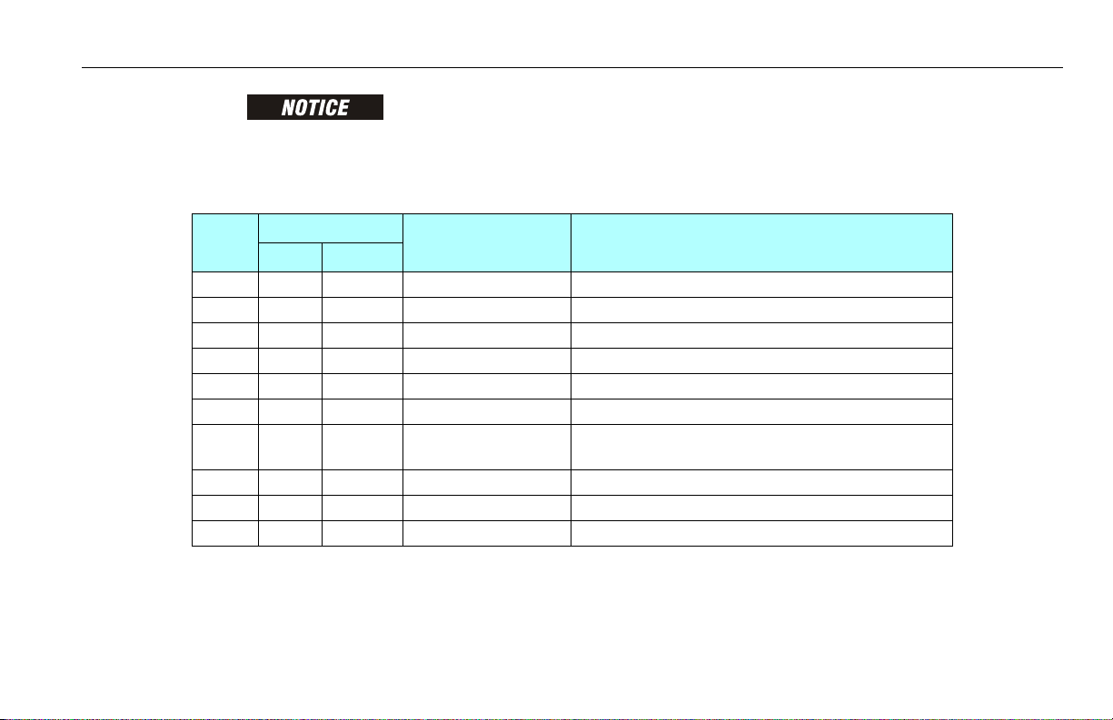
Table 2-1. Inspection and Maintenance Table
Type Frequenc y
Pre-Start Inspection Before using each day; or
whenever there’s an Operator change.
Pre-Delivery Inspection (S ee Note) Before each sal e, lease, or rental delivery. Owner, Dealer, or User Qualif ied JLG Mechanic Service and Maintenance Manual
Frequent Inspection
(See Note)
Annual Machine Inspection
(See Note)
Preventative Maintenance At intervals as specified in the S ervice and Maintenance
NOTE: Inspection forms are available from JLG. Use the Service and Maintenance Manual to perform inspections.
In service for 3 months or 150 hours, whichever comes first;
o r
Out of service for a perio d of more than 3 months;
o r
Purchase d used.
An n ua l ly , n o la t er t ha n 13 m on t hs f ro m th e da te o f p r i or
inspection.
Manual.
Primary
Responsibility
User or Operator User or Operator Operator and Safety Manual
Owner, Dealer, or User Q ualified JLG Mechanic Ser vice and Maintenance Manual
Owner, Dealer, or User Factory Trained
Owner, Dealer, or User Q ualified JLG Mechanic Ser vice and Maintenance Manual
Service
Qualification
Service Technician
(Recommended)
Reference
and applicable JLG inspection form
and applicable JLG inspection form
Service and Maintenance Manual
and applicable JLG inspection form
3121678 – JLG Lift – 2-3
SECTION 2 - USER RESPONSIBILITIES, MACHINE PREPARATION, AND INSPECTION
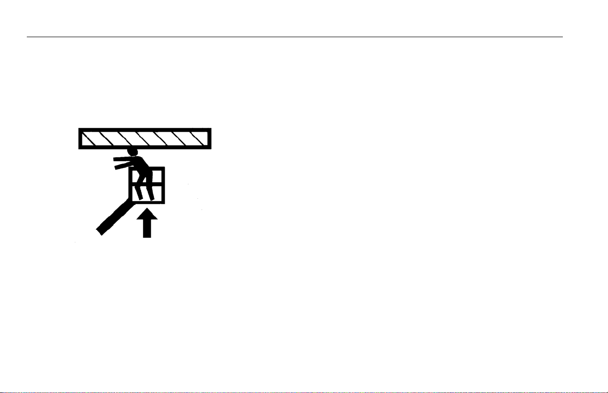
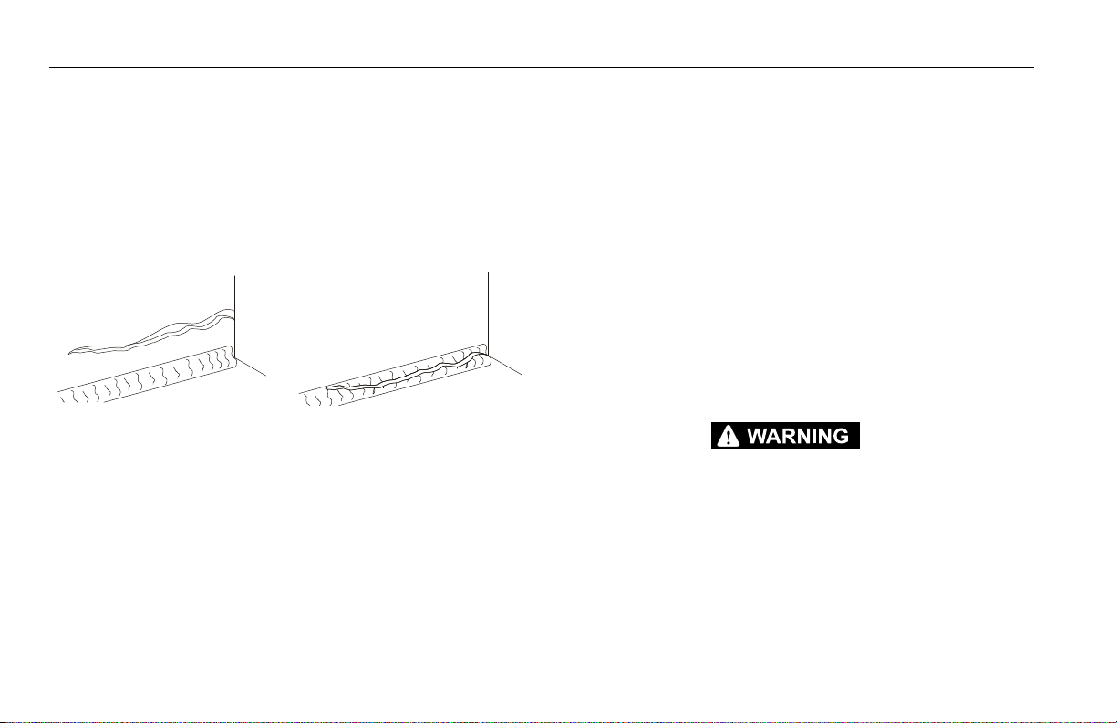
Parent Metal Crack Weld Crack
Pre-Start Inspection
The Pre-Start Inspection should include each of the following:
1. Cleanliness – Check all surfaces for leakage (oil, fuel, or battery fluid) or foreign objects. Report any leakage to the
proper maintenance personnel.
2. Structure - Inspect the machine structure for dents, damage, weld or parent metal cracks or other discrepancies.
3. Decals and Placards – Check all for cleanliness and legibility. Make sure none of the decals and placards are missing.
Make sure all illegible decals and placards are cleaned or
replaced.
4. Operators and Safety Manuals – Make sure a copy of the
Operator and Safety Manual, EMI Safety Manual (Domestic
only), and ANSI Manual of Responsibilities (Domestic only) is
enclosed in the weather resistant storage container.
5. “Walk-Around” Inspection – Refer to Figure 2-3. and Figure
2-4.
6. Battery – Charge as required.
7. Fuel (Combustion Engine Powered Machines) – Add the
proper fuel as necessary.
8. Engine Oil Supply - Ensure the engine oil level is at the Full
mark on the dipstick and the filler cap is secure.
9. Hydraulic Oil – Check the hydraulic oil level. Ensure hydraulic oil is added as required.
10. Function Check – Once the “Walk-Around” Inspection is
complete, perform a functional check of all systems in an
area free of overhead and ground level obstructions. Refer to
Section 4 for more specific instructions.
IF THE MACHINE DOES NOT OPERATE PROPERLY, TURN OFF THE MACHINE IMMEDIATELY! REPORT THE PROBLEM TO THE PROPER MAINTENANCE PERSONNEL. DO NOT
OPERATE THE MACHINE UNTIL IT IS DECLARED SAFE FOR OPERATION.
2-4 – JLG Lift – 3121678

SECTION 2 - USER RESPONSIBILITIES, MACHINE PREPARATION, AND INSPECTION
Function Check
Perform the Function Check as follows:
1. From the ground control console with no load in the platform:
a. Check that all guards protecting the switches or locks
are in place;
b. Operate all functions and check all limiting and cut-out
switches;
c. Check auxiliary power (or manual descent);
d. Ensure that all machine functions are disabled when
the Emergency Stop Button is activated.
2. From the platform control console:
a. Ensure that the control console is firmly secured in the
proper location;
b. Check that all guards protecting the switches or locks
are in place;
c. Operate all functions and check all limiting and cut-out
switches;
d. Ensure that all machine functions are disabled when
the Emergency Stop Button is pushed in.
3. With the platform in the transport (stowed) position:
a. Drive the machine on a grade, not to exceed the rated
gradeability, and stop to ensure the brakes hold;
b. Check the tilt sensor alarm to ensure proper operation.
3121678 – JLG Lift – 2-5

SECTION 2 - USER RESPONSIBILITIES, MACHINE PREPARATION, AND INSPECTION
108
7
13
14
12
11
6
5
3
4
1
2
6
5
3
4
1
2
9
10
8
7
13
14
12
Figure 2-1. Basic Nomenclature - Sheet 1 of 2
2-6 – JLG Lift – 3121678

SECTION 2 - USER RESPONSIBILITIES, MACHINE PREPARATION, AND INSPECTION
1. Steer Wheels
2. Drive Wheels
3. Lift Cylinder
4. Tower
5. Level Link
6. Upright
7. Base Boom S ection
8. Mid Boom Section
9. Fly Boom Se ction
10. Boom Assembly
11. Power Track
12. Jib (If Equipped)
13. Platform
14. Platform Console
Figure 2-2. Basic Nomenclature - Sheet 2 of 2
3121678 – JLG Lift – 2-7

SECTION 2 - USER RESPONSIBILITIES, MACHINE PREPARATION, AND INSPECTION
9
9
9
1
2
12
14
3
4
5
6
7
8
10
2
6
11
5
9
9
5
11
6
3
12
7
13
6
5
Figure 2-3. Daily Walk-Around Inspection - Sheet 1 of 2
2-8 – JLG Lift – 3121678

SECTION 2 - USER RESPONSIBILITIES, MACHINE PREPARATION, AND INSPECTION
General
Begin the "Walk-Around Inspection" at Item 1, as noted on the diagram. Continue to the right (counterclockwise viewed from top)
checking each item in sequence for the conditions listed in the following checklist.
TO AVOID POSSIBLE INJURY, BE SURE MACHINE POWER IS OFF.
DO NOT OPERATE MACHINE UNTIL ALL MALFUNCTIONS HAVE BEEN CORRECTED.
INSPECTION NOTE: On all components, make sure there are no loose
or missing parts, that they are securely fastened, and no visible damage, leaks or excessive wear exists in addition to any other criteria mentioned.
1. Platform Assembly and Gate - Footswitch works properly,
not modified, disabled or blocked. Latch, stop, and hinges in
working condition.
2. Platform & Ground Control Consoles - Switches and levers
return to neutral, decals/placards secure and legible, control
markings legible.
3. Boom Sections/Uprights/Turntable - See Inspection Note.
4. Swing Drive - No evidence of damage.
5. Wheel/Tire Assemblies - No loose or missing lug nuts,
proper inflation (pneumatic). Inspect for worn tread, cuts,
tears or other discrepancies. Inspect wheels for damage and
corrosion.
6. Drive Motor, Brake, and Hub - No evidence of leakage.
7. Hood Assemblies - See Inspection Note.
8. Auxiliary Hydraulic Pump - See Inspection Note.
9. All Hydraulic Cylinders - No visible damage; pivot pins and
hydraulic hoses undamaged, not leaking.
10. Turntable Bearing - Evidence of proper lubrication. No evi-
dence of loose bolts or looseness between bearing and
machine.
11. Tie Rod Ends and Steering Spindles - See Inspection Note.
12. Horizontal and Capacity Limit Switches - Switches oper-
ate properly.
13. Main Hydraulic Pump - See Inspection Note.
14. Platform Rotator - See Inspection Note.
Figure 2-4. Daily Walk-Around Inspection - Sheet 2 of 2
3121678 – JLG Lift – 2-9

SECTION 2 - USER RESPONSIBILITIES, MACHINE PREPARATION, AND INSPECTION
Figure 2-5. Horizontal and Capacity Limit Switches - Sheet 1 of 2
2.3 HORIZONTAL AND CAPACITY LIMIT SWITCHES
2-10 – JLG Lift – 3121678

SECTION 2 - USER RESPONSIBILITIES, MACHINE PREPARATION, AND INSPECTION
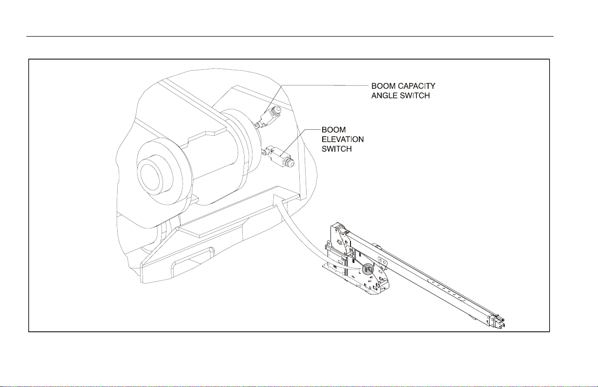
Figure 2-6. Horizontal and Capacity Limit Switches - Sheet 2 of 2
Item Description Operation Characteristic
1Boom Capacity
Length Switch
Activates platform capacity light to indicate the platform capacity at a designated boom length.
2 Boom Extension
Switch
Reduces drive speed when boom reaches a designated length.
3Boom Capacity
Angle Switch
Activates platform capacity light to indicate the platform capacity at a designated boom height.
4 Boom Elevation
Switch
Reduces drive speed when boom is raised above horizontal.
3121678 – JLG Lift – 2-11
SECTION 2 - USER RESPONSIBILITIES, MACHINE PREPARATION, AND INSPECTION
Figure 2-7. Limiting and Cut-Out Switches - Sheet 1 of 2
2-12 – JLG Lift – 3121678

SECTION 2 - USER RESPONSIBILITIES, MACHINE PREPARATION, AND INSPECTION
Figure 2-8. Limiting and Cut-Out Switches - Sheet 2 of 2
3121678 – JLG Lift – 2-13

SECTION 2 - USER RESPONSIBILITIES, MACHINE PREPARATION, AND INSPECTION
2.4 OSCILLATING AXLE LOCKOUT TEST (IF EQUIPPED)
LOCKOUT SYSTEM TEST MUST BE PERFORMED QUARTERLY, ANY TIME A SYSTEM COMPONENT IS REPLACED, OR WHEN IMPROPER SYSTEM OPERATION IS SUSPECTED.
NOTE: Ensure boom is fully retracted, lowered, and centered between
drive wheels prior to beginning lockout cylinder test.
1. Place a 6 inches (15.2 cm) high block with ascension ramp in
front of left front wheel.
2. From platform control console, start engine
3. Place the Drive control lever to the forward position and
carefully drive machine up ascension ramp until left front
wheel is on top of block.
4. Carefully activate Swing control lever and position boom
over right side of machine.
5. With boom over right side of machine, place Drive control
lever to Reverse and drive machine off of block and ramp.
6. Have an assistant check to see that left front or right rear
wheel remains elevated in position off of ground.
7. Carefully activate Swing control lever and return boom to
stowed position (centered between drive wheels). When
boom reaches center, stowed position, lockout cylinders
should release and allow wheel to rest on ground, it may be
necessary to activate Drive to release cylinders.
2-14 – JLG Lift – 3121678

SECTION 2 - USER RESPONSIBILITIES, MACHINE PREPARATION, AND INSPECTION
8. Place the 6 inches (15.2 cm) high block with ascension ramp
in front of right front wheel.
9. Place Drive control lever to Forward and carefully drive
machine up ascension ramp until right front wheel is on top
of block.
10. With boom over left side of machine, place Drive control
lever to Reverse and drive machine off of block and ramp.
11. Have an assistant check to see that right front or left rear
wheel remains elevated in position off of ground.
12. Carefully activate Swing control lever and return boom to
stowed position (centered between drive wheels). When
boom reaches center, stowed position, lockout cylinders
should release and allow wheel to rest on ground, it may be
necessary activate Drive to release cylinders.
13. If lockout cylinders do not function properly, have qualified
personnel correct the malfunction prior to any further operation.
3121678 – JLG Lift – 2-15

SECTION 2 - USER RESPONSIBILITIES, MACHINE PREPARATION, AND INSPECTION
NOTES:
2-16 – JLG Lift – 3121678

SECTION 3 - MACHINE CONTROLS AND INDICATORS
SECTION 3. MACHINE CONTROLS AND INDICATORS
3.1 GENERAL
THE MANUFACTURER HAS NO DIRECT CONTROL OVER MACHINE APPLICATION AND
OPERATION. THE USER AND OPERATOR ARE RESPONSIBLE FOR CONFORMING WITH
GOOD SAFETY PRACTICES.
This section provides the necessary information needed to
understand control functions.
3.2 CONTROLS AND INDICATORS
NOTE: All machines are equipped with control consoles that use sym-
bols to indicate control functions. On ANSI machines refer to
decal located on the control box guard in front of the control box
or by the ground controls for these symbols and the corresponding functions.
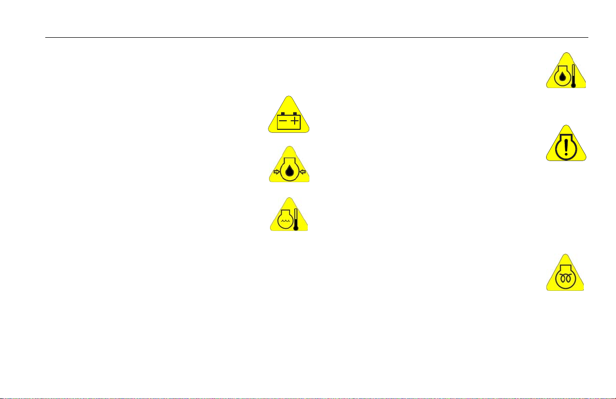
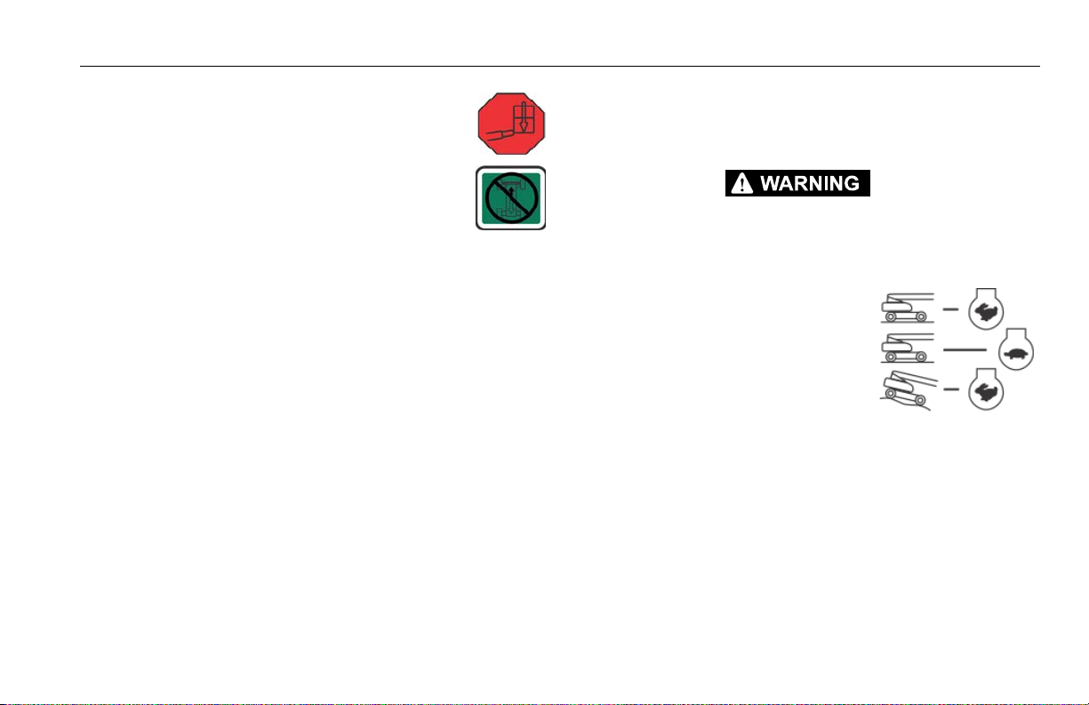
NOTE: The indicator panels use different shaped symbols to alert the
operator to different types of operational situations that could
arise. The meaning of those symbols are explained below.
Indicates a potentially hazardous situation, which if
not corrected, could result in serious injury or death.
This indicator will be red.
Indicates an abnormal operating condition, which if
not corrected, may result in machine interruption or
damage. This indicator will be yellow.
Indicates important information regarding the operating condition, i.e. procedures essential for safe operation. This indicator will be green with the exception of
the capacity indicator which will be green or yellow
depending upon platform position.
3121678 – JLG Lift – 3-1

SECTION 3 - MACHINE CONTROLS AND INDICATORS
1. Indicator Panel.
TO AVOID SERIOUS INJURY, DO NOT OPERATE MACHINE IF ANY CONTROL LEVERS OR
TOGGLE SWITCHES CONTROLLING PLATFORM MOVEMENT DO NOT RETURN TO THE
OFF POSITION WHEN RELEASED.
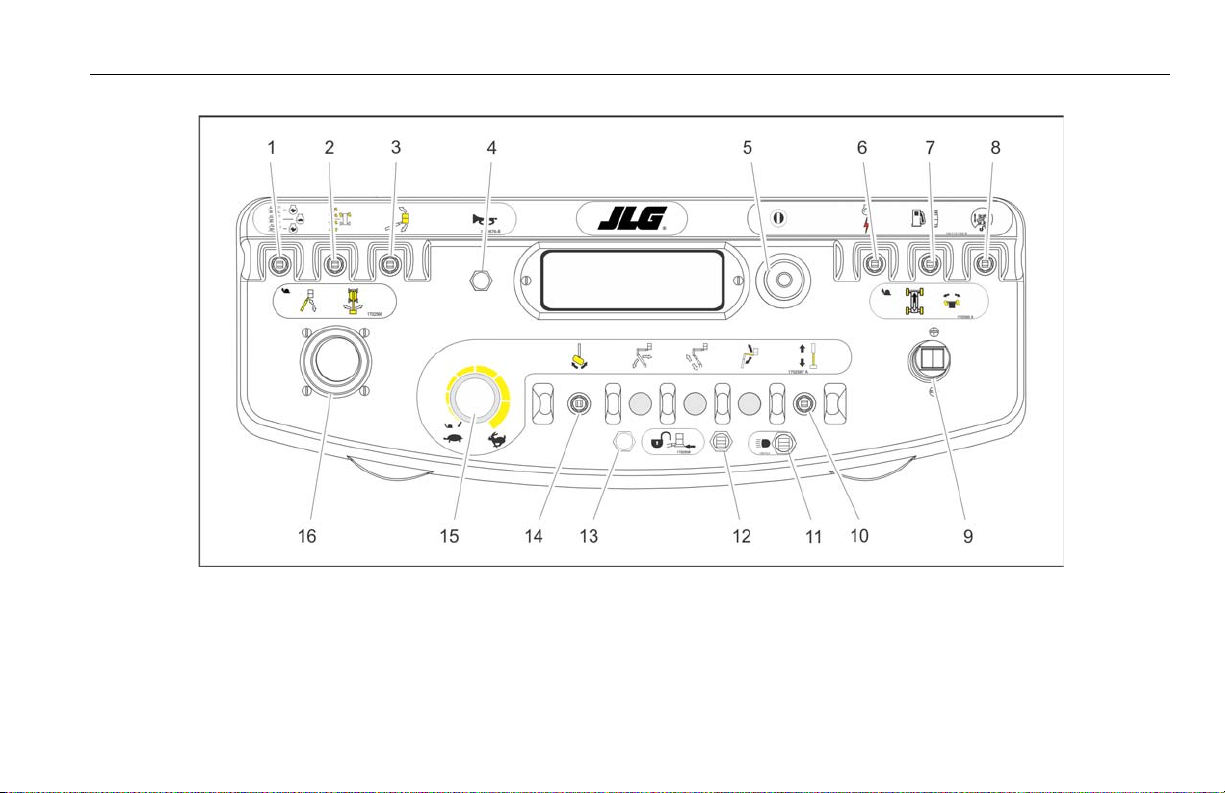
Ground Control Console
(See Figure 3-1., Ground Control Console).
NOTE: When Power/Emergency Stop switch is in the “ON” position and
engine is not running, an alarm will sound, indicating Ignition is
“ON”.
WHEN THE MACHINE IS SHUT DOWN THE MASTER/EMERGENCY STOP SWITCH MUST
BE POSITIONED TO THE “OFF” POSITION TO PREVENT DRAINING THE BATTERY.
NOTE: The Function Enable switch must be held down in
order to operate Telescope, Swing, Lift, Jib Lift,
Platform Level Override, and Platform Rotate
functions.
The LED Indicator Panel contains indicator lights that signal
problem conditions or functions operating during machine
operation.
TO AVOID SERIOUS INJURY, DO NOT OPERATE MACHINE IF ANY CONTROL LEVERS OR
TOGGLE SWITCHES CONTROLLING PLATFORM MOVEMENT DO NOT RETURN TO THE
OFF POSITION WHEN RELEASED.
2. Telescope Control
Provides extension and retraction of
the boom.
3-2 – JLG Lift – 3121678

1. Indicator Panel
2. Telescope
3. Swing
4. Lift
5. Platform/Ground Select Switch
6. Hourmeter
7. Power/Emergency Stop
8. Engine Start/Auxiliary Power/Function Enable
9. Platform Leveling Override
10. Platform Rotate
Figure 3-1. Ground Control Console
SECTION 3 - MACHINE CONTROLS AND INDICATORS
3121678 – JLG Lift – 3-3

SECTION 3 - MACHINE CONTROLS AND INDICATORS
3. Swing Control
Provides 360 degrees continuous
turntable rotation.
4. Lift Control
Provides raising and lowering of the
boom.
NOTE: When the Platform/Ground Select Switch is in the
center position, power is shut off to the controls at
both operating consoles. Remove the key to prevent the controls from being actuated. The key is
removable in the platform position on CE specification machines. The key must be available to
ground personnel in the event of an emergency.
5. Platform/Ground Select Switch
The three position, key operated switch supplies power to the platform control console
when positioned to Platform. With the switch
key turned to the Ground position only
ground controls are operable.
3-4 – JLG Lift – 3121678

SECTION 3 - MACHINE CONTROLS AND INDICATORS
6. Hourmeter
Registers the amount of time the
machine has been in use, with engine
running. By connecting into the oil
pressure circuit of the engine, only engine run hours are
recorded. The hourmeter registers up to 9,999.9 hours and
cannot be reset.
NOTE: When Power/Emergency Stop switch is in the “On” position and
engine is not running, an alarm will sound, indicating Ignition is
“On”.
WHEN THE MACHINE IS SHUT DOWN THE MASTER/EMERGENCY STOP SWITCH MUST
BE POSITIONED TO THE “OFF” POSITION TO PREVENT DRAINING THE BATTERY.
NOTE: On machines with diesel engines, when Glow Plug Indicator is
lighted (Yellow), wait until light goes out before cranking engine.
7. Power/Emergency Stop Switch
A two-position red mushroom shaped switch
supplies power to Platform/Ground Select
switch when pulled out (on). When pushed in
(off), power is shut off to the Platform/Ground Select switch.
8. Engine Start/ Auxiliary Power Switch /Function Enable.
To start the engine, the switch must be held "Up"
until the engine starts.
To use auxiliary power, the switch must be held
“Down” for duration of auxiliary pump use. Aux
power can only be used if the engine is not running.
The enable switch must be held "Down" to enable
all boom controls when the engine is running.
NOTE: Auxiliary power only works if there is no engine oil
pressure, and is disabled if engine is running.
NOTE: Functions will operate at a slower than normal rate because of
the lesser flow of hydraulic fluid delivered.
WHEN USING AUXILIARY POWER, DO NOT OPERATE MORE THAN ONE FUNCTION AT A
TIME. (SIMULTANEOUS OPERATION CAN OVERLOAD THE AUXILIARY PUMP.)
3121678 – JLG Lift – 3-5

SECTION 3 - MACHINE CONTROLS AND INDICATORS
10. Platform Rotate
ONLY USE THE PLATFORM LEVELING OVERRIDE FUNCTION FOR SLIGHT LEVELING OF
THE PLATFORM. INCORRECT USE COULD CAUSE THE LOAD/OCCUPANT TO SHIFT OR
FALL. FAILURE TO DO SO COULD RESULT IN DEATH OR SERIOUS INJURY.
9. Platform Leveling Override
A three position switch allows the
operator to adjust the automatic self
leveling system. This switch is used to
adjust platform level in situations
such as ascending/descending a
grade.
Provides rotation of the platform.
3-6 – JLG Lift – 3121678
SECTION 3 - MACHINE CONTROLS AND INDICATORS
Ground Control Indicator Panel
(See Figure 3-1., Ground Control Indicator Panel.)
1. No Alternator Output Indicator
Indicates a problem in the charging circuit,
and service is required.
2. Engine Oil Pressure Indicator
Indicates that engine oil pressure is below normal and service is required.
3. High Engine Coolant Temperature Indicator
(Liquid Cooled Engines)
Indicates that engine coolant temperature is
abnormally high and service is required.
4. Engine Oil Temperature Indicator (Deutz, If
Equipped)
Indicates that the temperature of the engine
oil, which also serves as engine coolant, is
abnormally high and service is required.
5. Malfunction Indicator
Indicates that the JLG Control System has
detected a malfunction and a Diagnostic Trouble Code has been set. Refer to the Service
Manual for instructions concerning the trouble codes and
trouble code retrieval.
The malfunction indicator light will illuminate for 2-3 seconds when the key is positioned to the on position to act as
a self test.
6. Glow Plug/ Wait to Start Indicator
Indicates the glow plugs are on. The glow
plugs are automatically turned on with the
ignition circuit and remain on for approximately seven seconds. Start the engine only after the light
goes out.
3121678 – JLG Lift – 3-7

SECTION 3 - MACHINE CONTROLS AND INDICATORS
1. No Alternato r Output
2. Engine Oil Pressure
3. Engine Water Temp.
4. Engine Oil Temp.
5. Malfunction Indicator
6. Glow Plug/Wait to Star t
7. Platform Overload
8. Drive and Steer Disable
Figure 3-1. Ground Control Indicator Panel
3-8 – JLG Lift – 3121678
SECTION 3 - MACHINE CONTROLS AND INDICATORS
7. Platform Overload Indicator. (If Equipped)
Indicates the platform has been overloaded.
8. Drive and Steer Disable Indicator (If equipped)
Indicates the Drive and Steer Disable function
has been activated.
Platform Console
(See Figure 3-2., Platform Console)
TO AVOID SERIOUS INJURY, DO NOT OPERATE MACHINE IF ANY CONTROL LEVERS OR
TOGGLE SWITCHES CONTROLLING PLATFORM MOVEMENT DO NOT RETURN TO THE
OFF OR NEUTRAL POSITION WHEN RELEASED.
1. Drive Speed/Torque Select
The machine has a two position
switch - The forward position
gives maximum drive speed. The
back position gives maximum
torque for rough terrain and
climbing grades.
3121678 – JLG Lift – 3-9

SECTION 3 - MACHINE CONTROLS AND INDICATORS
2. Steer Select (If Equipped)
When equipped with four wheel steering, the
action of the steering system is operator
selectable. The center switch position gives
conventional front wheel steering with the rear wheels unaffected. This is for normal driving at maximum speeds. The
forward position is for “crab” steering. When in this mode
both front and rear axles steer in the same direction, which
allows the chassis to move sideways as it goes forward. This
can be used for positioning the machine in aisle ways or
against buildings. The back switch position is for “coordinated” steering. In this mode the front and rear axles steer in
the opposite directions to produce the tightest turning circle
for maneuvering in confined areas.
To re-synchronize the front and rear axles, position the rear
drive wheels to the forward drive position by selecting
either crab or compound steer, then select front steer (center switch position) to operate the normal steering function.
ONLY USE THE PLATFORM LEVELING OVERRIDE FUNCTION FOR SLIGHT LEVELING OF
THE PLATFORM. INCORRECT USE COULD CAUSE THE LOAD/OCCUPANTS TO SHIFT OR
FALL. FAILURE TO DO SO COULD RESULT IN DEATH OR SERIOUS INJURY.
3. Platform Leveling Override
A three position switch allows the operator to
adjust the automatic self leveling system. This
switch is used to adjust platform level in situations such as ascending/descending a grade.
4. Horn
A push-type Horn switch supplies electrical
power to an audible warning device when pressed.
5. Power/Emergency Stop Switch
A two-position red mushroom shaped switch
furnishes power to Platform Controls when
pulled out (on). When pushed in (off), power is
shut off to the platform functions.
3-10 – JLG Lift – 3121678
SECTION 3 - MACHINE CONTROLS AND INDICATORS
1. Drive Speed / Torque Select
2. Steer Select
3. Platform Level Override
4. Horn
5. Power/Emergency Stop
6. Engine Start / Aux Power
7. Fuel Select
8. Drive Orientation Override
9. Drive/Steer
10. Telescope
11. Lights
12. Soft Touch Override
13. Soft Touch Indicator
14. Platform Rotate
15. Function Speed Control
16. Main Lift / Swing
Figure 3-2. Platform Console
3121678 – JLG Lift – 3-11
SECTION 3 - MACHINE CONTROLS AND INDICATORS
6. Engine Start/Auxiliary Power
When pushed forward, the switch energizes
the starter motor to start the engine.
The Auxiliary Power control switch energizes
the electrically operated hydraulic pump.
(Switch must be held on for duration of auxiliary pump use.)
The auxiliary pump functions to provide sufficient oil flow to
operate the basic machine functions should the main pump
or engine fail. The auxiliary pump will operate boom lift,
telescope and swing.
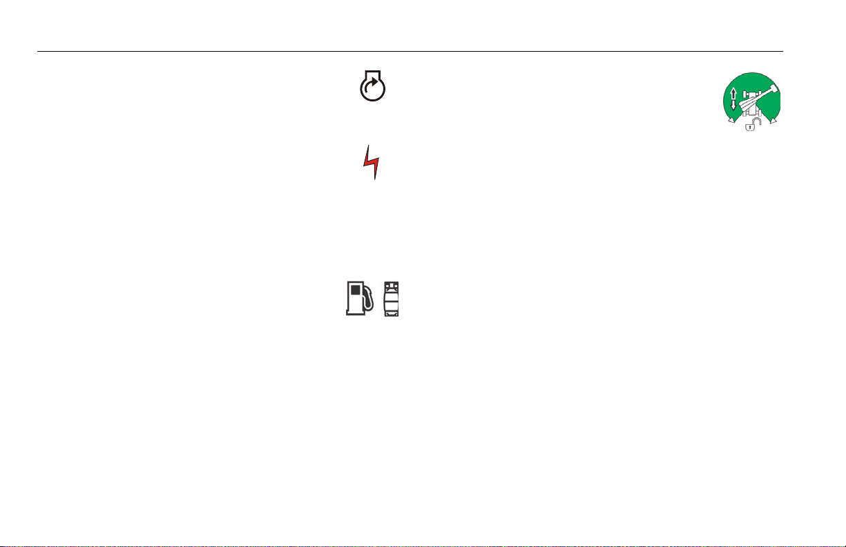
7. Fuel Select (Dual Fuel Engine Only) (If
Equipped)
Gasoline or liquid propane fuel may be
selected by moving the switch to the appropriate position. It
is unnecessary to purge the fuel system before switching
fuels, so there is no waiting period when switching fuels
while the engine is running.
8. Drive Orientation Override
When the boom is swung over the rear tires or
further in either direction, the Drive Orientation indicator will illuminate when the drive
function is selected. Push and release the switch, and within
3 seconds move the Drive/Steer control to activate drive or
steer. Before driving, locate the black/white orientation
arrows on both the chassis and the platform controls. Move
the drive controls in a direction matching the directional
arrows for the intended direction of travel.
3-12 – JLG Lift – 3121678

SECTION 3 - MACHINE CONTROLS AND INDICATORS
NOTE: Lift, Swing, and Drive control levers are spring-loaded and will
automatically return to neutral (off ) position when released.
TO AVOID SERIOUS INJURY, DO NOT OPERATE MACHINE IF ANY CONTROL LEVERS OR
TOGGLE SWITCHES CONTROLLING PLATFORM MOVEMENT DO NOT RETURN TO THE
OFF OR NEUTRAL POSITION WHEN RELEASED.
NOTE: To operate the Drive joystick, pull up on the lock-
ing ring below the handle.
NOTE: The Drive joystick is spring loaded and will automatically return
to neutral (off) position when released.
9. Drive/Steer
Push forward to drive forward,
pull back to drive in reverse.
Steering is accomplished via a
thumb-activated rocker switch on
the end of the steer handle.
10. Main Boom Telescope
Provides extension and retraction of the main
boom.
11. Lights (If Equipped)
This switch operates accessory lights if the
machine is so equipped. The ignition switch
does not have to be on to operate the lights, so care must be
taken to avoid draining the battery if left unattended. The
master switch and / or the ignition switch at the ground control will turn off power to all lights.
12. Soft Touch Override Switch (If equipped)
This switch enables the functions that
were cut out by the Soft Touch system to
operate again at creep speed, allowing the operator to move
the platform away from the obstacle that caused the shutdown situation.
13. Soft Touch Indicator (If Equipped)
Indicates the Soft Touch bumper is against
an object. All controls are cut out until the
override button is pushed, at which time controls are active
in the Creep Mode.
3121678 – JLG Lift – 3-13

SECTION 3 - MACHINE CONTROLS AND INDICATORS
14. Platform Rotate
Provides rotation of the platform when positioned to the right or left.
NOTE: MAIN LIFT, SWING, and DRIVE control levers are spring-loaded
and will automatically return to neutral (OFF) position when
released.
15. Function Speed Control
This control affects the speed of telescope
and platform rotate. Turning the knob all
the way counterclockwise until it clicks puts
drive, main lift and swing into creep mode.
NOTE: To operate the Main Boom Lift/Swing joystick,
pull up on the locking ring below the handle.
NOTE: The Main Boom Lift/Swing joystick is spring
loaded and will automatically return to neutral
(off) position when released.
16. Main Lift/Swing Controller
Provides main lift and swing. Push
forward to lift up, pull backward
to boom down. Move right to
swing right, move left to swing
left. Moving the joystick activates
switches to provide the functions
selected.
NOTE: Main boom lift and swing functions may be selected in combi-
nation. Maximum speed is reduced when multiple functions are
selected.
3-14 – JLG Lift – 3121678
SECTION 3 - MACHINE CONTROLS AND INDICATORS
Platform Control Indicator Panel
(See Figure 3-3., Platform Control Indicator Panel)
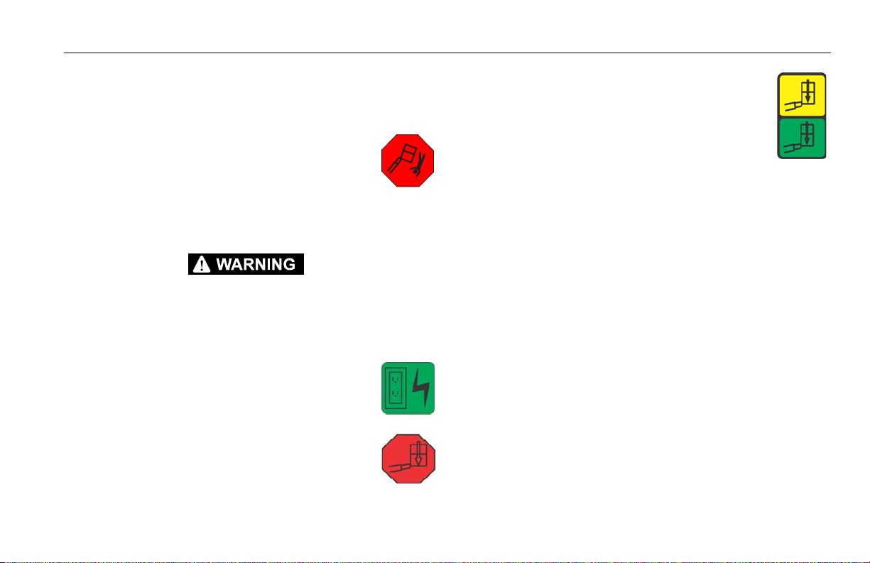
1. Level System Fault Indicator
Indicates a fault in the electronic leveling system. The fault indicator will flash and an alarm
sound. All functions will default to creep if the
boom is extended more than 20 inches (51 cm) or elevated
above horizontal.
IF THE LEVEL SYSTEM FAULT INDICATOR IS ILLUMINATED, SHUT DOWN THE
MACHINE, RECYCLE THE EMERGENCY STOP, AND RESTART THE MACHINE. IF THE
FAULT PERSISTS, RETURN THE PLATFORM TO THE STOWED POSITION, USING MANUAL LEVELING AS REQUIRED, AND HAVE LEVELING SYSTEM REPAIRED.
2. AC Generator (If Equipped)
Indicates the generator is in operation.
3. Platform Overload (If equipped)
Indicates the platform has been overloaded.
4. Capacity Indicator
Indicates the maximum platform capacity for
the current position of the platform. Restricted
capacities are permitted at restricted platform
positions (shorter boom lengths and higher
boom angles).
NOTE: Refer to the capacity decals on the machine for restricted and
unrestricted platform capacities.
3121678 – JLG Lift – 3-15

SECTION 3 - MACHINE CONTROLS AND INDICATORS
5. Tilt Alarm Warning Light and Alarm
This illuminator indicates that the chassis is on
a slope. An alarm will also sound when the
chassis is on a slope and the boom is above
horizontal. If lit when boom is raised or extended, retract
and lower to below horizontal then reposition machine so
that it is level before continuing operation. If the boom is
above horizontal and the machine is on a slope, the tilt
alarm warning light will illuminate and an alarm will sound
and CREEP is automatically activated.
IF TILT WARNING LIGHT IS ILLUMINATED WHEN BOOM IS RAISED OR EXTENDED,
RETRACT AND LOWER TO BELOW HORIZONTAL THEN REPOSITION MACHINE SO THAT
IT IS LEVEL BEFORE EXTENDING BOOM OR RAISING BOOM ABOVE HORIZONTAL.
NOTE: In certain markets, when the tilt sensor alarm is activated the
Drive function will be disabled if the boom is elevated above horizontal.
6. Glow Plug/Wait to Start Indicator
Indicates the glow plugs are operating. After
turning on ignition, wait until light goes out
before cranking engine.
7. Footswitch/Enable Indicator
To operate any function, the footswitch must
be depressed and the function selected within
seven seconds. The enable indicator shows
that the controls are enabled. If a function is not selected
within seven seconds, or if a seven second lapse between
ending one function and beginning the next function, the
enable light will go out and the footswitch must be released
and depressed again to enable the controls.
Releasing the footswitch removes power from all controls
and applies the drive brakes.
TO AVOID SERIOUS INJURY, DO NOT REMOVE, MODIFY OR DISABLE THE FOOTSWITCH
BY BLOCKING OR ANY OTHER MEANS.
FOOTSWITCH MUST BE ADJUSTED IF FUNCTIONS ACTIVATE WHEN SWITCH ONLY
OPERATES WITHIN LAST 1/4" OF TRAVEL, TOP OR BOTTOM.
3-16 – JLG Lift – 3121678

SECTION 3 - MACHINE CONTROLS AND INDICATORS
!
!
!
123 4*5678
91011**
* UNRESTRICT E D CAP A CITY
** RESTRICT ED CAPACITY
12
1. Level System
2. AC Generator
3. Overload
4. Capacity
5. Tilt Alarm Warning
6. Glow Plug
7. Enable
8. Fuel Level
9. Creep Speed
10. System Distress
11. Cable Service
12. Drive Orientation
Figure 3-3. Platform Control Indicator Panel
3121678 – JLG Lift – 3-17
SECTION 3 - MACHINE CONTROLS AND INDICATORS
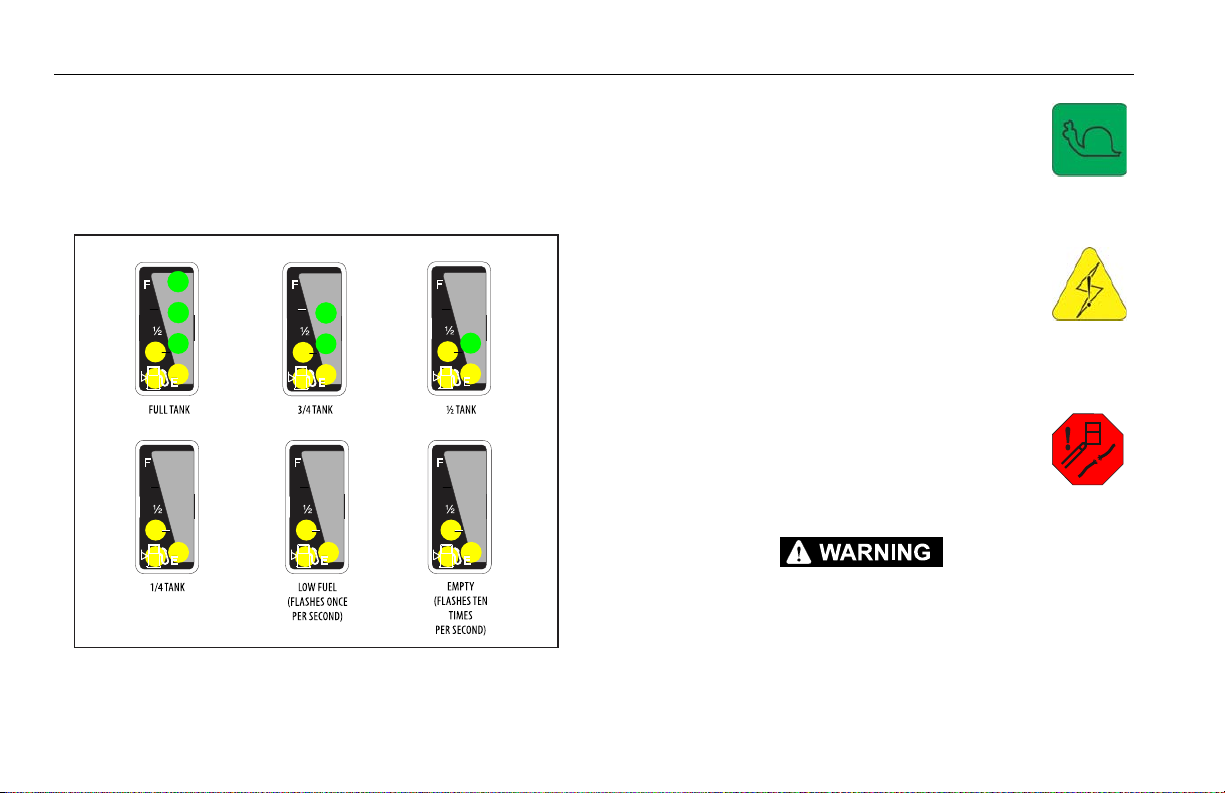
Figure 3-4. Fuel Level Indicator
NOTE: Refer to Fuel Reserve/Shut-Off System in Section 4 for more
detailed information concerning the Low Fuel Indicator.
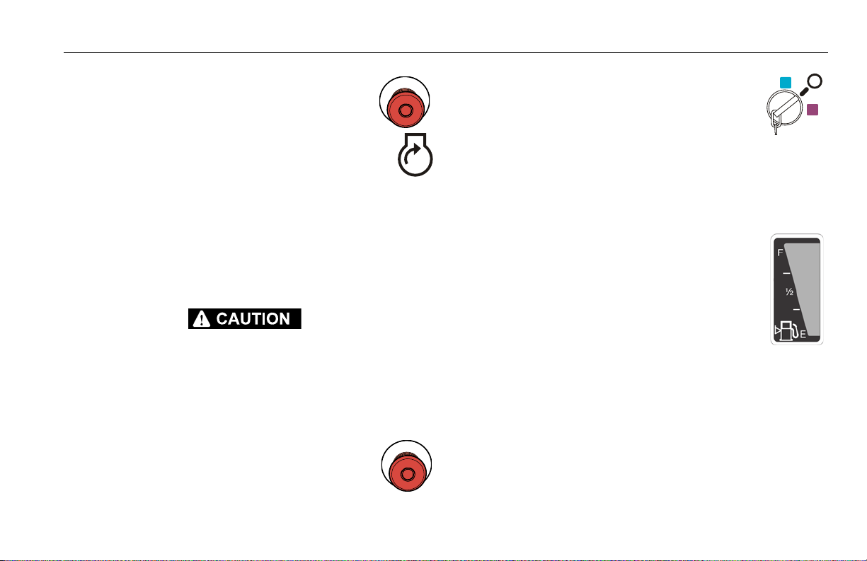
8. Fuel Level Indicator
Indicates the level of fuel in the fuel tank.
9. Creep Speed Indicator
When the Function Speed Control is turned to
the creep position, the indicator acts as a
reminder that all functions are set to the slowest speed.
10. System Distress Indicator
The light indicates that the JLG Control System
has detected an abnormal condition and a
Diagnostic Trouble Code has been set in the
system memory. Refer to the Service Manual for instructions
concerning the trouble codes and trouble code retrieval.
11. Cable Service Indicator (If Equipped)
When illuminated, the light indicates the
boom cables are loose or broken and must be
repaired or adjusted immediately.
IF THE CABLE SERVICE INDICATOR IS ILLUMINATED, RETURN THE PLATFORM TO THE
STOWED POSITION, SHUT DOWN THE MACHINE, AND HAVE THE BOOM CABLES
INSPECTED.
3-18 – JLG Lift – 3121678

12. Drive Orientation Indicator
When the boom is swung beyond the rear
drive tires or further in either direction, the
Drive Orientation indicator will illuminate
when the drive function is selected. This is a signal for the
operator to verify that the drive control is being operated in
the proper direction (i.e. controls reversed situations).
SECTION 3 - MACHINE CONTROLS AND INDICATORS
3121678 – JLG Lift – 3-19

SECTION 3 - MACHINE CONTROLS AND INDICATORS
NOTES:
3-20 – JLG Lift – 3121678

SECTION 4. MACHINE OPERATION
SECTION 4 - MACHINE OPERATION
4.1 DESCRIPTION
This machine is a self-propelled hydraulic lift equipped with a
work platform on the end of an elevating and rotating boom.
The primary operator control console is in the platform. From this
control console, the operator can drive and steer the machine in
both forward and reverse directions. The operator can raise or
lower the upper or lower boom or swing the boom to the left or
right. Standard boom swing is 360 degree continuous left and
right of the stowed position. The machine has a Ground Control
Console which will override the Platform Control Console.
Ground Controls operate Boom Lift and Swing, and are to be
used in an emergency to lower the platform to the ground
should the operator in the platform be unable to do so. The
Ground Control is also to be used in Pre-Start Inspection.
4.2 OPERATING CHARACTERISTICS AND LIMITATIONS
Capacities
The boom can be raised above horizontal with or without any
load in platform, if:
1. Machine is positioned on a smooth, firm and level surface.
2. Load is within manufacturer’s rated capacity.
3. All machine systems are functioning properly.
4. Proper tire pressure.
5. Machine is as originally equipped from JLG.
Stability
Machine stability is based on two (2) conditions which are called
FORWARD and BACKWARD stability. The machine’s position of
least FORWARD stability is shown in (See Figure 4-2.), and its position of least BACKWARD stability is shown in (See Figure 4-1.)
3121678 – JLG Lift – 4-1

SECTION 4 - MACHINE OPERATION
TO AVOID FORWARD OR BACKWARD TIPPING, DO NOT OVERLOAD MACHINE OR OPERATE THE MACHINE ON AN OUT-OF-LEVEL SURFACE.
4.3 ENGINE OPERATION
NOTE: Initial starting should always be per-
formed from the Ground Control console.
1. Turn key of Platform/Ground Select switch to
Ground.
2. Pull the Power/Emergency Stop switch to On.
3. Push the Engine Start switch until engine starts.
Starting Procedure
IF ENGINE FAILS TO START PROMPTLY, DO NOT CRANK FOR AN EXTENDED TIME.
SHOULD ENGINE FAIL TO START AGAIN, ALLOW STARTER TO “COOL OFF” FOR 2-3 MINUTES. IF ENGINE FAILS AFTER SEVERAL ATTEMPTS, REFER TO ENGINE MAINTENANCE
MANUAL.
NOTE: Diesel engines only: After turning on ignition,
operator must wait until glow plug indicator light
goes out before cranking engine.
ALLOW ENGINE TO WARM-UP FOR A FEW MINUTES AT LOW SPEED BEFORE APPLYING
ANY LOAD.
4. After engine has had sufficient time to warm
up, push in the Power/Emergency Stop switch
and shut engine off.
5. Turn Platform/Ground Select switch to Platform.
4-2 – JLG Lift – 3121678
SECTION 4 - MACHINE OPERATION
6. From Platform, pull Power/Emergency Stop
switch out.
7. Push the Engine Start switch until engine
starts.
NOTE: Footswitch must be in released (up) position before starter will
operate. If starter operates with footswitch in the depressed position, DO NOT OPERATE MACHINE.
Shutdown Procedure
IF AN ENGINE MALFUNCTION CAUSES AN UNSCHEDULED SHUTDOWN, DETERMINE
THE CAUSE AND CORRECT IT BEFORE RESTARTING THE ENGINE.
1. Remove all load and allow engine to operate at low speed
for 3-5 minutes; this allows further reduction of internal
engine temperature.
2. Push Power/Emergency Stop switch in.
3. Turn Platform/Ground Select switch to Off.
Refer to Engine Manufacturer’s manual for detailed
information.
Fuel Reserve / Shut-Off System
NOTE: Reference the Service and Maintenance Manual along with a
qualified JLG Mechanic to verify your machine setup.
The Fuel Shutoff System monitors the fuel in the
tank and senses when the fuel level is getting low.
The JLG Control System automatically shuts the
engine down before the fuel tank is emptied unless
the machine is set up for Engine Restart.
If fuel level reaches the Empty range, the Low Fuel
light will begin to flash once a second and there will
be approximately 60 minutes of engine run time
left. If the system is in this condition and automatically shuts
down the engine or if the operator manually shuts down the
engine before the 60 minute run time is complete, the Low Fuel
light will flash 10 times a second and the engine will react according to machine setup. Setup options are as follows:
• Engine One Restart - When the engine shuts down, the
operator will be permitted to cycle power and restart the
engine once with approximately 2 minutes of run time.
3121678 – JLG Lift – 4-3

SECTION 4 - MACHINE OPERATION
Figure 4-1. Position of Least Backward Stability
ROTATE PLATFORM
90 DEGREES
BOOM FULLY
ELEVATED
TURNTABLE ROTATED
90 DEGREES FROM
STOWED POSITION
MACHINE WILL TIP OVER IN
THIS DIRECTION IF OVERLOADED
OR OPERATED
ON AN OUT-OF-LEVEL SURFACE
After the 2 minute run time is complete or if the engine is
shut down by the operator prior to the completion of the 2
minute run time, it cannot be restarted until fuel is added
to the tank.
• Engine Restart - When the engine shuts down, the operator will be permitted to cycle power and restart the engine
for approximately 2 minutes of run time. After the 2 minutes of run time is complete, the operator may cycle power
and restart the engine for an additional 2 minutes of run
time. The operator can repeat this process until there is no
more fuel available.
• Engine Stop - When the engine shuts down, no restarts
will be permitted until fuel is added to the tank.
.
4-4 – JLG Lift – 3121678

Figure 4-2. Position of Least Forward Stability
MACHINE WILL TIP OVER IN
THIS DIRECTION IF OVERLOADED
OR OPERATED
ON AN OUT-OF-LEVEL SURFACE
TELESCOPE
FULLY EXTENDED
TURNTABLE ROTATED
90 DEGREES FROM
STOWED POSITION
SECTION 4 - MACHINE OPERATION
3121678 – JLG Lift – 4-5

SECTION 4 - MACHINE OPERATION
4.4 TRAVELING (DRIVING)
NOTE: When the upper boom is raised approximately 11 degrees above
horizontal, the high drive function will automatically be in low
drive.
NOTE: Refer to the Operating Specifications table for Gradeability and
Sideslope ratings.
All ratings for Gradeability and Sideslope are based upon the
machine’s boom being in the stowed position, fully lowered, and
retracted.
Traveling is limited by two factors:
1. Gradeability, which is the percent of grade of the incline the
machine can climb.
2. Sideslope, which is the angle of the slope the machine can
be driven across.
DO NOT DRIVE WITH BOOM ABOVE HORIZONTAL EXCEPT ON A SMOOTH, FIRM AND
LEVEL SURFACE.
TO AVOID LOSS OF TRAVEL CONTROL OR “TIP OVER”, DO NOT DRIVE MACHINE ON
GRADES EXCEEDING THOSE SPECIFIED ON THE SERIAL NUMBER PLATE.
BE SURE THE TURNTABLE LOCK IS ENGAGED BEFORE ANY EXTENDED TRAVELING.
DO NOT DRIVE ON SIDESLOPES WHICH EXCEED 5 DEGREES.
USE EXTREME CAUTION WHEN DRIVING IN REVERSE AND AT ALL TIMES WHEN THE
PLATFORM IS ELEVATED.
BEFORE DRIVING, MAKE SURE BOOM IS POSITIONED OVER REAR DRIVE AXLE. IF
BOOM IS OVER FRONT WHEELS, STEER AND DRIVE CONTROLS WILL BE REVERSED.
4-6 – JLG Lift – 3121678
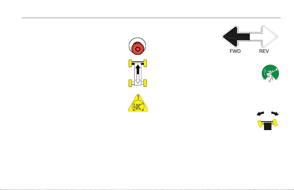
SECTION 4 - MACHINE OPERATION
Traveling Forward and Reverse
1. At Platform Controls, pull out Emergency Stop
switch and activate footswitch.
2. Position Drive controller to FORWARD or
REVERSE as desired.
This machine is equipped with a Drive Orientation
Indicator. The yellow light on the platform control
console indicates that the boom is swung beyond
the rear drive tires and the machine may Drive/
Steer in the opposite direction from the movement
of the controls. If the indicator is illuminated, operate the Drive
function in the following manner:
1. Match the black and
white direction arrows
on both platform control panel and the chassis to determine the
direction the machine
will travel.
2. Push and release the Drive Orientation Override switch. Within 3 seconds, slowly move the
Drive control toward the arrow matching the
intended direction of machine travel. The indicator light will flash during the 3 second interval until the drive function is selected.
4.5 STEERING
Position thumb switch on Drive/Steer controller
to Right for steering right, or to Left for steering
left.
3121678 – JLG Lift – 4-7

SECTION 4 - MACHINE OPERATION
Figure 4-3. Grade and Side Slopes
4-8 – JLG Lift – 3121678

SECTION 4 - MACHINE OPERATION
4.6 PLATFORM
Platform Level Adjustment
ONLY USE THE PLATFORM LEVELING OVERRIDE FUNCTION FOR SLIGHT LEVELING OF
THE PLATFORM. INCORRECT USE COULD CAUSE THE LOAD/OCCUPANTS TO SHIFT OR
FALL. FAILURE TO DO SO COULD RESULT IN DEATH OR SERIOUS INJURY.
To Level Up or Down - Position the Platform/Level
control switch Up or Down and hold until the platform is level.
Platform Rotation
To rotate the platform to the left or right, use the
Platform Rotate control switch to select the direction and hold until desired position is reached.
4.7 BOOM
DO NOT SWING OR RAISE BOOM ABOVE HORIZONTAL WHEN MACHINE IS OUT OF
LEVEL.
DO NOT DEPEND ON TILT ALARM AS A LEVEL INDICATOR FOR THE CHASSIS.
TO AVOID TIP OVER, LOWER PLATFORM TO GROUND LEVEL. THEN DRIVE MACHINE TO
A LEVEL SURFACE BEFORE RAISING BOOM.
TO AVOID SERIOUS INJURY, DO NOT OPERATE MACHINE IF ANY CONTROL LEVER OR
TOGGLE SWITCH CONTROLLING PLATFORM MOVEMENT DOES NOT RETURN TO THE
‘OFF’ OR NEUTRAL POSITION WHEN RELEASED.
IF THE PLATFORM DOES NOT STOP WHEN A CONTROL SWITCH OR LEVER IS RELEASED,
REMOVE FOOT FROM FOOTSWITCH OR USE EMERGENCY STOP SWITCH TO STOP THE
MACHINE.
3121678 – JLG Lift – 4-9

SECTION 4 - MACHINE OPERATION
Swinging the Boom
To swing boom, use Swing control switch to select
Right or Left direction.
WHEN SWINGING THE BOOM MAKE SURE THERE IS AMPLE ROOM FOR THE BOOM TO
CLEAR SURROUNDING WALLS, PARTITIONS AND EQUIPMENT.
NOTE: On CE Market machines, when boom functions are being oper-
ated there is an interlock that prevents the use of Drive and Steer
functions.
Raising and Lowering the Boom
To raise or lower the Boom, position the Boom Lift control to Up or Down until the desired height is reached.
Telescoping the Main Boom
To extend or retract the boom, use the Telescope
Control Switch to select In or Out movement.
4.8 FUNCTION SPEED CONTROL
This control affects the speed of all boom functions and Platform Rotate. Turning the knob all
the way counterclockwise till it clicks places Drive
in creep speed.
4.9 OSCILLATING AXLE LOCKOUT TEST (IF EQUIPPED)
LOCKOUT SYSTEM TEST MUST BE PERFORMED QUARTERLY, ANY TIME A SYSTEM COMPONENT IS REPLACED, OR WHEN IMPROPER SYSTEM OPERATION IS SUSPECTED.
Refer to Section 2.4, Oscillating Axle Lockout Test (If Equipped) for
procedure.
4-10 – JLG Lift – 3121678

4.10 EMERGENCY TOWING
Figure 4-4. Drive Disconnect Hub
RUNAWAY VEHICLE/MACHINE HAZARD. MACHINE HAS NO TOWING BRAKES. TOWING
VEHICLE MUST BE ABLE TO CONTROL MACHINE AT ALL TIMES. ON-HIGHWAY TOWING
NOT PERMITTED. FAILURE TO FOLLOW INSTRUCTIONS COULD CAUSE SERIOUS INJURY
OR DEATH.
MAXIMUM TOWING SPEED 5 M.P.H. (8 K.M.H.)
MAXIMUM TOWING GRADE 25%.
DO NOT TOW MACHINE WITH ENGINE OPERATING OR DRIVE HUBS ENGAGED.
1. Retract, lower and position boom in travel position; lock
turntable.
2. Disconnect drive hubs by inverting disconnect cap.
SECTION 4 - MACHINE OPERATION
3. Reconnect the drive hubs by inverting the disconnect cap
when towing is complete.
3121678 – JLG Lift – 4-11

SECTION 4 - MACHINE OPERATION
4.11 TOW BAR (IF EQUIPPED)
RUNAWAY VEHICLE/MACHINE HAZARD. MACHINE HAS NO TOWING BRAKES. TOWING
VEHICLE MUST BE ABLE TO CONTROL MACHINE AT ALL TIMES. ON-HIGHWAY TOWING
NOT PERMITTED. FAILURE TO FOLLOW INSTRUCTIONS COULD CAUSE SERIOUS INJURY
OR DEATH.
MAXIMUM TOWING SPEED 5 M.P.H. (8 K.M.H.)
MAXIMUM TOWING GRADE 25%.
Prior to towing the machine, complete the following:
DO NOT TOW MACHINE WITH ENGINE OPERATING OR DRIVE HUBS ENGAGED.
1. Retract, lower and position boom in travel position; lock
turntable.
2. Lower towbar and connect to towing vehicle
.
3. Disconnect drive hubs by inverting disconnect cap. Refer to
Figure 4-4., Drive Disconnect Hub.
4. Position steer/tow selector valve for towing; pull valve knob
OUT for towing. The machine is now in the towing mode.
4-12 – JLG Lift – 3121678

After towing the machine, complete the following:
1. Actuate steer/tow selector valve for steering; push valve
knob IN to the actuated position.
2. Reconnect drive hubs by inverting disconnect cap.
3. Disconnect towbar from towing vehicle and place it in the
stowed position as shown below. The machine is now in the
driving mode.
SECTION 4 - MACHINE OPERATION
3121678 – JLG Lift – 4-13

SECTION 4 - MACHINE OPERATION
4.12 SHUT DOWN AND PARK
To shut down and park the machine, the procedures are as follows:
1. Drive machine to a reasonably well protected area.
2. Ensure boom is lowered over rear drive axle.
3. Push in the Emergency Stop at Platform Controls.
4. Push in the Emergency Stop at Ground Controls. Position
Platform/Ground Select switch to center OFF.
5. If necessary, cover Platform Controls to protect instruction
placards, warning decals and operating controls from hostile
environment.
4.13 LIFTING AND TIE DOWN
Lifting
1. Refer to the Serial Number Plate, refer to the Specifications section of this manual, or weigh the individual unit
to find out the Gross Vehicle Weight.
2. Place the boom in the stowed position.
3. Remove all loose items from the machine.
4. Attach lifting device and equipment only to the designated lifting points.
5. Properly adjust the rigging to prevent damage to the
machine and so the machine remains level.
4-14 – JLG Lift – 3121678

Tie Down
WHEN TRANSPORTING THE MACHINE, THE BOOM MUST BE FULLY LOWERED INTO
THE BOOM REST.
1. Remove all loose items from the machine.
2. When transporting an 800S/860SJ a step-deck or single-
drop trailer is required. To avoid damage to the platform and
to obtain proper weight distribution, load the machine onto
the trailer as follows;
a. Position the boom over the front wheels.
DO NOT SWING THE BOOM WHIT THE MACHINE POSITIONED ON A TRAILER. TIPOVER
MAY RESULT
b. Place the boom in the stowed position with the turnta-
ble locked.
SECTION 4 - MACHINE OPERATION
DRIVE AND STEER CONTROLLERS WILL BE REVERSED WHEN THE BOOM IS POSITIONED OVER THE FRONT WHEELS.
c. Drive it onto the trailer with the boom and platform
positioned towards the truck.
3. Secure the chassis and the platform using straps or chains of
adequate strength.
3121678 – JLG Lift – 4-15

SECTION 4 - MACHINE OPERATION
Figure 4-5. Lifting and Tie Down Chart
4-16 – JLG Lift – 3121678

SECTION 4 - MACHINE OPERATION
Figure 4-6. Decal Location - Sheet 1 of 5
3121678 – JLG Lift – 4-17

SECTION 4 - MACHINE OPERATION
Figure 4-7. Decal Location - Sheet 2 of 5
4-18 – JLG Lift – 3121678

SECTION 4 - MACHINE OPERATION
Figure 4-8. Decal Location - Sheet 3 of 5
3121678 – JLG Lift – 4-19
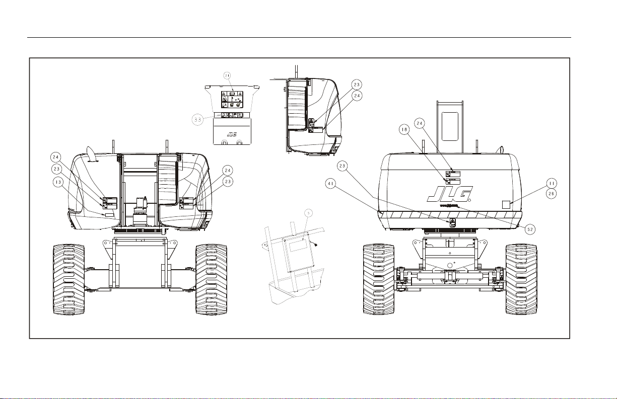
SECTION 4 - MACHINE OPERATION
Figure 4-9. Decal Location - Sheet 4 of 5
4-20 – JLG Lift – 3121678

SECTION 4 - MACHINE OPERATION
Figure 4-10. Decal Location - Sheet 5 of 5
3121678 – JLG Lift – 4-21
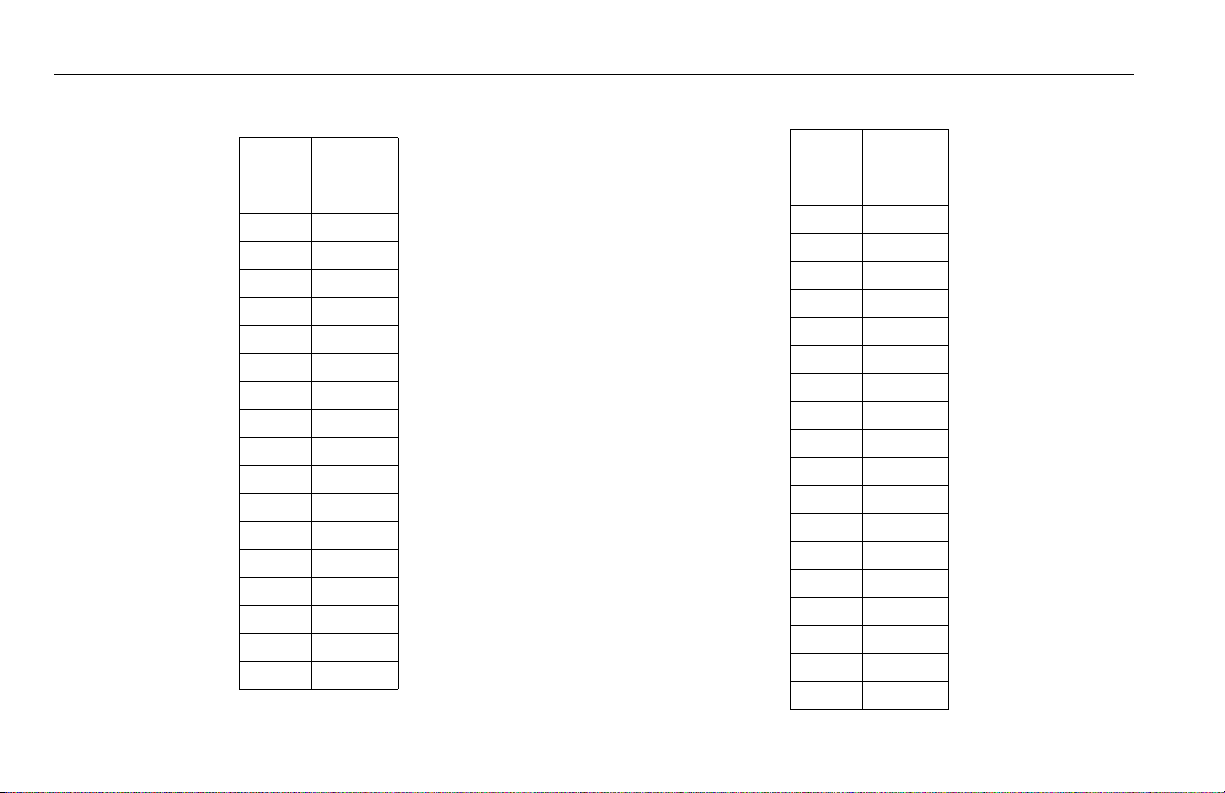
SECTION 4 - MACHINE OPERATION
Table 4-1. Decal Location Legend
CE/
Item #
Australia
0275865-E
1- -
2 1701499
3 1701502
4 1701503
5 1701509
6- -
7 1703811
8 1703814
9 1704277
10 1704412
11 1705980
12 - -
13 - -
14 - -
15 - -
16 - -
17 1702153
Table 4-1. Decal Location Legend
CE/
Item #
Australia
0275865-E
18 - -
19 - -
20 - -
21 1705921
22 1705822
23 1701518
24 1705961
25 1705828
26 - -
27 - -
28 - -
29 1703478
30 1702631
31 1707124
32 1701501
33 1705978
34 1705978
35 - -
4-22 – JLG Lift – 3121678

SECTION 4 - MACHINE OPERATION
Table 4-1. Decal Location Legend
CE/
Item #
Australia
0275865-E
36 - -
37 - -
38 - -
39 3252781
40 1701691
41 - -
42 - -
43 - -
44 - -
45 - -
46 - -
47 - -
48 - -
49 - -
50 - -
51 - -
52 - -
53 - -
Table 4-1. Decal Location Legend
CE/
Item #
Australia
0275865-E
54 - -
55 - -
56 - -
57 - -
58 - -
59 1704277
3121678 – JLG Lift – 4-23

SECTION 4 - MACHINE OPERATION
NOTES:
4-24 – JLG Lift – 3121678

5.1 GENERAL
SECTION 5 - EMERGENCY PROCEDURES
SECTION 5. EMERGENCY PROCEDURES
This section explains the steps to be taken in case of an emergency situation while operating.
5.2 INCIDENT NOTIFICATION
JLG Industries, Inc. must be notified immediately of any incident
involving a JLG product. Even if no injury or property damage is
evident, the factory should be contacted by telephone and provided with all necessary details.
In USA:
JLG Phone: 877-JLG-SAFE (554-7233)
Outside USA:
240-420-2661
E-mail:
ProductSafety@JLG.com
Failure to notify the manufacturer of an incident involving a JLG
Industries product within 48 hours of such an occurrence may
void any warranty consideration on that particular machine.
FOLLOWING ANY ACCIDENT, THOROUGHLY INSPECT THE MACHINE AND TEST ALL
FUNCTIONS FIRST FROM THE GROUND CONTROLS, THEN FROM THE PLATFORM CONTROLS. DO NOT LIFT ABOVE 3 M (10 FT.) UNTIL YOU ARE SURE THAT ALL DAMAGE HAS
BEEN REPAIRED, IF REQUIRED, AND THAT ALL CONTROLS ARE OPERATING CORRECTLY.
5.3 EMERGENCY OPERATION
Operator Unable to Control Machine
IF THE PLATFORM OPERATOR IS PINNED, TRAPPED OR UNABLE TO
OPERATE OR CONTROL MACHINE:
1. Other personnel should operate the machine from ground
controls only as required.
2. Other qualified personnel on the platform may use the platform controls. DO NOT CONTINUE OPERATION IF CONTROLS
DO NOT FUNCTION PROPERLY.
3. Cranes, forklift trucks or other equipment can be used to
remove platform occupants and stabilize motion of the
machine.
3121678 – JLG Lift – 5-1

SECTION 5 - EMERGENCY PROCEDURES
Platform or Boom Caught Overhead
If the platform or boom becomes jammed or snagged in overhead structures or equipment, rescue platform occupants prior to
freeing the machine.
Boom Movement Prevented By Boom Control System
Lowering the boom onto an object or structure, with the boom at
high angles, may cause the boom control system to prevent
movement of the machine. This can include movement necessary
to lift the boom off the object. Movement of the boom can be
regained by observing the following:
1. Shut off the engine.
2. Rescue platform occupants prior to freeing machine.
3. Use cranes, forklifts or other equipment to stabilize motion
of the machine as required.
4. From the ground control position, use the Auxiliary Power
System to carefully raise the boom off the object.
5. Once clear, restart the engine and return the platform to the
ground.
6. Inspect the machine for damage before continued use of the
machine.
5.4 EMERGENCY TOWING PROCEDURES
Towing this machine is prohibited, unless properly equipped.
However, provisions for moving the machine have been incorporated. For specific procedures, refer to Section 4.
5-2 – JLG Lift – 3121678

SECTION 6 - GENERAL SPECIFICATIONS & OPERATOR MAINTENANCE
SECTION 6. GENERAL SPECIFICATIONS & OPERATOR MAINTENANCE
6.1 INTRODUCTION
This section of the manual provides additional necessary information to the operator for proper operation and maintenance of
this machine.
The maintenance portion of this section is intended as information to assist the machine operator to perform daily maintenance
tasks only, and does not replace the more thorough Preventive
Maintenance and Inspection Schedule included in the Service
and Maintenance Manual.
Other Publications Available:
Service and Maintenance Manual .............................................3121679
Illustrated Parts Manual ...............................................................3121680
6.2 OPERATING SPECIFICATIONS
Table 6-1. Operating Specifications
Maximum Work Load (Capacit y)
Un r es t ri c te d :
Re s tr i c te d
Maximum Travel Grade (Gradeability)*
2W D
4W D
Maximum Travel Grade (Side Slope)* 5°
Maximum Vertical Platform Height: 68 ft. (20.7 m)
Maximum Horizontal Platform Reach 59 ft. (17.9 m)
Turning Radius (outside) 22 ft. 6 in. (6.8 m)
Turning Radius (inside) 12 ft. (3.6 m)
Maximum Drive Speed: 3.5 mph (1.5 m/s)
Max. Hydraulic System Pressure 4500 psi (310 Bar)
Maximum Wind Speed 28 mph (12.5 m/s)
Maximum Manual Force 400 N
Electrical System Voltage 12 Volts
Refer to Capacity Decals on machine for
restric ted platform capacities
500 lb (227 kg)
30%
45%
3121678 – JLG Lift – 6-1

SECTION 6 - GENERAL SPECIFICATIONS & OPERATOR MAINTENANCE
Table 6-1. Operating Specifications
Gross Machine Weight (Platform Empty) 32675 lbs. (14,821 kg)
* With boom in stowed position
Specifications and Performance Data
Table 6-2. Specifications and Performance Data
Swing 360°
Tai l S wi n g 4’ 8" ( 1. 42 m)
Platform 48" x 160" (1.22 m x 4.06m)
Overall Width 8’ 2" (2.5 m)
Stowed Height 9’ 10" (2.97 m)
Stowed Length 38’ 5" (11.72 m)
Wheel base 10’ 1" (3.1 m)
Ground Clearance 12.4" (0.31m)
Drive Speed
St o we d 2W D
St o we d 4W D
El e va t ed
Ground Bearing Pressure
18 - 6 25
Max. Tire Load
18-625 18,300 lbs. (8300 kg)
3.0 mph (5.5 kph)
3.5 mph (5.6 kph)
0.75 mph (1.2 kph)
71.5 psi (4.95 kgm/cm2)
6-2 – JLG Lift – 3121678

SECTION 6 - GENERAL SPECIFICATIONS & OPERATOR MAINTENANCE
Capacities Engine Data
Table 6-3. Capacities
Table 6-4. Deutz D2011L04 Specifications
Fuel Tank Approx. 31 gallons (117 liters)
Fuel Tank (Optional) Approx. 52.8 gallons (200 liters)
Hydraulic Tank Approx. 21 gallons (79.5 liters)
Engine Oil Capacity
D eu t z D 2 01 1 L0 4
Co o li n g S y st e m
Cr a nk c as e
Tot a l C a pa c it y
D eu t z T D 2. 9 L
G M
4.5 Quarts (4.25 L) w/Filter
5 Quarts (4.5 L)
11 Quarts (10.5 L) w/Filter
16 Quarts (15 L)
2.4 Gallon (8.9 L) w/Filter
Type Liquid Cooled (Oil)
Fuel Diesel
Oil Capacity
Co o li n g S y st e m
Cr a nk c as e
Tot a l C a pa c it y
Idle RPM 1000
Low RPM 1800
High RPM 2600
Alternator 55 Amp, belt drive
Fuel Consumption 0.88 GPH (3.33 lph)
Battery 1000 Cold Cranking Amps, 210 minutes
Horsepower 61.6 @ 2600 RPM, full load
5 Quarts (4.5 L)
11 Quarts (10.5 L) w/Filter
16 Quarts (15 L)
Reserve Capacity, 12 VDC
3121678 – JLG Lift – 6-3

SECTION 6 - GENERAL SPECIFICATIONS & OPERATOR MAINTENANCE
Table 6-5. Deutz TD 2.9 Specifications
Fuel Ultra Low Sulfur Diesel (15 ppm)
Output 67 hp (50 kW)
Torque 173 ft.lbs. (234 Nm) @ 1800rpm
Oil Capacity (Crankcase) 2.4 Gallon (8.9 L) w/Filter
Cooling System 3.3 Gallon (12.5 L)
Low RPM 1200 ±50 rpm
High RPM 2600±50 rpm
Alternator 95 Amp
Fuel Consumption 0.65 GPH (2.48 lph)
Table 6-6. GM 3.0L
Fuel Gasoline or Gasoline/LP Gas
No. of Cylinders 4
BHP
Ga s ol i n e
LP
83 hp @ 3000 rpm
75 hp @ 3000 rpm
Bore 4.0 in. (101.6 mm)
Stroke 3.6 in. (91.44 mm)
Displacement 181 cu.in. (3.0 L, 2966 cc)
Oil Capacity w/filter 4.5 qts. (4.25 L)
Minimum Oil Pressure
at i dl e
Ho t
6 psi (0.4 Bar) @ 1000 rpm
18 psi (1.2 Bar) @ 2000 rpm
Compression Ratio 9.2:1
Firing Order 1-3-4-2
Max. RPM 2800
6-4 – JLG Lift – 3121678

SECTION 6 - GENERAL SPECIFICATIONS & OPERATOR MAINTENANCE
Battery Tires
Table 6-7. Battery Specifications
Voltage 12 Volt
Type 31-950
Cold Cranking Amps 950 CCA @ 0° F (-18° C)
Reserve Capacity 205 Minutes @ 80° F (27° C)
Table 6-8. Tire Specifications
Size Type Ply Rating
18-625 foam-filled 16 H N/A
Load
Range
Pressure
3121678 – JLG Lift – 6-5

SECTION 6 - GENERAL SPECIFICATIONS & OPERATOR MAINTENANCE
Major Component Weights Hydraulic Oil
Table 6-9. Component Weights
Component Pound s Kilograms
Turntable (bare) 3700 1678
Counterweight 7000 3175
Upright 1050 476
Tow er 6 85 31 1
Fly Boom 490 222
Mid Boom 740 336
Base Boom 1410 640
Boom Assembly 3337 1514
Telescope Cyl inder 495 225
Slave Cylinder 73 33
Tor q ue H ub (2 W D) 21 8 9 9
Tire & Wheel (pneu) 269 122
Tire & Wheel (FF) 544 247
NOTE: Hydraulic oils must have anti-wear qualities at least to API Ser-
NOTE: When temperatures remain consistently below 20 degrees F. (-7
Temperature Range
+0° to + 180° F (-18° to +83° C) 10W
+0° to + 210° F (-18° to +99° C) 10W-20, 10W30
+50° to + 210° F (+10° to +99° C 20W-20
vice Classification GL-3, and sufficient chemical stability for
mobile hydraulic system service. JLG Industries recommends
Mobilfluid 424 hydraulic oil, which has an SAE viscosity index of
152.
degrees C.), JLG Industries recommends the use of Mobil DTE13.
Table 6-10. Hydraulic Oil
Hydraulic System
Operating
S.A.E. Viscosity
Grade
6-6 – JLG Lift – 3121678

SECTION 6 - GENERAL SPECIFICATIONS & OPERATOR MAINTENANCE
Table 6-11. Mobilfluid 424 Specs
SAE Grade 10W30
Gravity, API 29.0
Density, Lb/Gal. 60°F 7.35
Pour Point, Max -46°F (-43°C)
Flash Point, Min. 442°F (228°C)
Viscosity
Brookfield, cP at -18°C 2700
at 40° C 55 cSt
at 100° C 9.3 cSt
Viscosity Index 152
Aside from JLG recommendations, it is not advisable to mix oils of different brands or types, as they may not contain the same required additives or be of comparable viscosities. If use of hydraulic oil other than
Mobilfluid 424 is desired, contact JLG Industries for proper recommendations.
3121678 – JLG Lift – 6-7
Table 6-12. UCon Hydrolube HP-5046
Type Synthetic Biodegradable
Specific Gravity 1.082
Pour Point, Max -58°F (-50°C)
pH 9.1
Viscosit y
at 0° C (32° F) 340 cSt (1600SUS)
at 40° C (104° F) 46 cSt (215SUS)
at 65° C (150° F) 22 cSt (106SUS)
Viscosity Index 170

SECTION 6 - GENERAL SPECIFICATIONS & OPERATOR MAINTENANCE
Table 6-13. Mobil DTE 13M Specs
ISO Viscosity Grade #32
Specific Gravity 0.877
Pour Point, Max -40°F (-40°C)
Flash Point, Min. 330°F (166°C)
Viscosity
at 40° C 33cSt
at 100° C 6.6 cSt
at 100° F 169 SUS
at 210° F 48 SUS
cp at -20° F 6,200
Viscosity Index 140
Table 6-14. Mobil EAL 224H Specs
Type Synthetic Biodegradable
ISO Viscosity Grade 32/46
Specific Gravity .922
Pour Point, Max -25°F (-32°C)
Flash Point, Min. 428°F (220°C)
Operating Temp. 0 to 180°F (-17 to 162°C)
Weight 7.64 lb. per gal.
(0.9 kg per liter)
Viscosit y
at 40° C 37 cSt
at 100° C 8.4 cSt
Viscosity Index 213
NOTE: Must be stored above 32°F (14°C)
6-8 – JLG Lift – 3121678
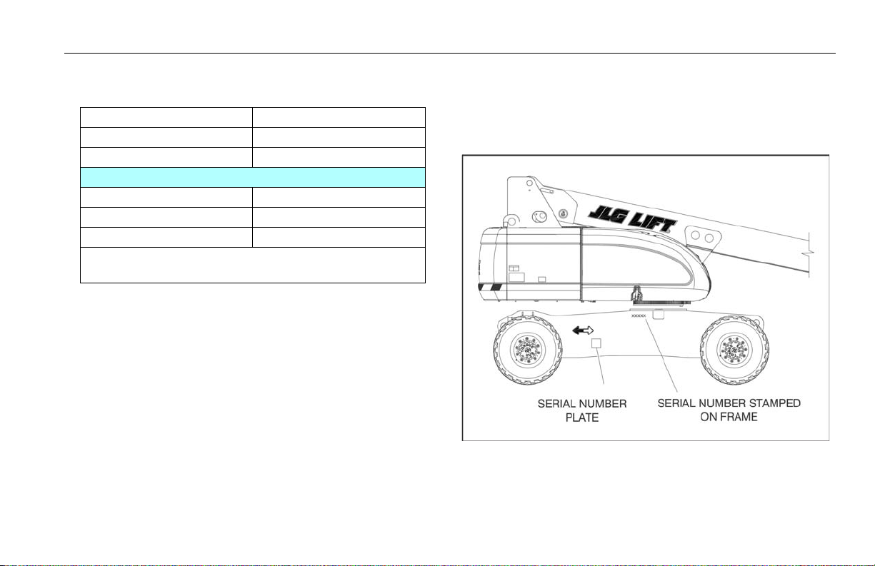
Table 6-15. Exxon Univis HVI 26 Specs
Specific Gravity 32.1
Pour Point -76°F (-60°C)
Flash Point 217°F (103°C)
Viscosity
at 40° C 25.8 cSt
at 100° C 9.3 cSt
Viscosity Index 376
NOTE: Mobil/Exxon recommends that this oil be checked on a
yearly basis for viscosity.
Figure 6-1. Serial Number Locations
SECTION 6 - GENERAL SPECIFICATIONS & OPERATOR MAINTENANCE
6.3 SERIAL NUMBER LOCATION
A serial number plate is affixed to the left rear side of the frame. If the
serial number plate is damaged or missing, the machine serial number is stamped on the left side of the frame.
3121678 – JLG Lift – 6-9

SECTION 6 - GENERAL SPECIFICATIONS & OPERATOR MAINTENANCE
-40°F(-40°C)
-30F°(-34°C)
-20°F(-29°C)
-10°F(-23°C)
0°F(-18°C)
10°F(-12°C)
20°F(-7°C)
30°F(-1°C)
40°F(4°C)
50°F(10°C)
60°F(16°C)
70°F(21°C)
80°F(27°C)
90°F(32°C)
100°F(38°C)
110°F(43°C)
120°F(49°C)
ENGINE
SPECIFICATIONS
ENGINE WILL START AND OPERATE AT THIS TEMPERATURE
WITH THE RECOMMENDED FLUIDS, A FULLY CHARGED BATTERY
AND THE AID OF A COMPLETE JLG SPECIFIED COLD WEATHER
PACKAGE (IE. ENGINE BLOCK HEATER, ETHER INJECTION OR
ENGINE WILL STAR T AND OPERATE UNAIDED AT THIS
TEMPERATURE WITH THE RECOMMENDED FLUIDS AND A
FULLY CHARGED BATTERY.
AMBIENT AIR
TEMPERATURE
SUMMER
GRADE
FUEL
WINTER
GRADE
FUEL
WINTER
GRADE
FUEL
WITH
KEROSENE
ADDED
NO OPERATION BELOW THIS
AMBIENT TEMPERATURE
NO OPERATION ABOVE THIS
AMBIENT TEMPERATURE
Figure 6-2. Engine Operating Temperature Specifications - Deutz - Sheet 1 of 2
6-10 – JLG Lift – 3121678
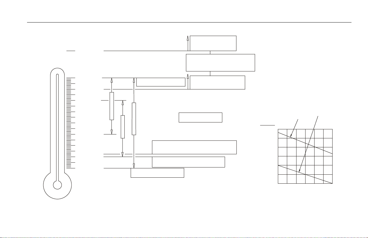
SECTION 6 - GENERAL SPECIFICATIONS & OPERATOR MAINTENANCE
(HYD. OIL TANK TEMP.)
IF EITHER OR BOTH CONDITIONS
EXIST JLG HIGHLY RECOMMENDS
THE ADDITION OF A HYDRAULIC
OIL COOLER (CONSULT JLG SERVICE
180° F (82° C)
-40° F (-40° C)
-30° F (-34° C)
-20° F (-29° C)
-10° F (-23° C)
0° F (-18° C)
10° F (-12° C)
20° F (-7° C)
30° F (-1° C)
40° F (4° C)
50° F (10° C)
60° F (16° C)
70° F (21° C)
80° F (27° C)
90° F (32° C)
100° F (38° C)
110° F (43° C)
120° F (49° C)
AMBIENT AIR
TEMPERATURE
PROLONGED OPERATION IN
AMBIENT AIR TEMPERATURES
OF 100°F(38°C) OR ABOVE.
EXTENDED DRIVING WITH
HYDRAULIC OIL TANK
TEMPERATURES OF 180°F
(82°C) OR ABOVE.
NO OPERATION BELOW THIS
AMBIENT TEMPERATURE
M
O
B
I
L
4
2
4
1
0
W
-
3
0
HYDRAULIC
SPECIFICATION S
NO OPERATION ABOVE THIS
AMBIENT TEMPERATURE
DO NOT START UP HYDRAULIC SYSTEM
WITHOUT HEATING AIDS WITH MOBILE 424
HYDRAULIC OIL BELOW THIS TEMPERATURE
DO NOT START UP HYDRAULIC SYSTEM
WITHOUT HEATING AIDS AND COLD WEATHER
HYDRAULIC OIL BELOW THIS TEMPERATURE
E
X
X
O
N
U
N
I
V
I
S
H
V
I
2
6
M
O
B
I
L
D
T
E
1
3
NOTE:
1) RECOMMENDAT IONS ARE FOR AMBIE NT TEMPERATURES
CO NSISTANT LY WIT HIN SHOWN LIMIT S
2) ALL VALUES ARE ASSUMED T O BE AT SEA LEVE L.
0+32
-5
-10
-15
-20
-25
-30
+23
+14
+5
-4
-13
-22
CF
0 102030405060
% OF ADDED KE ROSENE
A
M
B
I
E
N
T
T
E
M
P
E
R
A
T
U
R
E
SUMMER-GR ADE
FUEL
WINT ER-GRADE
FUEL
Figure 6-3. Engine Operating Temperature Specifications - Deutz - Sheet 2 of 2
4150548-E
3121678 – JLG Lift – 6-11

SECTION 6 - GENERAL SPECIFICATIONS & OPERATOR MAINTENANCE
-40 F(-40 C)
-30 F(-34 C)
-20 F(-29 C)
-10 F(-23 C)
0F(-18C)
10 F(-12 C)
20 F(-7 C)
30 F(-1 C)
40 F(4 C)
50 F(10 C)
60 F(16 C)
70 F(21 C)
80 F(27 C)
90 F(32 C)
100 F(38 C)
110 F(43 C)
120 F(49 C)
ENGINE WILL START AND OPERATE ON LPG UNAIDED AT THIS TEMPERATURE
WITH THE RECOMMENDED FLUIDS AND A FULLY CHARGED BATT ERY.
NOTE: THIS IS THE LOWEST ALLOWABLE OPERATING TEMPERATURE ON LPG.
ENGINE WILL START AND OPERATE ON GASOLINE UNAIDED AT THIS TEMPERATURE
WITH THE RECOMMENDED FLUIDS AND A FULLY CHARGED BATTERY.
ENGINE WILL START AND OPERATE ON GASOLINE AT THIS TEMPERATURE WITH THE RECOMMENDED FLUIDS,
A FULLY CHARGED BATTERY AND THE AID OF A COMPLETE JLG SPECIFIED COLD WEATHER PACKAGE
(IE. ENGINE BLOCK HEATER, BATTERY WARMER AND HYDRAULIC OIL TANK HEATER)
ENGINE
SPECIFICATIONS
AMBIENT AIR
TEMPERATURE
NO OPERATION BELOW THIS
AMBIENT TEMPERATURE
NO OPERATION ABOVE THIS
AMBIENT TEMPERATURE
Figure 6-4. Engine Operating Temperature Specifications - GM - Sheet 1 of 2
6-12 – JLG Lift – 3121678
 Loading...